EP0997307B1 - Hardcopy apparatus and method for loading media - Google Patents
Hardcopy apparatus and method for loading media Download PDFInfo
- Publication number
- EP0997307B1 EP0997307B1 EP98120707A EP98120707A EP0997307B1 EP 0997307 B1 EP0997307 B1 EP 0997307B1 EP 98120707 A EP98120707 A EP 98120707A EP 98120707 A EP98120707 A EP 98120707A EP 0997307 B1 EP0997307 B1 EP 0997307B1
- Authority
- EP
- European Patent Office
- Prior art keywords
- medium
- media
- hardcopy apparatus
- holddown
- vacuum
- Prior art date
- Legal status (The legal status is an assumption and is not a legal conclusion. Google has not performed a legal analysis and makes no representation as to the accuracy of the status listed.)
- Expired - Lifetime
Links
- 238000000034 method Methods 0.000 title claims description 10
- 230000007246 mechanism Effects 0.000 claims description 10
- 238000012546 transfer Methods 0.000 claims description 2
- 235000009899 Agrostemma githago Nutrition 0.000 description 11
- 230000037303 wrinkles Effects 0.000 description 10
- 240000000254 Agrostemma githago Species 0.000 description 9
- 230000000694 effects Effects 0.000 description 5
- 238000012840 feeding operation Methods 0.000 description 4
- 238000012360 testing method Methods 0.000 description 4
- 238000013461 design Methods 0.000 description 3
- 244000178320 Vaccaria pyramidata Species 0.000 description 2
- 230000008859 change Effects 0.000 description 2
- 239000003086 colorant Substances 0.000 description 2
- 238000010586 diagram Methods 0.000 description 2
- 238000012986 modification Methods 0.000 description 2
- 230000004048 modification Effects 0.000 description 2
- 230000007704 transition Effects 0.000 description 2
- 240000008467 Oryza sativa Japonica Group Species 0.000 description 1
- 235000005043 Oryza sativa Japonica Group Nutrition 0.000 description 1
- 230000001464 adherent effect Effects 0.000 description 1
- 230000002411 adverse Effects 0.000 description 1
- 230000008901 benefit Effects 0.000 description 1
- 230000006835 compression Effects 0.000 description 1
- 238000007906 compression Methods 0.000 description 1
- 230000001934 delay Effects 0.000 description 1
- 230000008030 elimination Effects 0.000 description 1
- 238000003379 elimination reaction Methods 0.000 description 1
- 238000002474 experimental method Methods 0.000 description 1
- 230000003287 optical effect Effects 0.000 description 1
- 230000000007 visual effect Effects 0.000 description 1
Images

Classifications
-
- B—PERFORMING OPERATIONS; TRANSPORTING
- B41—PRINTING; LINING MACHINES; TYPEWRITERS; STAMPS
- B41J—TYPEWRITERS; SELECTIVE PRINTING MECHANISMS, i.e. MECHANISMS PRINTING OTHERWISE THAN FROM A FORME; CORRECTION OF TYPOGRAPHICAL ERRORS
- B41J11/00—Devices or arrangements of selective printing mechanisms, e.g. ink-jet printers or thermal printers, for supporting or handling copy material in sheet or web form
- B41J11/0085—Using suction for maintaining printing material flat
-
- B—PERFORMING OPERATIONS; TRANSPORTING
- B41—PRINTING; LINING MACHINES; TYPEWRITERS; STAMPS
- B41J—TYPEWRITERS; SELECTIVE PRINTING MECHANISMS, i.e. MECHANISMS PRINTING OTHERWISE THAN FROM A FORME; CORRECTION OF TYPOGRAPHICAL ERRORS
- B41J11/00—Devices or arrangements of selective printing mechanisms, e.g. ink-jet printers or thermal printers, for supporting or handling copy material in sheet or web form
- B41J11/02—Platens
- B41J11/06—Flat page-size platens or smaller flat platens having a greater size than line-size platens
-
- B—PERFORMING OPERATIONS; TRANSPORTING
- B41—PRINTING; LINING MACHINES; TYPEWRITERS; STAMPS
- B41J—TYPEWRITERS; SELECTIVE PRINTING MECHANISMS, i.e. MECHANISMS PRINTING OTHERWISE THAN FROM A FORME; CORRECTION OF TYPOGRAPHICAL ERRORS
- B41J13/00—Devices or arrangements of selective printing mechanisms, e.g. ink-jet printers or thermal printers, specially adapted for supporting or handling copy material in short lengths, e.g. sheets
- B41J13/10—Sheet holders, retainers, movable guides, or stationary guides
- B41J13/103—Sheet holders, retainers, movable guides, or stationary guides for the sheet feeding section
-
- B—PERFORMING OPERATIONS; TRANSPORTING
- B41—PRINTING; LINING MACHINES; TYPEWRITERS; STAMPS
- B41J—TYPEWRITERS; SELECTIVE PRINTING MECHANISMS, i.e. MECHANISMS PRINTING OTHERWISE THAN FROM A FORME; CORRECTION OF TYPOGRAPHICAL ERRORS
- B41J13/00—Devices or arrangements of selective printing mechanisms, e.g. ink-jet printers or thermal printers, specially adapted for supporting or handling copy material in short lengths, e.g. sheets
- B41J13/10—Sheet holders, retainers, movable guides, or stationary guides
- B41J13/22—Clamps or grippers
-
- Y—GENERAL TAGGING OF NEW TECHNOLOGICAL DEVELOPMENTS; GENERAL TAGGING OF CROSS-SECTIONAL TECHNOLOGIES SPANNING OVER SEVERAL SECTIONS OF THE IPC; TECHNICAL SUBJECTS COVERED BY FORMER USPC CROSS-REFERENCE ART COLLECTIONS [XRACs] AND DIGESTS
- Y10—TECHNICAL SUBJECTS COVERED BY FORMER USPC
- Y10S—TECHNICAL SUBJECTS COVERED BY FORMER USPC CROSS-REFERENCE ART COLLECTIONS [XRACs] AND DIGESTS
- Y10S271/00—Sheet feeding or delivering
- Y10S271/902—Reverse direction of sheet movement
Definitions
- the present invention generally relates to hardcopy apparatus, such as copiers, printers, scanners, facsimiles, and more particularly to improved media holddown devices for such apparatus.
- Hardcopy apparatus and particularly in apparatus handling media of big size, such as large format printers, are supplied by moving the end of the printing media manually towards the input portion of the apparatus, the printing media usually being a roll of printing media or sheet of printing media or the like, the printing media being pushed manually until its front edge is gripped between the feed roller and the drive roller which advance the sheet or the roll.
- a problem which frequently arises in apparatus of this type is that, given the manual guidance of the printing media has to be carried out at a considerable distance from the front edge of the printing media, it is difficult to achieve good alignment of the printing media and , in many cases, this delays the operation of the printer when this operation has to be repeated, since the printer cannot tolerate appreciable deviation of the printing media from the theoretical position.
- a feeding operation of a printing media not properly positioned may result in a paper jam, with a consequent loss of paper, which may be very expansive depending on its size and quality, as well as in a further loss of time for removing the paper jam.
- an improved method of loading media into a printer is disclosed in the European patent application no. 97 500153.8 published as EP 900664 A.
- the method of loading the printing media into the printer provides for the operation of the rollers for advancing the printing media to be activated manually by the operator himself at the moment when the said printed media is introduced into the printer and at the moment when the operator estimates that the sheet of printing media is correctly positioned , without deviation.
- both the solutions cause a sharp change of status of the media, i.e. from completely free to stably locked. This change may cause an unintentional modification of the position of the media, which may result in an incorrect feeding of the sheet into the printer.
- sheet holddown devices such as electrostatic or suction devices are employed only to reduce the effects of paper curl and cockle on dot placement during printing.
- vacuum holddown devices sheet flatness is maintained by providing suction between a support plate and the back surface of a sheet to be handled.
- Cockle effect is the reluctance of the paper to bend smoothly. Instead it bends locally in a sharp fashion, creating permanent wrinkles.
- Japanese Patent Application no. 10 035 186A describes a drawing instruments where the medium is manually loaded into the instrument, with no vacuum aid.
- a sensor detects it, but only after a specified time passes, a fan is switched on to actuate a vacuum force.
- Such time delay allows the operator to position the medium on a platen between 2 driving and press rollers (14, 12), which have been previously disengaged. Then, once that the paper is held on the platen by the vacuum force, the operator can adjust the position of the paper by fitting a mark drawn on the platen. After the positioning of the paper is completed, the operators operates a lever to engage the two rollers with the paper and the vacuum is switched off.
- the present invention seeks to provide an improved hardcopy apparatus and method of loading a printing medium in the hardcopy apparatus.
- a hardcopy apparatus comprising a main roller and a loading mechanism to load a medium into the hardcopy apparatus, said loading mechanism comprises a vacuum holddown input unit to hold media down onto a surface of said holddown unit and positioning means, to allow a manual positioning of a portion of the medium onto said surface of said input unit.
- the medium always stays in a sort of partially bounded condition, i.e. it is stably hold, unless a significant force is applied in order to have it moved, since the vacuum is not switched off during the positioning operation. It should be noted that, direct contact of the holddown device with the printing surface is avoided to minimise signs and other adverse affects on print appearance.
- said holddown unit comprises a vacuum source, connected to atmosphere through a plurality of first apertures formed into the surface, and a vacuum channel to generate a negative pressure capable of holding down media onto the surface, while loading a medium
- said surface further comprises a plurality of recesses, at least one of said plurality of first apertures is located in one of said plurality of recesses.
- the air flow between the surface and the back of the medium may generate noise in correspondence of the first apertures.
- At least one of said plurality of recesses comprises a first portion capable of uniformly distributing the vacuum on an area substantially bigger than the aperture itself, and a second portion so shaped to reduce air flow noise interference with media.
- said holddown unit further comprises a plurality of second apertures formed into the surface to create an additional negative pressure capable to increase the stability of media onto the surface.
- said holddown unit further comprises means to extend the additional negative pressure to a position closer to the drive roller.
- This feature allows the media to be loaded in a position closer to the drive roller, reducing the distance to be covered during the feeding operation to engage an edge of the medium with the drive roller.
- said means for extending the negative pressure comprise a plurality of grooves extending towards the drive roller and a number of said plurality of second apertures are located within said grooves and each aperture (330) of said plurality of second apertures being located within a groove.
- said holddown unit further comprises feeding means, being the generated negative pressure capable to engage the back of the medium with said feeding means and transfer said medium to engage said drive roller.
- the apparatus may be kept free from any additional elements which may reduce the operator's access to the input surface, reducing the complexity of his manual activity.
- said feeding means comprises one or more overdrive wheels disposed to form on the surface an alternating sequence of recesses and overdrive wheels in the direction perpendicular to the direction of motion of media.
- the holddown unit further comprises a first reference for placing the medium in a correct position on the surface, said first reference crossing the surface in the direction perpendicular to the direction of motion of media and a second reference for placing the medium in the right position on the surface, said second reference crossing the surface in the direction of motion of media.
- the operator can be provided with a full visual control of a plurality of references, to help him in positioning the medium.
- said first reference is tangent to the portion of the grooves closer to the main roller.
- one edge of medium can be positioned at the very limit of the area capable of applying vacuum to the back of the medium.
- said medium is a cut sheet of media.
- a method of loading a medium into a hardcopy apparatus including a holddown unit provided with a vacuum source, a main driving roller and a secondary roller, which comprises the steps of: manually positioning the medium onto a surface of the holddown unit; by rotating the secondary roller, advancing the medium towards the main roller; and engaging the medium to the main roller.
- the step of keeping the vacuum source activated during all the previous steps in order to achieve the engagement of the secondary roller with the back of the medium.
- the hardcopy apparatus further comprises one or more wheels, while the step of advancing the medium comprises the step of moving the one or more wheels clockwise or counter-clockwise, depending on the advancing direction of the medium.
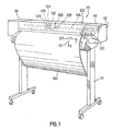
- a printer 110 includes a housing 112 mounted on a stand 114.
- the housing has left and right drive mechanism enclosures 116 and 118.
- a control panel 120 is mounted on the right enclosure 118.
- a carriage assembly 100 illustrated in phantom under a cover 122, is adapted for reciprocal motion along a carriage bar 124, also shown in phantom.
- the carriage assembly 100 comprises four inkjet printheads 102, 104, 106, 108 that store ink of different colours, e.g. black, magenta, cyan and yellow ink respectively, and an optical sensor 105.
- the position of the carriage assembly 100 in a horizontal or carriage scan axis (Y) is determined by a carriage positioning mechanism with respect to an encoder strip. (not shown) .
- a print medium 130 such as paper is positioned along a vertical or media axis by a media axis mechanism (not shown).
- the media axis is called the X axis denoted as 101
- the scan axis is called the Y axis denoted as 103.
- an holddown system is globally referenced as 200.
- Such a holddown system 200 is located between the left and right drive mechanism enclosures 116 and 118.
- the width of the holddown system along the Y axis is at least equal to the maximum allowable width of the media. In this example it should allow the employment of medium having width up to 914 mm (36 inches).
- the inkjet printheads 102, 104, 106, 108, are held rigidly in the movable carriage 100 so that the printhead nozzles are above the surface of a portion of the medium 130 which lays substantially flat on a flat stationary support platen 400 of said holddown system 200.
- the flat platen 400 is shown in more details, and is located in a front position of the printer 110 and co-operate with a main driving roller 300, in the following identified also as the main roller, located in a rear position, and a plurality of pinch wheels 310, in this example 12 pinch wheels 310 are employed, which are controlled to periodically index or convey the medium across the surface of the platen 400.
- the force between each pinch wheels 310 and the main roller 300 is comprised between 3.33 N and 5 N, preferably 4.15 N.
- the main roller 300 is provided with a conventional surface having a plurality of circumferencial recesses 305 housing a corresponding plurality of protrusions 405 of the platen 400 extending towards the rear of the printer 110.
- This combination of features allows the medium 130 to reliably move from the main roller 300 to the platen 400 and vice versa.
- the gap between the roller 300 and the platen 400 may allow an edge of the medium to engage the back of the platen itself causing a paper jam.
- the printer 110 comprises, a vacuum source, in this case a fan not shown in the drawings, connected to the atmosphere through a plurality of holes, or apertures, 330, 350 and a vacuum channel 380; such vacuum source generates an air flow by sucking air from the atmosphere.
- a vacuum source in this case a fan not shown in the drawings, connected to the atmosphere through a plurality of holes, or apertures, 330, 350 and a vacuum channel 380; such vacuum source generates an air flow by sucking air from the atmosphere.
- the holes 330, 350 are distributed at a certain distance from the main roller.
- a plurality of first holes 330 lays in a line at a distance comprised between 10 mm and 30 mm, preferably 19 mm and a plurality of secondary holes 350, distributed preferably in line.
- the platen 400 is provided, according to this preferred example, with a plurality of substantially linear grooves having one end closer to and the opposed end further from the main roller 300. Such grooves are linked together to form a continuos slot 320, which crosses substantially the whole width of the platen 400, where such a continuous slot 320 is arranged to have a waved shape.
- the plurality of first holes, or slot holes 330, having a diameter comprises between 1.5 mm and 3.5 mm, preferably about 2.5 mm, are then distributed inside the waved slot 320, and in this embodiment are preferably located in the further part of the slot 320 with respect to the main roller 300.
- the vacuum can be only directly generated at a certain distance from the main roller 300 itself.
- the vacuum source when the vacuum source is activated and in presence of a medium on the platen 400, the vacuum can be expanded along all the slot extending the vacuum closer to the main roller 300.
- extending the vacuum means that the vacuum generated at one aperture, which is normally supplied to an area of the back of medium, is now supplied to an area of the back of the medium which is at least 10% bigger, preferably bigger than 500%.
- Size of the vacuum channel is a further parameter relevant to apply the proper vacuum to the back of the medium.
- the surface of squared section of the vacuum channel 380 is preferably bigger than the sum of the surface of all the apertures 330, 350 distributed within the platen 400. More preferably the surface of the squared section is as big as twice, or more, the sum of the surface of all the apertures 330, 340.
- the medium can still be indexed by the main roller 300 and the pinch rollers 310 even when we are printing close to the very end of the medium itself.
- high vacuum may crease the paper especially if the grooves of the slot 320 are wide and run parallel to the paper advance direction. Therefore is advisable to run the grooves at about 45° respect to the media axis X and optimise the slot width to minimise creases in the paper and to evenly distribute the vacuum.
- the groove if the groove is parallel to the advance direction, it may make the ink to migrate and create localised dark areas.
- the slot 320 has a depth deeper than 0.5 mm, preferably 1 mm, and a width comprises between 3 mm and 8 mm, preferably 5 mm.
- the continuous shape of the waved slot 320 helps the holddown system 200 to evenly distribute the vacuum along the print zone 450.
- an interrupted sequence of grooves may create areas, having a reduced vacuum, which cross the complete print zone 450, in the media axis direction X. This may force the ink applied in those areas to migrate and create localised dark or clear portions in the printout.
- each recess 360 is composed by two parts, a first one substantially squared and a second one substantially triangular, where the triangular part lays on a plane which deeper than the plane on which the squared part lays.
- each squared part is provided with a secondary hole 350, having a diameter comprises between 1.5 and 2.5 mm, preferably 2.0.
- Such sequence of secondary recesses 360 is combined with a sequence of overdrive wheels 340, forming a secondary roller 345, such that a group of 3 consecutive secondary recesses 360 is disposed between two consecutive wheels 340.
- Such a secondary roller is housed in the vacuum channel 380.
- this holddown system 200 comprises 12 overdrive wheels 340 equally separated along the scan axis (Y) to supply equal traction to each part of the medium.
- an overdrive wheel may mean a single wheel as well as a plurality of wheels in strict contact one to another, in order to build a wheel having a larger width.
- a secondary recess 360 is distanced by each adjacent element, both a further secondary recess 360 or a wheel 340, by a rib 370.
- the ribs are employed to reduce the risk of generating cockle wrinkles which may extend towards the print zone 450.
- two consecutive ribs 370 having a preferably height of 1 mm, are distanced one to another by a distance comprised between 15 mm and 25 mm, preferably about 20 mm if the two ribs 370 are separated by a secondary recess 360.
- the plurality of secondary holes 350 provides the vacuum channel 380 with further apertures for the air flow generated by the vacuum source.
- the particular shape of the recesses 360 helps to provide the air flow with a smooth transition, reducing the resulting noise.
- the vacuum generated in correspondence of the secondary holes 350 is extended, in order to apply a negative pressure to most of the medium 130 laying on the platen 400.
- the vacuum is extended particularly due to the presence of the overdrive wheels 340, and the ribs 370, which create a larger empty space between the medium 130 and the platen 400.
- this part of the holddown system helps the printer to reduce the cockle effect on the printout.
- a secondary roller 345 having the function of tensioning the paper during the printing operation, may help in controlling the occurrence of the cockle wrinkles in the printout.
- vacuum is furnished through the plurality of holes 350 and the gap between each overdrive wheel 340 and its surrounding portion of the platen 400.
- Vacuum is used to provide the force between medium and overdrive wheels 340; the design has been done in such a way that it can provide the required force to the overdrive wheel 340, preferably comprised between 0.6 N and 1 N, in this example 0.8 N per each wheel 340, without employing starwheels. Elimination of starwheels is an important issue since it helps to avoid a) the risk of damaging the printout with starwheel marks, b)the need to employ a mechanism or a structure to hold the starwheels themselves.
- the overdrive interference i.e. the distance between the surface of the platen 400 and the top of the a overdrive roller 340, is preferably maintained between 0.3 mm and 0.6 mm. Below 0.25 mm the traction falls quickly, towards zero traction at zero interference; if the interference is bigger than 0.65 mm, wrinkles created by the overdrive roller 340 can extend to the print zone 450.
- first reference sign 390 is traversing all the platen 400 from the right to the left side in the scan axis (Y) direction.
- first reference 390 is tangent to the slot 320, on the side closer to the main roller 300, and it could be in colour and/or in under-relief.
- This feature is used preferably in combination with a second reference 392, placed at one side end of the platen 400.
- the second reference is traversing the platen 400 in the media axis (X) direction, preferably starting from the first reference 390 to the end of the platen 400 further from the main roller 300.
- the user is provided with two references for placing correctly the edges of a cut media sheet, or a media roll, onto the platen 400 in order to load and feed the sheet into the printer 110.
- the first reference 390 is providing the user with a reference which can fully match an edge of the sheet, so simplifying the loading operation.
- a second reference is placed at one end of the platen 400, which is conventionally located at the right end of the printer, respect to the user placing the sheet.
- This combination of references enhances the easiness of the loading operation by the user, reducing the occurrence of inaccurate positioning of the medium, which may cause a paper jam, during the feeding or the printing phases.
- FIG 4 it is shown the main roller 300 and one of the pinch wheels 310 co-operating with one protrusion 405 of the platen 400 holding the medium 130.
- One of the overdrive wheels 340, tensioning the medium 130 in the print zone 450 is also shown. From Figure 4 it is better depicted that the vacuum channel 380 does not extend underneath the complete print zone 450, particularly the vacuum channel 380 is partially overlapped by a portion of the print zone 450 which is less than 90% of the complete print zone 450, preferably less than 50%, and more preferably about 30-35%.
- FIG. 5 a diagram showing nominal values supplied by the vacuum source, a fan, employed in this example. Those values have been measured running the fan at its full power of 24 V.
- the pressure unit on the Y axis is Pascal and air flow unit on the X axis is m 3 /min.
- Vacuum required to eliminate cockle wrinkles in a printer would be so high that is normally unfeasible; in fact, high vacuum may suck the ink right through the paper and at the same time generate a lot of noise.
- the vacuum level has been preferably set between 380 Pa and 440 Pa, which can be achieved by a small fan, producing acceptable level of noise, i.e. about 65 dBA.
- one characteristic of the fan considered particularly valuable has been the capability of providing a pressure of 300 Pa, when the air flow is at about 0.5 m 3 /min.
- a loading operation can be activated in a plurality of different ways, e.g. by a user selection of the operation from the front panel 120 of the printer 110, or more easily, as in this embodiment, by opening the cover 122.
- the vacuum source is powered on, at 16 V, in order to help the loading operation.
- a user In order to load a cut sheet of media into the printer, a user should place the top edge of the medium 130 in correspondence of the first reference 390, and the top portion of the right edge of the same medium 130 in correspondence of the second reference. During all this phase the vacuum on is helping the user in holding the medium 130 adherent to the platen 400, so that small adjustments in the position of the medium 130 can be done using only one hand. Accordingly, the risk of inadvertently damaging the medium 130 (e.g. due to fingerprints or to the fall of the medium 130 on the ground) are minimised.
- the feeding step may be activated in several ways. For instance, it is automatically activated after that sensors have sensed the proper positioning of the medium 130, or by user selection of the feeding operation from the front panel 118, or, as in this embodiment, by closing the cover 122.
- the overdrive wheels 340 start to move clockwise in order to advance the medium 130 towards the main roller 300, until the medium 130 itself is engaged between the main roller and the pinch wheels 310.
- the vacuum is maintained on to transmit the traction force from the overdrive wheels 340 to the medium 130.
- the main roller 300 in co-operation with the pinch rollers 310 and other conventional elements of the printer 110, starts to convey the medium, from the feeding guide, across the print zone defined onto the platen 400.
- the vacuum source is switched on, at a power according to the kind of media employed and/or to the kind of plot which will be printed.
- the vacuum is keeping the medium 130 substantially flat onto the print zone 450 defined on the platen 400 to allow a quality printing.
- the main roller is advancing the medium towards the overdrive wheels 340, to have the medium engaged by them.
- the medium should be tensioned in the media direction X to keep the cockle wrinkles under control.
- the printing may start even if the overdrive wheels 340 are not engaged yet with the medium.
- the advance of the medium in the print zone along the media axis direction X is performed by a pushing force provided by the main roller 300, moving counter-clockwise, and the pinch wheels 310, moving clockwise, and by a pulling force provided by the overdrive wheels 340, moving counter-clockwise too.
- Conventional printing steps allow the carriage assembly 100 to move the printheads 102, 104, 106, and 108, relative to the medium 130 along the scan axis Y, in order to apply ink to the medium 130, in one or more passes, and so reproducing the desired image.
- An outputting operation may be activated for instance a) automatically when a printing operation has been completed or aborted, or b ) manually by a user request.
- the printer verifies if the medium 130 to be outputted is a cut sheet or a roll. If the medium 130 is a roll a cutting step is performed. This means that the medium 130 is advanced in the cutting position and the vacuum source is powered on, at 22 V, to hold the medium substantially flat and minimise the movement of the same while a blade, not show, is traversing the medium 130 along the scan axis Y to cut the medium.
- the medium 130 is a cut sheet or after that the roll has been cut, the medium is advanced in the media axis direction X towards the front of the printer 110, i.e. further from the main roller 300.
- the advancement of the medium is performed by the counter-clockwise movement of the overdrive wheels 340, frictionally engaging a portion of the back of the medium 130, due to the negative pressure generated by the vacuum source applied to the medium 130. If a cut sheet of media 130 is still engaged with the main roller 300 and the pinch wheels 310, those elements are also co-operating to advance the medium.
- the overdrive wheels movement is stopped when most of the printout is advanced out of the printer, e.g. as shown in Figure 1.
- the vacuum source is kept on for the required time to dry the medium, so holding only an end region of the medium 130, preferably having length equal to the width of the medium 130 and about 50 mm in the media axis direction X.
- the vacuum is switched off to drop the medium 130, e.g. into a conventional collecting bin, not shown.
- the same holddown system e.g. having one platen and one vacuum source
- each of this operations may be performed also using independent holddown systems, i.e. independent holddown surfaces and/or independent vacuum source.
- independent holddown systems i.e. independent holddown surfaces and/or independent vacuum source.
- the skilled in the art is now aware that only some of those operations may be performed by means of a vacuum holddown system while the remaining ones may be performed employing conventional systems.
Landscapes
- Handling Of Sheets (AREA)
- Handling Of Cut Paper (AREA)
- Delivering By Means Of Belts And Rollers (AREA)
Description
- The present invention generally relates to hardcopy apparatus, such as copiers, printers, scanners, facsimiles, and more particularly to improved media holddown devices for such apparatus.
- Hardcopy apparatus and particularly in apparatus handling media of big size, such as large format printers, are supplied by moving the end of the printing media manually towards the input portion of the apparatus, the printing media usually being a roll of printing media or sheet of printing media or the like, the printing media being pushed manually until its front edge is gripped between the feed roller and the drive roller which advance the sheet or the roll.
- A problem which frequently arises in apparatus of this type is that, given the manual guidance of the printing media has to be carried out at a considerable distance from the front edge of the printing media, it is difficult to achieve good alignment of the printing media and , in many cases, this delays the operation of the printer when this operation has to be repeated, since the printer cannot tolerate appreciable deviation of the printing media from the theoretical position.
- As is clear, the need from a repetition of the said loading operation results in loss of time.
- Furthermore, a feeding operation of a printing media not properly positioned may result in a paper jam, with a consequent loss of paper, which may be very expansive depending on its size and quality, as well as in a further loss of time for removing the paper jam.
- Alternatively, an improved method of loading media into a printer is disclosed in the European patent application no. 97 500153.8 published as EP 900664 A. In this application the method of loading the printing media into the printer provides for the operation of the rollers for advancing the printing media to be activated manually by the operator himself at the moment when the said printed media is introduced into the printer and at the moment when the operator estimates that the sheet of printing media is correctly positioned , without deviation.
- However, also in this case manual loading and positioning of media appears to be cumbersome, in particular when cut sheet of media are employed. In fact it is still difficult to achieve good alignment of the printing media since few references are provided to the operator in order to estimate if the media is correctly positioned or not.
- Finally, both the solutions cause a sharp change of status of the media, i.e. from completely free to stably locked. This change may cause an unintentional modification of the position of the media, which may result in an incorrect feeding of the sheet into the printer.
- Conventionally, sheet holddown devices such as electrostatic or suction devices are employed only to reduce the effects of paper curl and cockle on dot placement during printing. In vacuum holddown devices, sheet flatness is maintained by providing suction between a support plate and the back surface of a sheet to be handled.
- Cockle effect is the reluctance of the paper to bend smoothly. Instead it bends locally in a sharp fashion, creating permanent wrinkles.
- Although conventional vacuum holddown devices are fairly effective in maintaining sheet flatness during printing, they have drawbacks. One drawback is the complexity of maintaining the same holddown force along the entire width of the medium while printing, i.e. in the direction of the printheads motion. This is due to the losses of air that the conventional devices allow, causing the medium to be subject to different forces, i.e. forcing the medium to rotate while it is advanced in the direction of the media motion.
- Another drawback is that on one hand the maximum holddown force on a sheet is limited because of the necessity to maintain low frictional loads on transport devices which index the sheets. In conventional inkjet printers, such limitations can cause pen-to-sheet spacing distances to vary from swath to swath. Consequently, the holddown pressure at a localised area being printed may be insufficient to flatten cockles and other paper irregularities. On the other hand the vacuum required to eliminate cockle wrinkles in a printout would be so high that is normally unfeasible; in fact, high vacuum may suck the ink right through the paper and at the same time generate a lot of noise.
- Applicant has then experimented that the employment of a vacuum holddown input unit may help media to be properly manually positioned by the operator.
- Japanese Patent Application no. 10 035 186A describes a drawing instruments where the medium is manually loaded into the instrument, with no vacuum aid. When the paper is first introduced by the user into the instrument a sensor detects it, but only after a specified time passes, a fan is switched on to actuate a vacuum force. Such time delay allows the operator to position the medium on a platen between 2 driving and press rollers (14, 12), which have been previously disengaged. Then, once that the paper is held on the platen by the vacuum force, the operator can adjust the position of the paper by fitting a mark drawn on the platen. After the positioning of the paper is completed, the operators operates a lever to engage the two rollers with the paper and the vacuum is switched off.
- The present invention seeks to provide an improved hardcopy apparatus and method of loading a printing medium in the hardcopy apparatus.
- According to an aspect of the present invention, there is provided a hardcopy apparatus comprising a main roller and a loading mechanism to load a medium into the hardcopy apparatus, said loading mechanism comprises a vacuum holddown input unit to hold media down onto a surface of said holddown unit and positioning means, to allow a manual positioning of a portion of the medium onto said surface of said input unit.
- This reduces the risk of any unintentional modifications of its positioning. In fact the medium always stays in a sort of partially bounded condition, i.e. it is stably hold, unless a significant force is applied in order to have it moved, since the vacuum is not switched off during the positioning operation. It should be noted that, direct contact of the holddown device with the printing surface is avoided to minimise signs and other adverse affects on print appearance.
- Preferably, said holddown unit comprises a vacuum source, connected to atmosphere through a plurality of first apertures formed into the surface, and a vacuum channel to generate a negative pressure capable of holding down media onto the surface, while loading a medium
- In a preferred embodiment, said surface further comprises a plurality of recesses, at least one of said plurality of first apertures is located in one of said plurality of recesses.
- However, the air flow between the surface and the back of the medium may generate noise in correspondence of the first apertures.
- Accordingly, in a preferred arrangement, at least one of said plurality of recesses comprises a first portion capable of uniformly distributing the vacuum on an area substantially bigger than the aperture itself, and a second portion so shaped to reduce air flow noise interference with media.
- This result is achieved since the shape of the recesses is designed for providing the air flow with a smooth transition, reducing the resulting noise.
- Typically, said holddown unit further comprises a plurality of second apertures formed into the surface to create an additional negative pressure capable to increase the stability of media onto the surface. Advantageously, said holddown unit further comprises means to extend the additional negative pressure to a position closer to the drive roller.
- This feature allows the media to be loaded in a position closer to the drive roller, reducing the distance to be covered during the feeding operation to engage an edge of the medium with the drive roller.
- Preferably, said means for extending the negative pressure comprise a plurality of grooves extending towards the drive roller and a number of said plurality of second apertures are located within said grooves and each aperture (330) of said plurality of second apertures being located within a groove.
- In a further preferred embodiment, said holddown unit further comprises feeding means, being the generated negative pressure capable to engage the back of the medium with said feeding means and transfer said medium to engage said drive roller.
- Accordingly, the apparatus may be kept free from any additional elements which may reduce the operator's access to the input surface, reducing the complexity of his manual activity.
- Additionally, said feeding means comprises one or more overdrive wheels disposed to form on the surface an alternating sequence of recesses and overdrive wheels in the direction perpendicular to the direction of motion of media.
- In a further preferred arrangement, the holddown unit further comprises a first reference for placing the medium in a correct position on the surface, said first reference crossing the surface in the direction perpendicular to the direction of motion of media and a second reference for placing the medium in the right position on the surface, said second reference crossing the surface in the direction of motion of media.
- Thanks to the input surface mainly free of obstacles the operator can be provided with a full visual control of a plurality of references, to help him in positioning the medium.
- Preferably, said first reference is tangent to the portion of the grooves closer to the main roller. In this way, one edge of medium can be positioned at the very limit of the area capable of applying vacuum to the back of the medium.
- More preferably, said medium is a cut sheet of media.
- Viewing another aspect of the present invention, there is also provided, a method of loading a medium into a hardcopy apparatus including a holddown unit provided with a vacuum source, a main driving roller and a secondary roller, which comprises the steps of: manually positioning the medium onto a surface of the holddown unit; by rotating the secondary roller, advancing the medium towards the main roller; and engaging the medium to the main roller.
- Preferably, the step of keeping the vacuum source activated during all the previous steps, in order to achieve the engagement of the secondary roller with the back of the medium.
- In a preferred embodiment, the hardcopy apparatus further comprises one or more wheels, while the step of advancing the medium comprises the step of moving the one or more wheels clockwise or counter-clockwise, depending on the advancing direction of the medium.
- The present invention will be described further, by way of example only, with reference to an embodiment thereof as illustrated in the accompanying drawings in which:
- Figure 1 is a perspective view of an inkjet printer incorporating the features of the present invention;
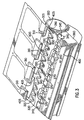
- Figure 2 is a more detailed diagram of a holddown system within the printer of Figure 1;
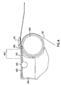
- Figure 3 depicts a portion of the holddown system of Figure 2;
- Figure 4 is a section of the main hardware components of the holddown system within the printer of Figure 1;
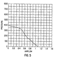
- Figure 5 depicts a test curve of nominal values of the pressure applied to a medium vs. air flow provided by a vacuum device, employed in the holddown system of the preceding figures, in the rated voltage of 24 V.
-
- Referring to Figure1, a
printer 110 includes ahousing 112 mounted on astand 114. The housing has left and rightdrive mechanism enclosures control panel 120 is mounted on theright enclosure 118. Acarriage assembly 100 illustrated in phantom under acover 122, is adapted for reciprocal motion along acarriage bar 124, also shown in phantom. Thecarriage assembly 100 comprises fourinkjet printheads carriage assembly 100 translates relative to the medium 130 along the X and Y axis, selected nozzles of theprintheads carriage assembly 100 in a horizontal or carriage scan axis (Y) is determined by a carriage positioning mechanism with respect to an encoder strip. (not shown) . Aprint medium 130 such as paper is positioned along a vertical or media axis by a media axis mechanism (not shown). As used herein, the media axis is called the X axis denoted as 101, and the scan axis is called the Y axis denoted as 103. - Referring now to Figure 2, an holddown system is globally referenced as 200. Such a
holddown system 200 is located between the left and rightdrive mechanism enclosures holddown system 200 will be made further with reference to Figure 3. Theinkjet printheads movable carriage 100 so that the printhead nozzles are above the surface of a portion of the medium 130 which lays substantially flat on a flatstationary support platen 400 of saidholddown system 200. - With reference to Figure 3, the
flat platen 400 is shown in more details, and is located in a front position of theprinter 110 and co-operate with amain driving roller 300, in the following identified also as the main roller, located in a rear position, and a plurality ofpinch wheels 310, in this example 12pinch wheels 310 are employed, which are controlled to periodically index or convey the medium across the surface of theplaten 400. The force between each pinchwheels 310 and themain roller 300 is comprised between 3.33 N and 5 N, preferably 4.15 N. - This pinch wheel distribution and force helps to drive the medium 130 straight with irrelevant lateral slippage, to share the medium 130 expansion on all its width. In fact has been observed that printers with low forces, e.g. about 1 N, allow media expansion accumulates in a particular place and this may cause a wrinkle to get so big to create a crash of the printhead.
- The
main roller 300 is provided with a conventional surface having a plurality ofcircumferencial recesses 305 housing a corresponding plurality ofprotrusions 405 of theplaten 400 extending towards the rear of theprinter 110. This combination of features allows the medium 130 to reliably move from themain roller 300 to theplaten 400 and vice versa. In fact the gap between theroller 300 and theplaten 400 may allow an edge of the medium to engage the back of the platen itself causing a paper jam. - The
printer 110 comprises, a vacuum source, in this case a fan not shown in the drawings, connected to the atmosphere through a plurality of holes, or apertures, 330, 350 and avacuum channel 380; such vacuum source generates an air flow by sucking air from the atmosphere. - Due to the pressure differential between atmosphere pressure on the surface of the medium 130 and the vacuum applied through the
vacuum channel 380 and theholes holes platen 400. - In order to reduce the losses of air from the
vacuum channel 380, theholes first holes 330 lays in a line at a distance comprised between 10 mm and 30 mm, preferably 19 mm and a plurality ofsecondary holes 350, distributed preferably in line. - Furthermore, the
platen 400 is provided, according to this preferred example, with a plurality of substantially linear grooves having one end closer to and the opposed end further from themain roller 300. Such grooves are linked together to form acontinuos slot 320, which crosses substantially the whole width of theplaten 400, where such acontinuous slot 320 is arranged to have a waved shape. - The plurality of first holes, or slot
holes 330, having a diameter comprises between 1.5 mm and 3.5 mm, preferably about 2.5 mm, are then distributed inside the wavedslot 320, and in this embodiment are preferably located in the further part of theslot 320 with respect to themain roller 300. - It is important to note that since the
main roller 300 is not included within thevacuum channel 380, the vacuum can be only directly generated at a certain distance from themain roller 300 itself. However, if theslot 320 is included in the unit, when the vacuum source is activated and in presence of a medium on theplaten 400, the vacuum can be expanded along all the slot extending the vacuum closer to themain roller 300. - In this application extending the vacuum means that the vacuum generated at one aperture, which is normally supplied to an area of the back of medium, is now supplied to an area of the back of the medium which is at least 10% bigger, preferably bigger than 500%.
- This helps in more uniformly apply the vacuum to the back of the medium, reducing the risk of having peak of vacuum that may crease the medium. Furthermore, thanks to the
slot 320 there is no need to conventionally include themain roller 300 into thevacuum channel 380 and this means that: a) the air losses are minimised, since in conventional systems, having the main roller included in the vacuum channel, most of the air is lost around the main roller itself; b) the air flow is forwarded towards themain roller 300, meaning that aprint zone 450 can be defined closer to themain roller 300; and c) the dimensions of the vacuum channel can be better controlled, giving more design freedom for designing the holddown system. - Size of the vacuum channel is a further parameter relevant to apply the proper vacuum to the back of the medium. Experiments run by the Applicant have shown that the surface of squared section of the
vacuum channel 380, as depicted in Figure 3, is preferably bigger than the sum of the surface of all theapertures platen 400. More preferably the surface of the squared section is as big as twice, or more, the sum of the surface of all theapertures - According to the above, it is possible to print closer to the edges of a cut medium. In fact the medium can still be indexed by the
main roller 300 and thepinch rollers 310 even when we are printing close to the very end of the medium itself. - Applicant's extended tests have revealed that a width too wide of the slot can reduce the capability of maintaining the medium substantially flat while printing, so affecting the printing quality. On the contrary, a width too narrow and/or an insufficient depth may affect the air flow direction, i.e. the vacuum force is not extended close enough to the
main roller 300. - Furthermore, high vacuum may crease the paper especially if the grooves of the
slot 320 are wide and run parallel to the paper advance direction. Therefore is advisable to run the grooves at about 45° respect to the media axis X and optimise the slot width to minimise creases in the paper and to evenly distribute the vacuum. In addition, if the groove is parallel to the advance direction, it may make the ink to migrate and create localised dark areas. - This means that it is not necessary that the plurality of grooves are linked together in order to form a continuous slot for achieving the above advantage.
- Accordingly, the
slot 320 has a depth deeper than 0.5 mm, preferably 1 mm, and a width comprises between 3 mm and 8 mm, preferably 5 mm. - However, the continuous shape of the waved
slot 320 helps theholddown system 200 to evenly distribute the vacuum along theprint zone 450. In fact, an interrupted sequence of grooves may create areas, having a reduced vacuum, which cross thecomplete print zone 450, in the media axis direction X. This may force the ink applied in those areas to migrate and create localised dark or clear portions in the printout. - Further from the waved
slot 320, along the media axis (X), theplaten 400 is provided with a plurality of secondary recesses 360, distributed in one line along the scan axis (Y). In this example each recess 360 is composed by two parts, a first one substantially squared and a second one substantially triangular, where the triangular part lays on a plane which deeper than the plane on which the squared part lays. - Furthermore, each squared part is provided with a
secondary hole 350, having a diameter comprises between 1.5 and 2.5 mm, preferably 2.0. Such sequence of secondary recesses 360 is combined with a sequence ofoverdrive wheels 340, forming asecondary roller 345, such that a group of 3 consecutive secondary recesses 360 is disposed between twoconsecutive wheels 340. Such a secondary roller is housed in thevacuum channel 380. - Thus, this
holddown system 200 comprises 12overdrive wheels 340 equally separated along the scan axis (Y) to supply equal traction to each part of the medium. - In this description an overdrive wheel may mean a single wheel as well as a plurality of wheels in strict contact one to another, in order to build a wheel having a larger width.
- A secondary recess 360 is distanced by each adjacent element, both a further secondary recess 360 or a
wheel 340, by arib 370. The ribs are employed to reduce the risk of generating cockle wrinkles which may extend towards theprint zone 450. - Accordingly, two
consecutive ribs 370, having a preferably height of 1 mm, are distanced one to another by a distance comprised between 15 mm and 25 mm, preferably about 20 mm if the tworibs 370 are separated by a secondary recess 360. - The plurality of
secondary holes 350 provides thevacuum channel 380 with further apertures for the air flow generated by the vacuum source. - Since the air flow between the top of the
platen 400 and the back of the medium 130 may generate noise in correspondence of thesecondary holes 350, the particular shape of the recesses 360 helps to provide the air flow with a smooth transition, reducing the resulting noise. - As for the slot holes 330, the vacuum generated in correspondence of the
secondary holes 350 is extended, in order to apply a negative pressure to most of the medium 130 laying on theplaten 400. The vacuum is extended particularly due to the presence of theoverdrive wheels 340, and theribs 370, which create a larger empty space between the medium 130 and theplaten 400. - Furthermore, the design of this part of the holddown system helps the printer to reduce the cockle effect on the printout.
- Tensioning the paper in the feeding direction intuitively does not help, because cockle wrinkles mainly extend in the feeding direction as well. Anyway, overdrive forces can reduce the height reached by the cockle wrinkles by as much as a half. In addition, it was noted how the paper works in compression, some very thin papers may even buckle and create loops between the
main roller 300 and the print zone. - This means that the presence of a
secondary roller 345, having the function of tensioning the paper during the printing operation, may help in controlling the occurrence of the cockle wrinkles in the printout. - However, it should be kept in mind that such a
secondary roller 345 provide theprinter 110 with more capabilities, which will be described further. - In this portion of the
platen 400, vacuum is furnished through the plurality ofholes 350 and the gap between eachoverdrive wheel 340 and its surrounding portion of theplaten 400. - Vacuum is used to provide the force between medium and
overdrive wheels 340; the design has been done in such a way that it can provide the required force to theoverdrive wheel 340, preferably comprised between 0.6 N and 1 N, in this example 0.8 N per eachwheel 340, without employing starwheels. Elimination of starwheels is an important issue since it helps to avoid a) the risk of damaging the printout with starwheel marks, b)the need to employ a mechanism or a structure to hold the starwheels themselves. - In addition, according to this example, in order to transmit the proper traction force to the medium, the overdrive interference, i.e. the distance between the surface of the
platen 400 and the top of the aoverdrive roller 340, is preferably maintained between 0.3 mm and 0.6 mm. Below 0.25 mm the traction falls quickly, towards zero traction at zero interference; if the interference is bigger than 0.65 mm, wrinkles created by theoverdrive roller 340 can extend to theprint zone 450. - In Figures 2 and 3 it is also shown a
first reference sign 390, according to this example, in the form of a phantom line, but any kind of suitable reference can be employed, e.g. a continuous or dotted line. Thisfirst reference 390 is traversing all theplaten 400 from the right to the left side in the scan axis (Y) direction. Preferably thefirst reference 390 is tangent to theslot 320, on the side closer to themain roller 300, and it could be in colour and/or in under-relief. This feature is used preferably in combination with asecond reference 392, placed at one side end of theplaten 400. The second reference is traversing theplaten 400 in the media axis (X) direction, preferably starting from thefirst reference 390 to the end of theplaten 400 further from themain roller 300. - Accordingly, the user is provided with two references for placing correctly the edges of a cut media sheet, or a media roll, onto the
platen 400 in order to load and feed the sheet into theprinter 110. Particularly, thefirst reference 390 is providing the user with a reference which can fully match an edge of the sheet, so simplifying the loading operation. - In this embodiment a second reference is placed at one end of the
platen 400, which is conventionally located at the right end of the printer, respect to the user placing the sheet. - This combination of references enhances the easiness of the loading operation by the user, reducing the occurrence of inaccurate positioning of the medium, which may cause a paper jam, during the feeding or the printing phases.
- Referring now to Figure 4, it is shown the
main roller 300 and one of thepinch wheels 310 co-operating with oneprotrusion 405 of theplaten 400 holding the medium 130. One of theoverdrive wheels 340, tensioning the medium 130 in theprint zone 450, is also shown. From Figure 4 it is better depicted that thevacuum channel 380 does not extend underneath thecomplete print zone 450, particularly thevacuum channel 380 is partially overlapped by a portion of theprint zone 450 which is less than 90% of thecomplete print zone 450, preferably less than 50%, and more preferably about 30-35%. - Referring now to Figure 5, a diagram showing nominal values supplied by the vacuum source, a fan, employed in this example. Those values have been measured running the fan at its full power of 24 V. The pressure unit on the Y axis is Pascal and air flow unit on the X axis is m3/min.
- Vacuum required to eliminate cockle wrinkles in a printer would be so high that is normally unfeasible; in fact, high vacuum may suck the ink right through the paper and at the same time generate a lot of noise.
- The vacuum level has been preferably set between 380 Pa and 440 Pa, which can be achieved by a small fan, producing acceptable level of noise, i.e. about 65 dBA.
- Several test run by the Applicant have verified that this level is enough for rigid roll paper, like high glossy photo roll, in order to flatten the curling during printing. In addition, it has been verified with many print modes that this level of vacuum is unlikely to suck the ink through the paper.
- Five operational levels of vacuum have been defined for the following activities:
Normal CAD printing 21 V Thick paper and high density prints 24 V Loading and cutting media 22 V Holddown during cut sheet loading 16 V Managing thin Japanese rice paper, always 14 V - According to Figure 5 and to the tests run by the Applicant, one characteristic of the fan considered particularly valuable has been the capability of providing a pressure of 300 Pa, when the air flow is at about 0.5 m3/min.
- Now reference is made to Figures 1, 2, 3 and 4 in order to describe how a medium can be loaded into, printed with and outputted from the
printer 110. - A loading operation can be activated in a plurality of different ways, e.g. by a user selection of the operation from the
front panel 120 of theprinter 110, or more easily, as in this embodiment, by opening thecover 122. - Once that the loading operation is activated the vacuum source is powered on, at 16 V, in order to help the loading operation.
- In the following an example on how to load a cut sheet of media will be described. However a skilled in the art may appreciate that, similarly, a roll of media may also be load.
- In order to load a cut sheet of media into the printer, a user should place the top edge of the medium 130 in correspondence of the
first reference 390, and the top portion of the right edge of thesame medium 130 in correspondence of the second reference. During all this phase the vacuum on is helping the user in holding the medium 130 adherent to theplaten 400, so that small adjustments in the position of the medium 130 can be done using only one hand. Accordingly, the risk of inadvertently damaging the medium 130 (e.g. due to fingerprints or to the fall of the medium 130 on the ground) are minimised. - Once that the loading step has been completed, the medium 130 is fed into the printer for the printing phase. The feeding step may be activated in several ways. For instance, it is automatically activated after that sensors have sensed the proper positioning of the medium 130, or by user selection of the feeding operation from the
front panel 118, or, as in this embodiment, by closing thecover 122. - Once that feeding step is activated, the
overdrive wheels 340 start to move clockwise in order to advance the medium 130 towards themain roller 300, until the medium 130 itself is engaged between the main roller and thepinch wheels 310. The vacuum is maintained on to transmit the traction force from theoverdrive wheels 340 to the medium 130. - As soon as main roller is fed with the medium 130, conventional steps are carried on in order to remove the medium 130 from the
platen 400 and to convey the medium 130, into a feeding guide for a subsequent printing phase. Finally, the vacuum source is switched off. - When a printing operation is activated, the
main roller 300 in co-operation with thepinch rollers 310 and other conventional elements of theprinter 110, starts to convey the medium, from the feeding guide, across the print zone defined onto theplaten 400. Contemporarily, the vacuum source is switched on, at a power according to the kind of media employed and/or to the kind of plot which will be printed. Thus, the vacuum is keeping the medium 130 substantially flat onto theprint zone 450 defined on theplaten 400 to allow a quality printing. Preferably, before starting printing, the main roller is advancing the medium towards theoverdrive wheels 340, to have the medium engaged by them. In fact, as already explained, the medium should be tensioned in the media direction X to keep the cockle wrinkles under control. Alternatively, the printing may start even if theoverdrive wheels 340 are not engaged yet with the medium. - Once that the medium 130 is also engaged by the overdrive wheels the advance of the medium in the print zone along the media axis direction X is performed by a pushing force provided by the
main roller 300, moving counter-clockwise, and thepinch wheels 310, moving clockwise, and by a pulling force provided by theoverdrive wheels 340, moving counter-clockwise too. - Conventional printing steps allow the
carriage assembly 100 to move theprintheads - An outputting operation may be activated for instance a) automatically when a printing operation has been completed or aborted, or b ) manually by a user request.
- When the operation is activated the printer verifies if the medium 130 to be outputted is a cut sheet or a roll. If the medium 130 is a roll a cutting step is performed. This means that the medium 130 is advanced in the cutting position and the vacuum source is powered on, at 22 V, to hold the medium substantially flat and minimise the movement of the same while a blade, not show, is traversing the medium 130 along the scan axis Y to cut the medium.
- If the medium 130 is a cut sheet or after that the roll has been cut, the medium is advanced in the media axis direction X towards the front of the
printer 110, i.e. further from themain roller 300. - The advancement of the medium is performed by the counter-clockwise movement of the
overdrive wheels 340, frictionally engaging a portion of the back of the medium 130, due to the negative pressure generated by the vacuum source applied to the medium 130. If a cut sheet ofmedia 130 is still engaged with themain roller 300 and thepinch wheels 310, those elements are also co-operating to advance the medium. - In case that the printout printed onto the medium 130 requires an additional dry time, the overdrive wheels movement is stopped when most of the printout is advanced out of the printer, e.g. as shown in Figure 1. The vacuum source is kept on for the required time to dry the medium, so holding only an end region of the medium 130, preferably having length equal to the width of the medium 130 and about 50 mm in the media axis direction X.
- Finally, the vacuum is switched off to drop the medium 130, e.g. into a conventional collecting bin, not shown. The skilled in the art may appreciate that, in accordance to this preferred embodiment, the same holddown system, e.g. having one platen and one vacuum source, may be capable of being employed to perform a plurality different operations, such as loading and feeding operation, printing operation and outputting operation. However, each of this operations may be performed also using independent holddown systems, i.e. independent holddown surfaces and/or independent vacuum source. Furthermore, the skilled in the art is now aware that only some of those operations may be performed by means of a vacuum holddown system while the remaining ones may be performed employing conventional systems.
Claims (20)
- A hardcopy apparatus comprising a main roller (300) and a loading mechanism to load a medium (130) into the hardcopy apparatus (110) comprising a vacuum holddown input unit (200) to hold media down onto a surface (400) of said holddown unit (200), and positioning means, to allow a manual positioning of at least a portion of the medium onto said surface of said holddown unit (200).
- The hardcopy apparatus as claimed in claim 1, wherein said holddown unit (200) is capable of holding stably the medium down onto said surface while allowing said manual positioning of at least a portion of said medium.
- The hardcopy apparatus as claimed in claims 1 or 2, wherein said holddown unit (200) comprises a vacuum source, connected to atmosphere through a plurality of first apertures (350) formed into the surface (400), and a vacuum channel (380) to generate a negative pressure capable of holding down media onto the surface (400), while loading a medium (130).
- The hardcopy apparatus as claimed in claim 3, wherein said surface (400) further comprises a plurality of recesses (360), at least one of said plurality of first apertures (350) is located in one of said plurality of recesses (360).
- The hardcopy apparatus as claimed in claim 4, wherein at least one of said plurality of recesses (360) comprises a first portion capable of uniformly distributing the vacuum on an area substantially bigger than the aperture (350) itself, and a second portion so shaped to reduce air flow noise interference with media.
- The hardcopy apparatus as claimed in any of claims 3 to 5, wherein said holddown unit (200) further comprises a plurality of second apertures (330) formed into the surface (400) to create an additional negative pressure capable to increase the stability of media onto the surface (400).
- The hardcopy apparatus as claimed in claim 6, wherein said holddown unit (200) further comprises means (320) to extend the additional negative pressure to a position closer to the drive roller (300).
- The hardcopy apparatus as claimed in claim 7, wherein said means (320) for extending the negative pressure comprise a plurality of grooves extending towards the drive roller (300) and a number of said plurality of second apertures (330) are located within said grooves.
- The hardcopy apparatus as claimed in claim 8, wherein each aperture (330) of said plurality of second apertures being located within a groove.
- The hardcopy apparatus as claimed in any of the preceding claims, wherein said holddown unit (200) further comprises feeding means, being the generated negative pressure capable to engage the back of the medium (130) with said feeding means and transfer said medium (130) to engage said drive roller (300).
- The hardcopy apparatus as claimed in claim 10, wherein said feeding means comprises one or more overdrive wheels (340) disposed to form on the surface (400) an alternating sequence of recesses (360) and overdrive wheels (340) in the direction perpendicular to the direction of motion of media (Y).
- The hardcopy apparatus as claimed in claim 8 or 9, wherein the holddown unit (200) further comprises a first reference (390) for placing the medium in a correct position on the surface (400), said first reference crossing the surface (400) in the direction perpendicular to the direction of motion of media (Y).
- The hardcopy apparatus as claimed in claim 12, wherein the holddown unit (200) further comprises a second reference (392) for placing the medium in the right position on the surface (400), said second reference crossing the surface (400) in the direction of motion of media (X).
- The hardcopy apparatus as claimed in claim 12 or 13, wherein said first reference (390) is tangent to the portion of the grooves closer to the main roller (300).
- The hardcopy apparatus as claimed in any of the preceding claims, wherein said medium (130) is a cut sheet of media.
- the hardcopy apparatus as claimed in any of the preceding claims, wherein said loading mechanism is also an outputting mechanism to move the medium (130) out of said apparatus.
- A method of loading a medium (130) into a hardcopy apparatus (110) including a holddown unit provided with a vacuum source, a main driving roller (300) and a secondary roller (345), comprising the following steps:manually positioning at least a portion of said medium (130) onto a surface (400) of the holddown unit (200);by rotating the secondary roller (345), advancing the medium (130) towards the main roller (300); andengaging the medium (130) to the main roller (300).
- The method as claimed in claim 17, further comprising the step of: stably holding said at least a portion of said medium onto said surface (400) while allowing to manually positioning said at least a portion of said medium onto said surface (400).
- The method as claimed in claims 17 or 18, further comprising the step of keeping the vacuum source activated during all the methods steps of claim 17, in order to achieve the engagement of the secondary roller (345) with the back of the medium (130).
- The method as claimed in claim 19, wherein the hardcopy apparatus (110) further comprises one or more wheels (340) and the step of advancing the medium (130) comprises the step of moving the one or more wheels (340) clockwise or counter-clockwise, depending on the advancing direction of the medium (130).
Priority Applications (5)
| Application Number | Priority Date | Filing Date | Title |
|---|---|---|---|
| DE69829665T DE69829665T2 (en) | 1998-10-30 | 1998-10-30 | Paper-picture device and data carrier insertion method |
| EP98120707A EP0997307B1 (en) | 1998-10-30 | 1998-10-30 | Hardcopy apparatus and method for loading media |
| ES98120707T ES2236859T3 (en) | 1998-10-30 | 1998-10-30 | COPYING AND METHOD APPARATUS FOR LOADING PRINT SUPPORTS. |
| US09/428,758 US6386536B1 (en) | 1998-10-30 | 1999-10-28 | Hardcopy apparatus and method for loading media |
| JP11308115A JP2000135824A (en) | 1998-10-30 | 1999-10-29 | Hard copy apparatus and fixing method of medium therefor |
Applications Claiming Priority (1)
| Application Number | Priority Date | Filing Date | Title |
|---|---|---|---|
| EP98120707A EP0997307B1 (en) | 1998-10-30 | 1998-10-30 | Hardcopy apparatus and method for loading media |
Publications (2)
| Publication Number | Publication Date |
|---|---|
| EP0997307A1 EP0997307A1 (en) | 2000-05-03 |
| EP0997307B1 true EP0997307B1 (en) | 2005-04-06 |
Family
ID=8232905
Family Applications (1)
| Application Number | Title | Priority Date | Filing Date |
|---|---|---|---|
| EP98120707A Expired - Lifetime EP0997307B1 (en) | 1998-10-30 | 1998-10-30 | Hardcopy apparatus and method for loading media |
Country Status (5)
| Country | Link |
|---|---|
| US (1) | US6386536B1 (en) |
| EP (1) | EP0997307B1 (en) |
| JP (1) | JP2000135824A (en) |
| DE (1) | DE69829665T2 (en) |
| ES (1) | ES2236859T3 (en) |
Families Citing this family (8)
| Publication number | Priority date | Publication date | Assignee | Title |
|---|---|---|---|---|
| US6752553B2 (en) * | 2000-12-28 | 2004-06-22 | Seiko Epson Corporation | Recording apparatus |
| US6615150B1 (en) * | 2001-02-15 | 2003-09-02 | Eastman Kodak Company | Method for detecting errors in loading a lenticular material on a printer |
| US6695503B1 (en) | 2002-10-02 | 2004-02-24 | Lexmark International, Inc. | Print media feed system for an imaging apparatus |
| US20090085947A1 (en) * | 2007-09-28 | 2009-04-02 | Kabushiki Kaisha Toshiba | Inkjet recording device, image forming method and recording device |
| USD700608S1 (en) * | 2011-05-19 | 2014-03-04 | Roth + Weber Gmbh | Wide format scanner or printer |
| US8905537B2 (en) | 2012-05-30 | 2014-12-09 | Hewlett-Packard Development Company, L.P. | Media handling device including a carrier structure for a set of starwheels |
| USD894271S1 (en) * | 2018-07-10 | 2020-08-25 | Seiko Epson Corporation | Printer |
| JP6568329B1 (en) * | 2019-01-25 | 2019-08-28 | ローランドディー.ジー.株式会社 | Inkjet printer |
Citations (2)
| Publication number | Priority date | Publication date | Assignee | Title |
|---|---|---|---|---|
| US4792249A (en) * | 1985-09-20 | 1988-12-20 | Creative Associates Limited Partnership | Vacuum paper transport system for printer |
| JPH1035186A (en) * | 1996-07-19 | 1998-02-10 | Mutoh Ind Ltd | Automatic drafting machine |
Family Cites Families (11)
| Publication number | Priority date | Publication date | Assignee | Title |
|---|---|---|---|---|
| CH658316A5 (en) * | 1981-08-26 | 1986-10-31 | Contraves Gmbh | DRUM BODY WITH SURFACE STRUCTURE FOR THE DRUM OF A RECORDING DEVICE. |
| DE3331662A1 (en) * | 1983-09-02 | 1985-03-28 | M.A.N.- Roland Druckmaschinen AG, 6050 Offenbach | METHOD AND DEVICE FOR FITTING A CUSTOM SHEET INTO A PRINTING MACHINE |
| US4998715A (en) * | 1988-11-18 | 1991-03-12 | Am International, Inc. | Copy sheet holddown system |
| GB8901055D0 (en) * | 1989-01-18 | 1989-03-15 | Simon Container Mach Ltd | Apparatus for feeding boards or sheets from a stack |
| JPH02307797A (en) * | 1989-05-24 | 1990-12-20 | Hitachi Ltd | Xy plotter |
| JPH0329352U (en) * | 1989-07-19 | 1991-03-22 | ||
| US5414491A (en) * | 1994-02-14 | 1995-05-09 | Eastman Kodak Company | Vacuum holder for sheet materials |
| US5717446A (en) * | 1994-12-12 | 1998-02-10 | Xerox Corporation | Liquid ink printer including a vacuum transport system and method of purging ink in the printer |
| US5838354A (en) * | 1995-05-31 | 1998-11-17 | Olympus Optical Co., Ltd. | Image forming apparatus |
| DE69724247T2 (en) | 1997-09-02 | 2004-06-09 | Hewlett-Packard Co. (N.D.Ges.D.Staates Delaware), Palo Alto | Method of inserting recording media in a printer, printer using this method, and printhead and deflector combination for using this method |
| US6179285B1 (en) * | 1999-01-19 | 2001-01-30 | Xerox Corporation | Media transport assembly incorporating vacuum grooves to flatten sheet |
-
1998
- 1998-10-30 EP EP98120707A patent/EP0997307B1/en not_active Expired - Lifetime
- 1998-10-30 DE DE69829665T patent/DE69829665T2/en not_active Expired - Lifetime
- 1998-10-30 ES ES98120707T patent/ES2236859T3/en not_active Expired - Lifetime
-
1999
- 1999-10-28 US US09/428,758 patent/US6386536B1/en not_active Expired - Fee Related
- 1999-10-29 JP JP11308115A patent/JP2000135824A/en active Pending
Patent Citations (3)
| Publication number | Priority date | Publication date | Assignee | Title |
|---|---|---|---|---|
| US4792249A (en) * | 1985-09-20 | 1988-12-20 | Creative Associates Limited Partnership | Vacuum paper transport system for printer |
| JPH1035186A (en) * | 1996-07-19 | 1998-02-10 | Mutoh Ind Ltd | Automatic drafting machine |
| US6038776A (en) * | 1996-07-19 | 2000-03-21 | Mutoh Industries Ltd. | Automatic drafting machine |
Also Published As
| Publication number | Publication date |
|---|---|
| EP0997307A1 (en) | 2000-05-03 |
| DE69829665T2 (en) | 2006-03-09 |
| US6386536B1 (en) | 2002-05-14 |
| DE69829665D1 (en) | 2005-05-12 |
| ES2236859T3 (en) | 2005-07-16 |
| JP2000135824A (en) | 2000-05-16 |
Similar Documents
| Publication | Publication Date | Title |
|---|---|---|
| EP0997306B1 (en) | Hardcopy apparatus and method for outputting media | |
| EP0997302B1 (en) | Hardcopy apparatus and method for holding down media | |
| EP2292537B1 (en) | Printing medium feeding cassette and image forming apparatus inlcuding the same | |
| US7744210B2 (en) | Moving floor media transport for digital printers | |
| US6786664B2 (en) | Active vacuum roller and method for advancing media | |
| US6682190B2 (en) | Controlling media curl in print-zone | |
| EP0230548A2 (en) | Paper tray for a printing device | |
| EP0997307B1 (en) | Hardcopy apparatus and method for loading media | |
| US6367999B1 (en) | Hardcopy apparatus and method for providing uniform pressure to hold down media | |
| EP0997308B1 (en) | Hardcopy apparatus and method for providing uniform pressure to hold down media | |
| EP1022147B1 (en) | A media transport system | |
| EP1721750A1 (en) | Media holding assistance for a step-wise media transport system in a digital printer | |
| EP3251989A1 (en) | Web winding with friction-based tensioning | |
| WO2003070473A1 (en) | Printer, method for determining top edge of object to be printed, method for determining bottom edge of object to be printed, computer program, and computer system | |
| JP2001268310A (en) | Image forming apparatus and method for cutting roll-shaped recording medium | |
| US8561988B1 (en) | Media hold-down for printing system | |
| US6565081B1 (en) | Media outputting device and method for outputting media | |
| US20190308426A1 (en) | Feeding a print medium and printer | |
| JP2001071480A (en) | Printer device | |
| JPH02286546A (en) | Paper supply/discharge tray | |
| EP0453548B1 (en) | Improved compact printer having sheet and tractor media selections | |
| US12064955B2 (en) | Medium supporting mechanism and printing apparatus | |
| EP2580063B1 (en) | Printer assembly | |
| JPH0711993Y2 (en) | Paper transport device for printer | |
| JP2006159414A (en) | Roll paper printer |
Legal Events
| Date | Code | Title | Description |
|---|---|---|---|
| PUAI | Public reference made under article 153(3) epc to a published international application that has entered the european phase |
Free format text: ORIGINAL CODE: 0009012 |
|
| AK | Designated contracting states |
Kind code of ref document: A1 Designated state(s): DE ES FR GB NL |
|
| AX | Request for extension of the european patent |
Free format text: AL;LT;LV;MK;RO;SI |
|
| 17P | Request for examination filed |
Effective date: 20001030 |
|
| AKX | Designation fees paid |
Free format text: DE ES FR GB NL |
|
| RAP1 | Party data changed (applicant data changed or rights of an application transferred) |
Owner name: HEWLETT-PACKARD COMPANY, A DELAWARE CORPORATION |
|
| 17Q | First examination report despatched |
Effective date: 20020625 |
|
| GRAP | Despatch of communication of intention to grant a patent |
Free format text: ORIGINAL CODE: EPIDOSNIGR1 |
|
| GRAS | Grant fee paid |
Free format text: ORIGINAL CODE: EPIDOSNIGR3 |
|
| GRAA | (expected) grant |
Free format text: ORIGINAL CODE: 0009210 |
|
| AK | Designated contracting states |
Kind code of ref document: B1 Designated state(s): DE ES FR GB NL |
|
| REG | Reference to a national code |
Ref country code: GB Ref legal event code: FG4D |
|
| REF | Corresponds to: |
Ref document number: 69829665 Country of ref document: DE Date of ref document: 20050512 Kind code of ref document: P |
|
| REG | Reference to a national code |
Ref country code: ES Ref legal event code: FG2A Ref document number: 2236859 Country of ref document: ES Kind code of ref document: T3 |
|
| PLBE | No opposition filed within time limit |
Free format text: ORIGINAL CODE: 0009261 |
|
| STAA | Information on the status of an ep patent application or granted ep patent |
Free format text: STATUS: NO OPPOSITION FILED WITHIN TIME LIMIT |
|
| ET | Fr: translation filed | ||
| 26N | No opposition filed |
Effective date: 20060110 |
|
| PGFP | Annual fee paid to national office [announced via postgrant information from national office to epo] |
Ref country code: NL Payment date: 20071024 Year of fee payment: 10 Ref country code: ES Payment date: 20071026 Year of fee payment: 10 |
|
| PGFP | Annual fee paid to national office [announced via postgrant information from national office to epo] |
Ref country code: FR Payment date: 20070207 Year of fee payment: 9 |
|
| REG | Reference to a national code |
Ref country code: FR Ref legal event code: ST Effective date: 20080630 |
|
| PG25 | Lapsed in a contracting state [announced via postgrant information from national office to epo] |
Ref country code: FR Free format text: LAPSE BECAUSE OF NON-PAYMENT OF DUE FEES Effective date: 20071031 |
|
| NLV4 | Nl: lapsed or anulled due to non-payment of the annual fee |
Effective date: 20090501 |
|
| PG25 | Lapsed in a contracting state [announced via postgrant information from national office to epo] |
Ref country code: NL Free format text: LAPSE BECAUSE OF NON-PAYMENT OF DUE FEES Effective date: 20090501 |
|
| REG | Reference to a national code |
Ref country code: ES Ref legal event code: FD2A Effective date: 20081031 |
|
| PG25 | Lapsed in a contracting state [announced via postgrant information from national office to epo] |
Ref country code: ES Free format text: LAPSE BECAUSE OF NON-PAYMENT OF DUE FEES Effective date: 20081031 |
|
| REG | Reference to a national code |
Ref country code: GB Ref legal event code: 732E Free format text: REGISTERED BETWEEN 20120329 AND 20120404 |
|
| PGFP | Annual fee paid to national office [announced via postgrant information from national office to epo] |
Ref country code: DE Payment date: 20121029 Year of fee payment: 15 |
|
| PGFP | Annual fee paid to national office [announced via postgrant information from national office to epo] |
Ref country code: GB Payment date: 20121025 Year of fee payment: 15 |
|
| GBPC | Gb: european patent ceased through non-payment of renewal fee |
Effective date: 20131030 |
|
| REG | Reference to a national code |
Ref country code: DE Ref legal event code: R119 Ref document number: 69829665 Country of ref document: DE Effective date: 20140501 |
|
| PG25 | Lapsed in a contracting state [announced via postgrant information from national office to epo] |
Ref country code: GB Free format text: LAPSE BECAUSE OF NON-PAYMENT OF DUE FEES Effective date: 20131030 |
|
| PG25 | Lapsed in a contracting state [announced via postgrant information from national office to epo] |
Ref country code: DE Free format text: LAPSE BECAUSE OF NON-PAYMENT OF DUE FEES Effective date: 20140501 |