EP0996847B1 - Wärmetauscher und/oder flüssigkeitsmischvorrichtung - Google Patents
Wärmetauscher und/oder flüssigkeitsmischvorrichtung Download PDFInfo
- Publication number
- EP0996847B1 EP0996847B1 EP98924469A EP98924469A EP0996847B1 EP 0996847 B1 EP0996847 B1 EP 0996847B1 EP 98924469 A EP98924469 A EP 98924469A EP 98924469 A EP98924469 A EP 98924469A EP 0996847 B1 EP0996847 B1 EP 0996847B1
- Authority
- EP
- European Patent Office
- Prior art keywords
- plates
- plate
- heat exchanger
- adjacent
- perforations
- Prior art date
- Legal status (The legal status is an assumption and is not a legal conclusion. Google has not performed a legal analysis and makes no representation as to the accuracy of the status listed.)
- Expired - Lifetime
Links
Images


Classifications
-
- B—PERFORMING OPERATIONS; TRANSPORTING
- B01—PHYSICAL OR CHEMICAL PROCESSES OR APPARATUS IN GENERAL
- B01J—CHEMICAL OR PHYSICAL PROCESSES, e.g. CATALYSIS OR COLLOID CHEMISTRY; THEIR RELEVANT APPARATUS
- B01J19/00—Chemical, physical or physico-chemical processes in general; Their relevant apparatus
- B01J19/0006—Controlling or regulating processes
- B01J19/0013—Controlling the temperature of the process
-
- B—PERFORMING OPERATIONS; TRANSPORTING
- B01—PHYSICAL OR CHEMICAL PROCESSES OR APPARATUS IN GENERAL
- B01J—CHEMICAL OR PHYSICAL PROCESSES, e.g. CATALYSIS OR COLLOID CHEMISTRY; THEIR RELEVANT APPARATUS
- B01J19/00—Chemical, physical or physico-chemical processes in general; Their relevant apparatus
- B01J19/24—Stationary reactors without moving elements inside
- B01J19/248—Reactors comprising multiple separated flow channels
- B01J19/249—Plate-type reactors
-
- F—MECHANICAL ENGINEERING; LIGHTING; HEATING; WEAPONS; BLASTING
- F28—HEAT EXCHANGE IN GENERAL
- F28D—HEAT-EXCHANGE APPARATUS, NOT PROVIDED FOR IN ANOTHER SUBCLASS, IN WHICH THE HEAT-EXCHANGE MEDIA DO NOT COME INTO DIRECT CONTACT
- F28D9/00—Heat-exchange apparatus having stationary plate-like or laminated conduit assemblies for both heat-exchange media, the media being in contact with different sides of a conduit wall
- F28D9/0012—Heat-exchange apparatus having stationary plate-like or laminated conduit assemblies for both heat-exchange media, the media being in contact with different sides of a conduit wall the apparatus having an annular form
-
- F—MECHANICAL ENGINEERING; LIGHTING; HEATING; WEAPONS; BLASTING
- F28—HEAT EXCHANGE IN GENERAL
- F28D—HEAT-EXCHANGE APPARATUS, NOT PROVIDED FOR IN ANOTHER SUBCLASS, IN WHICH THE HEAT-EXCHANGE MEDIA DO NOT COME INTO DIRECT CONTACT
- F28D9/00—Heat-exchange apparatus having stationary plate-like or laminated conduit assemblies for both heat-exchange media, the media being in contact with different sides of a conduit wall
- F28D9/0062—Heat-exchange apparatus having stationary plate-like or laminated conduit assemblies for both heat-exchange media, the media being in contact with different sides of a conduit wall the conduits for one heat-exchange medium being formed by spaced plates with inserted elements
- F28D9/0068—Heat-exchange apparatus having stationary plate-like or laminated conduit assemblies for both heat-exchange media, the media being in contact with different sides of a conduit wall the conduits for one heat-exchange medium being formed by spaced plates with inserted elements with means for changing flow direction of one heat exchange medium, e.g. using deflecting zones
-
- F—MECHANICAL ENGINEERING; LIGHTING; HEATING; WEAPONS; BLASTING
- F28—HEAT EXCHANGE IN GENERAL
- F28D—HEAT-EXCHANGE APPARATUS, NOT PROVIDED FOR IN ANOTHER SUBCLASS, IN WHICH THE HEAT-EXCHANGE MEDIA DO NOT COME INTO DIRECT CONTACT
- F28D9/00—Heat-exchange apparatus having stationary plate-like or laminated conduit assemblies for both heat-exchange media, the media being in contact with different sides of a conduit wall
- F28D9/0062—Heat-exchange apparatus having stationary plate-like or laminated conduit assemblies for both heat-exchange media, the media being in contact with different sides of a conduit wall the conduits for one heat-exchange medium being formed by spaced plates with inserted elements
- F28D9/0075—Heat-exchange apparatus having stationary plate-like or laminated conduit assemblies for both heat-exchange media, the media being in contact with different sides of a conduit wall the conduits for one heat-exchange medium being formed by spaced plates with inserted elements the plates having openings therein for circulation of the heat-exchange medium from one conduit to another
-
- F—MECHANICAL ENGINEERING; LIGHTING; HEATING; WEAPONS; BLASTING
- F28—HEAT EXCHANGE IN GENERAL
- F28F—DETAILS OF HEAT-EXCHANGE AND HEAT-TRANSFER APPARATUS, OF GENERAL APPLICATION
- F28F3/00—Plate-like or laminated elements; Assemblies of plate-like or laminated elements
- F28F3/02—Elements or assemblies thereof with means for increasing heat-transfer area, e.g. with fins, with recesses, with corrugations
-
- F—MECHANICAL ENGINEERING; LIGHTING; HEATING; WEAPONS; BLASTING
- F28—HEAT EXCHANGE IN GENERAL
- F28F—DETAILS OF HEAT-EXCHANGE AND HEAT-TRANSFER APPARATUS, OF GENERAL APPLICATION
- F28F3/00—Plate-like or laminated elements; Assemblies of plate-like or laminated elements
- F28F3/08—Elements constructed for building-up into stacks, e.g. capable of being taken apart for cleaning
- F28F3/086—Elements constructed for building-up into stacks, e.g. capable of being taken apart for cleaning having one or more openings therein forming tubular heat-exchange passages
-
- B—PERFORMING OPERATIONS; TRANSPORTING
- B01—PHYSICAL OR CHEMICAL PROCESSES OR APPARATUS IN GENERAL
- B01J—CHEMICAL OR PHYSICAL PROCESSES, e.g. CATALYSIS OR COLLOID CHEMISTRY; THEIR RELEVANT APPARATUS
- B01J2219/00—Chemical, physical or physico-chemical processes in general; Their relevant apparatus
- B01J2219/00049—Controlling or regulating processes
- B01J2219/00051—Controlling the temperature
- B01J2219/00074—Controlling the temperature by indirect heating or cooling employing heat exchange fluids
-
- B—PERFORMING OPERATIONS; TRANSPORTING
- B01—PHYSICAL OR CHEMICAL PROCESSES OR APPARATUS IN GENERAL
- B01J—CHEMICAL OR PHYSICAL PROCESSES, e.g. CATALYSIS OR COLLOID CHEMISTRY; THEIR RELEVANT APPARATUS
- B01J2219/00—Chemical, physical or physico-chemical processes in general; Their relevant apparatus
- B01J2219/24—Stationary reactors without moving elements inside
- B01J2219/2401—Reactors comprising multiple separate flow channels
- B01J2219/245—Plate-type reactors
- B01J2219/2451—Geometry of the reactor
- B01J2219/2453—Plates arranged in parallel
-
- B—PERFORMING OPERATIONS; TRANSPORTING
- B01—PHYSICAL OR CHEMICAL PROCESSES OR APPARATUS IN GENERAL
- B01J—CHEMICAL OR PHYSICAL PROCESSES, e.g. CATALYSIS OR COLLOID CHEMISTRY; THEIR RELEVANT APPARATUS
- B01J2219/00—Chemical, physical or physico-chemical processes in general; Their relevant apparatus
- B01J2219/24—Stationary reactors without moving elements inside
- B01J2219/2401—Reactors comprising multiple separate flow channels
- B01J2219/245—Plate-type reactors
- B01J2219/2451—Geometry of the reactor
- B01J2219/2456—Geometry of the plates
- B01J2219/2459—Corrugated plates
-
- B—PERFORMING OPERATIONS; TRANSPORTING
- B01—PHYSICAL OR CHEMICAL PROCESSES OR APPARATUS IN GENERAL
- B01J—CHEMICAL OR PHYSICAL PROCESSES, e.g. CATALYSIS OR COLLOID CHEMISTRY; THEIR RELEVANT APPARATUS
- B01J2219/00—Chemical, physical or physico-chemical processes in general; Their relevant apparatus
- B01J2219/24—Stationary reactors without moving elements inside
- B01J2219/2401—Reactors comprising multiple separate flow channels
- B01J2219/245—Plate-type reactors
- B01J2219/2451—Geometry of the reactor
- B01J2219/2456—Geometry of the plates
- B01J2219/246—Perforated plates
-
- B—PERFORMING OPERATIONS; TRANSPORTING
- B01—PHYSICAL OR CHEMICAL PROCESSES OR APPARATUS IN GENERAL
- B01J—CHEMICAL OR PHYSICAL PROCESSES, e.g. CATALYSIS OR COLLOID CHEMISTRY; THEIR RELEVANT APPARATUS
- B01J2219/00—Chemical, physical or physico-chemical processes in general; Their relevant apparatus
- B01J2219/24—Stationary reactors without moving elements inside
- B01J2219/2401—Reactors comprising multiple separate flow channels
- B01J2219/245—Plate-type reactors
- B01J2219/2461—Heat exchange aspects
- B01J2219/2462—Heat exchange aspects the reactants being in indirect heat exchange with a non reacting heat exchange medium
-
- B—PERFORMING OPERATIONS; TRANSPORTING
- B01—PHYSICAL OR CHEMICAL PROCESSES OR APPARATUS IN GENERAL
- B01J—CHEMICAL OR PHYSICAL PROCESSES, e.g. CATALYSIS OR COLLOID CHEMISTRY; THEIR RELEVANT APPARATUS
- B01J2219/00—Chemical, physical or physico-chemical processes in general; Their relevant apparatus
- B01J2219/24—Stationary reactors without moving elements inside
- B01J2219/2401—Reactors comprising multiple separate flow channels
- B01J2219/245—Plate-type reactors
- B01J2219/2461—Heat exchange aspects
- B01J2219/2465—Two reactions in indirect heat exchange with each other
-
- B—PERFORMING OPERATIONS; TRANSPORTING
- B01—PHYSICAL OR CHEMICAL PROCESSES OR APPARATUS IN GENERAL
- B01J—CHEMICAL OR PHYSICAL PROCESSES, e.g. CATALYSIS OR COLLOID CHEMISTRY; THEIR RELEVANT APPARATUS
- B01J2219/00—Chemical, physical or physico-chemical processes in general; Their relevant apparatus
- B01J2219/24—Stationary reactors without moving elements inside
- B01J2219/2401—Reactors comprising multiple separate flow channels
- B01J2219/245—Plate-type reactors
- B01J2219/2469—Feeding means
- B01J2219/247—Feeding means for the reactants
-
- B—PERFORMING OPERATIONS; TRANSPORTING
- B01—PHYSICAL OR CHEMICAL PROCESSES OR APPARATUS IN GENERAL
- B01J—CHEMICAL OR PHYSICAL PROCESSES, e.g. CATALYSIS OR COLLOID CHEMISTRY; THEIR RELEVANT APPARATUS
- B01J2219/00—Chemical, physical or physico-chemical processes in general; Their relevant apparatus
- B01J2219/24—Stationary reactors without moving elements inside
- B01J2219/2401—Reactors comprising multiple separate flow channels
- B01J2219/245—Plate-type reactors
- B01J2219/2474—Mixing means, e.g. fins or baffles attached to the plates
-
- B—PERFORMING OPERATIONS; TRANSPORTING
- B01—PHYSICAL OR CHEMICAL PROCESSES OR APPARATUS IN GENERAL
- B01J—CHEMICAL OR PHYSICAL PROCESSES, e.g. CATALYSIS OR COLLOID CHEMISTRY; THEIR RELEVANT APPARATUS
- B01J2219/00—Chemical, physical or physico-chemical processes in general; Their relevant apparatus
- B01J2219/24—Stationary reactors without moving elements inside
- B01J2219/2401—Reactors comprising multiple separate flow channels
- B01J2219/245—Plate-type reactors
- B01J2219/2476—Construction materials
- B01J2219/2483—Construction materials of the plates
- B01J2219/2485—Metals or alloys
-
- B—PERFORMING OPERATIONS; TRANSPORTING
- B01—PHYSICAL OR CHEMICAL PROCESSES OR APPARATUS IN GENERAL
- B01J—CHEMICAL OR PHYSICAL PROCESSES, e.g. CATALYSIS OR COLLOID CHEMISTRY; THEIR RELEVANT APPARATUS
- B01J2219/00—Chemical, physical or physico-chemical processes in general; Their relevant apparatus
- B01J2219/24—Stationary reactors without moving elements inside
- B01J2219/2401—Reactors comprising multiple separate flow channels
- B01J2219/245—Plate-type reactors
- B01J2219/2491—Other constructional details
- B01J2219/2492—Assembling means
- B01J2219/2493—Means for assembling plates together, e.g. sealing means, screws, bolts
-
- B—PERFORMING OPERATIONS; TRANSPORTING
- B01—PHYSICAL OR CHEMICAL PROCESSES OR APPARATUS IN GENERAL
- B01J—CHEMICAL OR PHYSICAL PROCESSES, e.g. CATALYSIS OR COLLOID CHEMISTRY; THEIR RELEVANT APPARATUS
- B01J2219/00—Chemical, physical or physico-chemical processes in general; Their relevant apparatus
- B01J2219/24—Stationary reactors without moving elements inside
- B01J2219/2401—Reactors comprising multiple separate flow channels
- B01J2219/245—Plate-type reactors
- B01J2219/2491—Other constructional details
- B01J2219/2492—Assembling means
- B01J2219/2496—Means for assembling modules together, e.g. casings, holders, fluidic connectors
-
- B—PERFORMING OPERATIONS; TRANSPORTING
- B01—PHYSICAL OR CHEMICAL PROCESSES OR APPARATUS IN GENERAL
- B01J—CHEMICAL OR PHYSICAL PROCESSES, e.g. CATALYSIS OR COLLOID CHEMISTRY; THEIR RELEVANT APPARATUS
- B01J2219/00—Chemical, physical or physico-chemical processes in general; Their relevant apparatus
- B01J2219/24—Stationary reactors without moving elements inside
- B01J2219/2401—Reactors comprising multiple separate flow channels
- B01J2219/245—Plate-type reactors
- B01J2219/2491—Other constructional details
- B01J2219/2497—Size aspects, i.e. concrete sizes are being mentioned in the classified document
-
- B—PERFORMING OPERATIONS; TRANSPORTING
- B01—PHYSICAL OR CHEMICAL PROCESSES OR APPARATUS IN GENERAL
- B01J—CHEMICAL OR PHYSICAL PROCESSES, e.g. CATALYSIS OR COLLOID CHEMISTRY; THEIR RELEVANT APPARATUS
- B01J2219/00—Chemical, physical or physico-chemical processes in general; Their relevant apparatus
- B01J2219/24—Stationary reactors without moving elements inside
- B01J2219/2401—Reactors comprising multiple separate flow channels
- B01J2219/245—Plate-type reactors
- B01J2219/2491—Other constructional details
- B01J2219/2498—Additional structures inserted in the channels, e.g. plates, catalyst holding meshes
-
- F—MECHANICAL ENGINEERING; LIGHTING; HEATING; WEAPONS; BLASTING
- F28—HEAT EXCHANGE IN GENERAL
- F28F—DETAILS OF HEAT-EXCHANGE AND HEAT-TRANSFER APPARATUS, OF GENERAL APPLICATION
- F28F2250/00—Arrangements for modifying the flow of the heat exchange media, e.g. flow guiding means; Particular flow patterns
- F28F2250/10—Particular pattern of flow of the heat exchange media
- F28F2250/102—Particular pattern of flow of the heat exchange media with change of flow direction
Definitions
- This invention relates to a compact heat exchanger and/or fluid mixing means which incorporates a series of plates having apertures which define a plurality of passages through which fluid may flow.
- Compact heat exchangers are characterised by their high "area density” which means that they have a high ratio of heat transfer surface to heat exchanger volume. Area density is typically greater than 300m 2 /m 3 . and may be more than 700m 2 /m 3 . Such heat exchangers are typically used to cool (or heat) process fluids.
- heat exchanger One well known but expensive to manufacture type of heat exchanger is the so-called tube and shell heat exchanger.
- tube and shell heat exchangers consist of an exterior tubular shell through which run a number of longitudinally-extending smaller diameter tubes carrying one or more fluids. Other fluids, with which heat is to be exchanged, typically pass transversely across the heat exchanger such that heat is exchanged through the tube walls.
- a large number of tubes may be needed and they each have to be individually and accurately fixed/secured into a header plate at each end of the shell. In each case holes need to be drilled in the header plates very accurately to locate the tubes.
- High quality tested tubing then needs to be assembled into the plates and brazed or welded or mechanically-expanded into position.
- the tubes are reduced in diameter to increase surfaces available for heat transfer and hence performance/compactness, the more difficult and expensive such configurations become to manufacture.
- a second known type of heat exchanger is the so-called primary plate/secondary plate type exchanger in which a stack of plates is assembled, the stack having primary plates which directly separate two different fluid streams and secondary plates between adjacent primary plates.
- the secondary plates act as fins which add to the strength of structure and may be provided with perforations to provide additional flow paths for the fluids.
- the plates are usually bonded together by brazing but this may have the disadvantage of affecting the physical properties of the plates in the brazed regions or may introduce into the system, by means of the braze material, a potentially less satisfactory structure in terms of strength and corrosion resistance. It has been proposed to bond the plates together by diffusion bonding but a satisfactory construction that can withstand the high pressures involved has not been achieved and the fins may buckle during the bonding process.
- a fluid distributing device which may be a heat exchanger, in which channels for fluid flow are formed by the aligning of perforated plates such that the openings in the plates overlap partially in one direction across the plates and the lateral boundaries of the openings form a seal, thereby defining a number of flow channels across the plates.
- the plates defining the channels are encased between unperforated plates.
- the invention may provide a means whereby the exothermic heat of reaction may be removed efficiently or, alternatively, it may be used to supply heat to an endothermic reaction.
- the products of the invention are also useful as fuel reformers and gas clean-up units associated with fuel cell technology.
- the present invention provides a heat exchanger or fluid mixing means comprising a bonded stack of plates, the stack comprising at least one group of main perforated plates, wherein at least two adjacent plates of the group of main perforated plates have their perforations aligned in rows with continuous ribs between adjacent rows and transverse bars between adjacent pairs of perforations in a row and the adjacent plates are aligned whereby the rows of perforations in one plate overlap in the direction of the rows with the rows of perforations of an adjacent plate whereby the transverse bars of one plate do not overlap with those of an adjacent plate and the ribs of adjacent plates lie in correspondence with each other to provide discrete fluid channels extending across the plates, a channel corresponding to each row of perforations, the channels together forming one or more fluid passageways across the plates and the passageway(s) in the group of main perforated plates being separated from passageway(s) in any adjacent group of perforated plates by an intervening plate, characterised in that the intervening plate has holes through its thickness, the holes being of size
- intervening plates may be unperforated to provide complete separation of the passageways of their respective groups of plates. Such an intervening plate will be referred to below as a “separator plate”. An intervening plate containing holes positioned and sized to provide controlled mixing of the fluids in those passageways will be referred to below as a “mixing plate”.
- Each group of main perforated plates comprises at least two perforated plates but may contain three or more adjacent perforated plates as desired.
- a stack may, for example, comprise two or more groups of main perforated plates separated by intervening plates, each group containing two perforated plates having their perforations aligned in rows.
- the passageways formed by the rows of discrete channels across the plates may simply traverse across the plates once from one side to the other.
- the perforations at one or both ends of each row are shaped to turn their respective channels through an angle whereby the passageway defined by the channels continues in a different direction through the stack.
- two or more separate passageways are provided across a group of plates whereby streams of different fluids may flow parallel to each other in the same layer provided by said group of plates.
- This embodiment can provide improved temperature profiles across the plates and reduced thermal stress.
- the plates are stacked with the main perforated plates of each group aligned with their perforations in parallel rows, it will be appreciated that the solid regions (i.e. ribs) of those plates between the rows of perforations are also aligned in parallel rows.
- the perforated plates therefore, are stacked one above each other, the parallel ribs are aligned through the stack and hence this not only provides the discrete channels referred to above, it provides strength through the assembled stack whereby the pressures generated in the bonding process can be withstood.
- the invention therefore, provides a stack structure that can be bonded without the risk of the fins of the secondary plates collapsing under the pressures generated.
- the fins also provide the means of withstanding internal pressures in the operating streams.
- the perforations may be of any desired shape but are preferably elongated slots.
- the slots at the end of a row are preferably "L” or “V” shaped with the angle of the "V" being determined by the desired change of direction of the passageway.
- the plates may be rectangular, square or circular for example or of any other preferred shape.
- each row of slots may extend from a first edge of the plate parallel to a second edge of the plate and for substantially the whole length of that second edge.
- a substantially unperforated edge or border will normally be required around the perimeter of the major faces of the plate to enable the plates of the stack to be bonded together and to provide pressure containment for the stream or streams.
- a completely unperforated border is not essential and slots in the border may be required for inlet and outlet means, for example.
- a plurality of rows of slots may, therefore, extend across the plate from the first edge towards the opposite, third, edge.
- the slots at the end of the row may be "L" shaped whereby each row then extends at right angles to its original direction, i.e. extends parallel to the third edge.
- a second right angle turn may then be arranged whereby the rows of slots then extend back across the plate parallel to the first plurality of rows and so on.
- a passageway defined by at least a pair of perforated plates may extend backwards and forwards across the plates, i.e. a multi-pass arrangement.
- the rows and passageways may extend from the outer perimeter as a segment of the circle towards the centre and then turn through an angle " ⁇ " to extend back towards the perimeter and so on.
- the perforations or slots are preferably photochemically etched through the plates by known means, although spark erosion, punching or any other suitable means may be used, if desired.
- the slots in one plate of the group of main perforated plates must not correspond directly with those of its stacked adjacent main perforated plate or plates so that the non-perforated regions of the two plates do not completely coincide but must only overlap so that the flow channels defined by the plates of the group are not blocked.
- some or all of the plates of a group are identical, they must be positioned relative to each other with an overlap at one edge so that the transverse solid regions or bars between adjacent slots of a row do not coincide and thereby form a barrier to flow along the channel.
- the spacing of the transverse bars affects the heat transfer performance as the fluid(s) are constrained to flow over or under the bars.
- the plates may be designed to enhance heat transfer without excessive pressure drop.
- Each of the plurality of fluid channels forming an individual passageway may pass through the stack without any communication with another channel of the passageway. No mixing of fluid in those channels can, therefore, take place and the stack there functions purely as a heat exchanger with fluids at different temperatures passing through different groups of perforated plates or passing through different passageways in the same group of perforated plates.
- intercommunication at selected positions between the channels of a passageway.
- cross-channels or vents may be etched or otherwise formed in the plates to provide access between adjacent channels.
- the vents may be formed at any desired position along the flow channels.
- fluids flowing through separate channels may be mixed at pre-arranged positions on their journey through the passageways through the stack and this mixing may be employed to improve heat exchange capability.
- inlets for a further fluid may be provided through the peripheral borders of the plates.
- reactant may be introduced and mixed via the peripheral border inlets whereby the stack may be employed as a chemical reactor.
- the invention provides a stack in which a fluid stream from one group of main perforated plates may be injected into a fluid stream in an adjacent group of main plates. Injection holes for this purpose are provided in an intervening mixing plate which separates the two groups of main perforated plates. So-called “process intensification” can be achieved by this means, and any reaction caused by the injection of a first fluid into a second fluid can be controlled by the pressure differential between the two streams, the size, numbers and spacing of the injection holes and by sandwiching the second stream between the first stream and a coolant or heating stream, as appropriate.
- the density of the slots, and hence of the ribs or fins between each row of slots, may be varied, as required.
- the number of slots per unit width or per unit length of a plate may be arranged to suit any particular flow/pressure drop/distribution change requirements.
- the rows of slots may extend linearly across the plate but this is not essential and they may be arranged in other desired patterns, e.g. herringbone or chevron.
- the plates may be provided at their edges with extensions, e.g. in the form of lugs to assist location of the plates in a stack.
- extensions e.g. in the form of lugs to assist location of the plates in a stack.
- Such lugs may be designed to be broken off after the stack has been assembled, e.g. by etching partway through their thickness along a line where the lug joins the plate.
- the extensions may fit together in the stack to provide, e.g. one or more tanks on the side faces of the stack.
- Each extension may, for example, be in the form of a flat loop, e.g. of semi-circular profile, providing an aperture at the edge of the plate, the apertures of adjacent plates forming the volume of the tank when the plates are stacked together.
- the loops may be attached to the plate not only at their ends but also across the aperture by means of narrow ligaments.
- the tanks so formed can each feed fluid, e.g. process fluid, coolant or reactant which is fed into the tanks, into the channels of one passageway.
- a tank will be coterminous on the side of the stack with the height and width of the passageway, i.e. a group of channels, to be fed.
- a tank may be provided on one or more of the side faces of the stack.
- a number of tanks may be spaced around the perimeter as desired.
- the stacks of the invention are particularly well adapted to provide multi-stream and multi-pass operation.
- Plates used to form the products of the invention may also be provided with a hole, e.g. disposed centrally through each plate, whereby a stack of the plates has a centrally-disposed discrete passageway for a fluid stream through the stack.
- a hole e.g. disposed centrally through each plate, whereby a stack of the plates has a centrally-disposed discrete passageway for a fluid stream through the stack.
- the plates of a stack are preferably of the same material and are preferably thin sheets of metal, e.g. of 0.5 mm thickness or less.
- the material is preferably stainless steel but other metals, e.g. aluminium, copper or titanium or alloys thereof, may be used.
- Inlet and outlet headers or manifolds for the different fluids may be secured to the stack after bonding together of the stack plates or, alternatively, may be formed from integral features on the plates.
- the components of a stack may be bonded together by diffusion bonding or by brazing.
- Diffusion bonding where possible, may be preferred but, in the case of aluminium, which is difficult to diffusion bond, brazing may be necessary.
- clad the aluminium surfaces e.g. by hot-roll pressure bonding, with a suitable brazing alloy, in order to achieve satisfactory bonding by the brazing technique, although other means to provide the braze medium may be used, e.g. foil or vapour deposition.
- the invention is particularly useful where it is desired to build up a large heat exchanger by bonding side by side a number of heat exchanger units.
- Each unit can be provided by a stack of plates of the invention.
- Each stack may, for illustration purposes only, be formed of plates of, say, 300 mm width by 1200 mm length and of the desired height depending on the thickness and number of plates.
- Several stacks can be placed side by side on a separator plate and then the assembly closed at the top by another separator plate. If six stacks, for example, are utilised side by side, a heat exchanger of about 1800 mm length is achieved. All required lugs, mitre sections, spacers, etc.
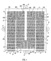
- a main perforated plate 10 for use in the invention is of rectangular shape, having four edges 10A, 10B, 10C, 10D. It has a series of perforations in the form of elongated slots 11 through its thickness.
- the slots 11 lie in parallel rows forming four main groups of rows extending across the plate between edges 10A and 10C. As shown there are 16 rows of slots in each group of rows but it will be appreciated that more or less rows of slots per group (and more or less groups across the plate) may be employed, if desired.
- Transverse bars or flow interrupters 12 separate each slot from adjacent slots in the same row. (It will be appreciated that bars 12, which are shown normally across the plate, could if desired be angled.). Narrow fins or ribs 13 extending in the direction of the slots separate each slot in a row from a slot in an adjacent row.
- An unperforated border region 14 extends around the whole of edges 10B, 10C, 10D of the plate.
- the central portion of edge 10A is also unperforated, but groups of edge slots 15 and 16 corresponding to the first and fourth groups of slots perforate the remainder of edge 10A.
- Positioning lugs 17 are integrally-formed at the mid-region of each edge 10A, 10B, 10C, 10D.
- an L-shaped slot 19A turns its row through a right angle so that the row which ran parallel to edge 10B now continues parallel to side 10C.
- a second L-shaped slot 19B then turns each row through a second right angle so that the rows, now forming the second group of rows, continue back across the plate parallel to edge 10B.
- This pattern is repeated when the second group of rows of slots approaches the border at edge 10A, with L-shaped slots 19C turning the rows to continue parallel to edge 10A and then L-shaped slots 19D turning the rows again to run parallel to edge 10D.
- each row of slots provides a discrete flow channel separated from adjacent flow channels.
- the stack may be bonded in the border regions of the plates 10 by diffusion bonding, without risk of fin collapse.
- a stack will comprise at least two groups of pairs of superposed plates, each group being divided from an adjacent group by an unperforated separator plate. Different fluids can then pass through each group to effect a desired heat exchange.
- plates forming a coolant layer may be positioned adjacent to a group of main perforated plates and be separated therefrom by an unperforated plate whereby coolant fluid or a heating fluid may be passed through the passageways of the coolant layer plates.
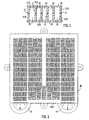
- Plate 20 for use in the invention.
- Plate 20 has a basically similar construction to plate 10 of Figure 1 to provide a four-pass arrangement but slots 21 in the first and second groups of slots are chevron shaped rather than linearly elongate, thereby providing a herringbone pattern of passageways in the first two passes of passes of fluid through a stack containing pairs of plates 20.
- the plate 20 has cross-channel vents 22 through the ribs or fins 23 which separate each slot in a row from a slot in an adjacent row. These vents enable mixing of the fluid to take place at predetermined positions between the otherwise discrete, independent flow channels that are formed when two or more plates 20 are stacked together.
- vents 22 are shown at regular repeating intervals in Figure 2 and are shown in larger scale in Figure 2A where a portion of a fin 23 is shown.
- the vents may be formed by etching through, for example, about half of the rib thickness.
- the pitch a or b of the vents may be variable, if desired. For example, it may be desirable to change the pitch of the vents at the approach to the L-shaped slots.
- Plate 20 also has groups of injection ports 24, 25 and 26 positioned to inject a second and, if desired, third and fourth fluids respectively into a process fluid passing through a stack containing at least a pair of plates 20.
- Injection ports 24 communicate into a row of slots 21A parallel to edge 20C of the plate through border region 27 of the plate.
- Injection ports 25 similarly communicate into a row of slots 21B parallel to edge 20A of the plate and injection ports 26 communicate into a second row of slots 21C parallel to edge 20C.
- Process fluid enters at a first group of slots 28 at edge 20A in the direction of the arrows and makes a first pass across a stack towards edge 20B where it is turned at right angles to run parallel to edge 20C.
- a second fluid can then be injected through ports 24 prior to the fluids then being turned again at right angles to travel back to edge 20A where further fluid which may be the second or a third fluid, can be injected through ports 25.
- the fluids are turned again to travel back towards edge 20C where they are again turned and further fluid injected through ports 26 before the fluids are finally turned to travel again to edge 20A where they exit through slots 29 again in the direction of the arrows.
- entry slots 28 and exit slots 29 are formed attached to integrally-formed opening tabs 30 and 31 respectively.
- These tabs are formed with a weakness, e.g. are etched half-way through their thickness, so that they can be broken off after the desired stack has been formed.
- two or more fluids may be mixed via the injection ports and the cross-channel vents.
- the injection ports 24 were so positioned to allow any initial turbulence of the fluid entering the stack to subside before injection of the second fluid.
- Injection ports 25 are positioned to allow any heat of reaction caused by the injection of the second fluid to be dissipated by a cooling fluid in adjacent plate passageways before further fluid is injected.
- ports 26 are positioned to allow heat dissipation to take place after injection at ports 25 before further injection takes place.
- Figure 3 a group of channels 30 formed by ribs or fins 31 extending across the flow path of a fluid between two unperforated plates 32, 33.
- the ribs 31 are formed by the juxtaposition of ribs 31A and 31B of two perforated plates. As shown the transverse pitch of the ribs is variable.
- the slots in the rows and hence the elongation of the fins may also vary along the length of the rows so that a wide variety of longitudinal and transverse pitch variation is possible.
- a plate 40 has a construction similar to that of Figure 1 with essentially the same arrangement of slots, ribs, bars and borders.
- Loop 41 surrounds and encloses the inlet region A
- loop 42 surrounds and encloses the outlet region B.
- loops 41 stack together and loops 42 stack together to form two integral tanks which are co-extensive with the inlet and outlet regions and through which the inlet region can be fed and into which the outlet can feed.
- the tanks can be fitted with fluid supply and removal means in the conventional manner. It will be appreciated that where intervening plates are used, they too must have integral loops corresponding to those shown in Figure 4.
- FIG 5 a stack 50 having four groups of perforated plates providing four separate passageways through the stack.
- Each group contains an identical array of perforated plates, being at least one pair of superposed plates similar to those shown in Figures 1 or 2, i.e. each group provides a four-pass passageway through the plate for its fluid, i.e. the stack is a four-stream, four-pass arrangement.
- the first group of plates has an inlet at 51 and an outlet at 52 for the first stream.
- the second group has an inlet at 53 and an outlet at 54 for the second stream.
- the third group has an inlet at 55 and an outlet at 56 for the third stream.
- the fourth group has an inlet at 57 and outlet at 58 for the fourth stream.
- Tabs 51A and 52A; 53A and 54A; 55A and 56A; 57A and 58A correspond to the inlets and outlets respectively of the same reference number.
- each group of plates is rotated through 90° clockwise in the stack relative to the group beneath it to achieve the desired construction.
- Figure 6A a stack of plates of the invention particularly suitable for use as a chemical reactor.
- the plates used to make the stack are shown in Figures 6B to 6F.
- plate P represents a group of at least two perforated plates having the rows of slots required to provide the fluid channels needed in the present invention. As shown, the group has a passageway 61 defining a four-pass arrangement between inlet 62 and outlet 63. Process fluid will pass through this group of plates in the stack of Figure 6A.
- Figure 6C is shown a group of plates C having a passageway 64 defining a four-pass arrangement between inlet 65 and outlet 66. Coolant will pass through this group of plates in the stack of Figure 6A and plates C will be, as shown, rotated clockwise through 90° relative to plates P.
- Figure 6D is a group of plates R similar to group P. Again, this group has a passageway 67 defining a four-pass arrangement between an inlet 68 and an outlet 69. Reactant will pass through this group of plates in the stack of Figure 6A. As shown, plates R are rotated clockwise through 90° relative to plates C and 180° relative to plates P.
- Figure 6E shows a single, unperforated intervening separator plate TS.
- Figure 6F shows a single intervening mixing plate TP.
- Plate TP has groups of circular holes TPP through its thickness, although holes of other shapes may be used, if desired.
- the plates or groups of plates are assembled and bonded into a stack in the order shown in Figure 6A. It will be noted that the stack repeats in the sequence TS-P-TP-R-TS-C-TS-P and so on.
- the reactant and process layers are separated by the mixing plate TP whereby the reactant can be mixed into the process layer at the predetermined positions governed by the positions of the groups of holes TPP and in amounts governed by fluid pressure and the size and number of the holes. Coolant fluid passes between adjacent pairs of unperforated plates TS.
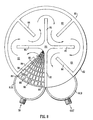
- FIGs 7 and 8 a stack 70 of circular plates is shown.
- the stack has a four-stream, eight-pass construction.
- the four streams A, B, C, D are indicated in Figure 7, each having an inlet, e.g. A (in) and an outlet, e.g. A (out).
- Each inlet and outlet is positioned in an integral tank 71.
- the eight tanks 71 are shown equi-spaced around the perimeter 72 of the circular stack by the superposition of loops formed on the perimeters of the individual plates. (See loops 81A and 81B in Figure 8). However, such equi-spacing is not essential and other tank arrangements may be utilised where desired.
- FIG 8 An individual perforated plate 80 from the stack of Figure 7 is shown in Figure 8.
- the plate has two loops 81A and 81B integrally formed on its perimeter 82 corresponding to the inlet and outlet tanks respectively for the group of plates of which plate 80 is one constituent.
- the plate is divided by radial bars into eight segments 83, each segment corresponding to a loop 81.
- Alternate bars 84 and 85 extend inwardly from the perimeter 82 and outwardly from the centre 86 respectively, bars 84 stopping short of the centre and bars 85 stopping short of the perimeter whereby a continuous passageway 83 is provided between the segments from inlet loop 81A to the outlet loop 81B.
- a bar 87 which divides the segment adjacent inlet loop 81A from outlet loop 81B, extends continuously from the perimeter to the centre, thereby preventing flow between the inlet and outlet segments.
- Each segment 83 of the plate contains rows of perforations 88 separated by fins 89.
- Transverse bars 90 separate the perforations in each row. The perforations and/or fins narrow from the perimeter to the centre.
- the stack 70 is made up of four groups of plates, each containing at least two superposed plates 80, adjacent groups being separated by a solid plate.
- a process group of plates as opposed to a coolant group will also contain a perforated reactant, i.e. mixing, plate.
- the heat transfer and/or mixing effect can be greatly varied to meet a wide range of requirements by adjusting the lengths of the radial bars and the number of rows of perforations per segment.
- the flow velocity v. flow channel width relationship can be adjusted to give a higher degree of turbulence, if required for heat transfer applications.
- the invention can provide a heat exchanger/mixer/reactor in which so-called process intensification can be effectively utilised, i.e. the stack of the invention can be used to control and dissipate the heat produced in an exothermic chemical reaction. It can be used to maintain a more constant reaction temperature at the optimum temperature. It can be used to put in heat, if needed to start a reaction and then to dissipate heat when the heat of reaction builds up.
- the dangers of conventional mixing tanks, i.e. over-heating, and the inconvenience of having to mix small amounts of reactants, hold, stir and then inject further small amounts can be obviated in a much more energy efficient manner.
Landscapes
- Engineering & Computer Science (AREA)
- Physics & Mathematics (AREA)
- Thermal Sciences (AREA)
- Mechanical Engineering (AREA)
- General Engineering & Computer Science (AREA)
- Chemical & Material Sciences (AREA)
- Organic Chemistry (AREA)
- Chemical Kinetics & Catalysis (AREA)
- Heat-Exchange Devices With Radiators And Conduit Assemblies (AREA)
- Engine Equipment That Uses Special Cycles (AREA)
- Physical Or Chemical Processes And Apparatus (AREA)
Claims (16)
- Wärmeaustauscher oder Fluidmischvorrichtung mit einem gebundenen Plattenstapel, der mindestens eine Gruppe (P, R) von perforierten Hauptplatten (10) aufweist, wobei bei mindestens zwei benachbarten Platten (10) der Gruppe (P, R) der perforierten Hauptplatten die Perforationen (11) reihenweise ausgerichtet sind und zwischen benachbarten Reihen kontinuierliche Rippen (13) und zwischen benachbarten Paaren von Perforationsreihen Querträger (12) vorliegen sowie die benachbarten Platten (10) ausgerichtet sind, wobei sich die Reihen der Perforationen (11) in einer Platte (10) in der Richtung der Reihen mit den Reihen der Perforationen (11) einer benachbarten Platte (10) überlappen, wobei die Querträger (12) einer Platte nicht mit jenen einer benachbarten Platte überlappen und die Rippen (13) von benachbarten Platten eine entsprechende gegenseitige Anordnung zueinander haben, um einzelne Fluidkanäle (30) zu bilden, die sich über die Platten hinweg erstrecken, wobei jeder Reihe von Perforationen (11) ein Kanal (30) entspricht und die Kanäle zusammen einen oder mehrere Fluiddurchgänge (61, 67) über die Platten hinweg bilden und der oder die Durchgänge (61) in der Gruppe (P, R) der perforierten Hauptplatten von dem oder den Durchgängen (67) in jeder benachbarten Gruppe (R, P) von perforierten Platten mittels einer dazwischenliegenden Platte (TS) getrennt sind, dadurch gekennzeichnet, daß die dazwischenliegende Platte (TP) durch ihre Dicke hindurch Löcher (TPP) aufweist, deren Größe, Anzahl und Lage derart gewählt sind, daß das Mischen von Fluiden, die durch die Durchgänge hindurchtreten, welche durch die dazwischenliegende Platte (TP) getrennt sind, gesteuert wird.
- Wärmeaustauscher oder Fluidmischvorrichtung nach Anspruch 1, dadurch gekennzeichnet, daß die Perforationen der perforierten Hauptplatten längliche Schlitze (11) sind.
- Wärmeaustauscher oder Fluidmischvorrichtung nach Anspruch 1 oder 2, dadurch gekennzeichnet, daß die Perforationen (11) am Ende einer Perforationareihe derart gestaltet sind, daß sie ihre zugehörigen Kanäle in einem Winkel ablenken, wobei sich die durch die Kanäle festgelegten Durchgänge (61, 67) in einer anderen Richtung fortsetzen.
- Wärmeaustauscher oder Fluidmischvorrichtung nach Anspruch 3, dadurch gekennzeichnet, daß die Perforationen (11) am Ende einer Perforationsreihe "L"- oder "V"-förmig ausgebildet sind.
- Wärmeaustauscher oder Fluidmischvorrichtung nach Anspruch 4, dadurch gekennzeichnet, daß die Platten (10) quadratisch oder rechteckig sind und sich eine Reihe von Schlitzen (11) von einem ersten Rand (10A) der Platte parallel zu einem zweiten Rand (10B) der Platte über im wesentlichen die ganze Länge des zweiten Rands (10B) erstreckt und neben dem dritten Rand (10C) der Platte gegenüber dem Rand (10A) ein erster L-förmiger Schlitz (19A) die Reihe derart abändert, daß sie sich parallel zu dem dritten Rand (10C) erstreckt, und dann ein zweiter L-förmiger Schlitz (19B) die Reihe derart abändert, daß sie sich zurück zum ersten Rand (10A) erstreckt.
- Wärmeaustauscher oder Fluidmischvorrichtung nach einem der Ansprüche 1 bis 3, dadurch gekennzeichnet, daß die Platten (80) kreisförmig sind und die Durchgänge (83) sich vom Außenumfang (82) eines Segments des Kreises zur Mitte (86) hin, über einen Winkel zurück zum Umfang (82) und dann durch einen ähnlichen Winkel zurück zur Mitte (82) usw. erstrecken.
- Wärmeaustauscher oder Fluidmischvorrichtung nach einem der vorstehenden Ansprüche, dadurch gekennzeichnet, daß die Perforationen (11) in den Platten (10) photochemisch durch die Platten hindurchgeätzt worden sind.
- Wärmeaustauscher oder Fluidmischvorrichtung nach einem der vorstehenden Ansprüche, dadurch gekennzeichnet, daß in den festen Bereichen oder Rippen (23), die zwischen benachbarten Reihen von Perforationen (21) der Platten (20) festgelegt sind, Querkanäle oder Austrittsöffnungen (22) ausgebildet sind, wodurch zwischen den Kanälen eines Durchgangs eine Verbindung hergestellt wird.
- Wärmeaustauscher oder Fluidmischvorrichtung nach Anspruch 8, dadurch gekennzeichnet, daß die Kanäle oder Austrittsöffnungen (22) entlang ihren entsprechenden Rippen (23) in veränderbaren Abständen (a, b) angeordnet sind.
- Wärmeaustauscher oder Fluidmischvorrichtung nach einem der vorstehenden Ansprüche, dadurch gekennzeichnet, daß Einlaßöffnungen (24, 25, 26) durch die Umfangsränder 27 einer Platte (20) hindurch ausgebildet sind.
- Wärmeaustauscher oder Fluidmischvorrichtung nach einem der vorstehenden Ansprüche, dadurch gekennzeichnet, daß Platten, die eine Kühlschicht (C) bilden, neben einer ersten oder zweiten Gruppe von Platten (P, R) angeordnet und davon durch eine nichtperforierte Platte (TS) getrennt sind, wobei ein Kühlfluid oder ein Heizfluid durch die Durchgänge der Platten (C) hindurchgeführt werden können.
- Wärmeaustauscher oder Fluidmischvorrichtung nach einem der vorstehenden Ansprüche, dadurch gekennzeichnet, daß die Platten (10, 110) an ihrem Rand Verlängerungen (17, 117) in Form von Laschen aufweisen, um ein Anordnen der Platten beim Stapeln zu unterstützen, wobei die Laschen mit einer Schwächungslinie versehen sind, mit deren Hilfe sie bei Bedarf von den Platten abgebrochen werden können.
- Wärmeaustauscher oder Fluidmischvorrichtung nach einem der vorstehenden Ansprüche, dadurch gekennzeichnet, daß die Platten (20) an ihren Rändern mit einstückig ausgebildeten Vorsprüngen (30, 31) ausgerüstet sind, die sich an Einlaß- und Auslaßöffnungen (28, 29) für die Platten (20) befinden und Schwächungslinien aufweisen, an denen sie bei Bedarf von den Platten abgebrochen werden können.
- Wärmeaustauscher oder Fluidmischvorrichtung nach einem der vorstehenden Ansprüche, dadurch gekennzeichnet, daß die Platten (40, 80) an ihren Rändern mit einer oder mehreren Verlängerungen in Form von Ösen (42, 81A, 81B) aufweisen, die jeweils eine Öffnung am Rand ihrer Platte bilden, wodurch die Öffnungen benachbarter Platten einen oder mehrere Behälter (71) bilden, wenn die Platten gestapelt sind, und die Ein- und Ausläße zu den Durchgängen (83), welche durch die Platten (80) gebildet werden, durch die Behälter (71) hindurch gebildet werden.
- Wärmeaustauscher oder Fluidmischvorrichtung nach einem der vorstehenden Ansprüche, dadurch gekennzeichnet, daß die Platten dünne Metallplaten mit einer Dicke von 0,5 mm oder weniger darstellen und durch Hartlöten oder Diffusionsbindung miteinander verbunden sind.
- Wärmeaustauscher oder Fluidmischvorrichtung nach einem der vorstehenden Ansprüche, dadurch gekennzeichnet, daß die Platten aus Edelstahl, Aluminium, Kupfer, Titan oder Legierungen hiervon bestehen.
Priority Applications (1)
| Application Number | Priority Date | Filing Date | Title |
|---|---|---|---|
| EP01121413A EP1162426B1 (de) | 1997-06-03 | 1998-05-28 | Wärmetauscher und/oder Vorrichtung zur Mischung von Fluiden |
Applications Claiming Priority (5)
| Application Number | Priority Date | Filing Date | Title |
|---|---|---|---|
| GB9711429 | 1997-06-03 | ||
| GBGB9711429.2A GB9711429D0 (en) | 1997-06-03 | 1997-06-03 | Heat exchanger and/or fluid mixing means |
| GBGB9724538.5A GB9724538D0 (en) | 1997-11-20 | 1997-11-20 | Heat exchanger and/or fluid mixing means |
| GB9724538 | 1997-11-20 | ||
| PCT/GB1998/001565 WO1998055812A1 (en) | 1997-06-03 | 1998-05-28 | Heat exchanger and/or fluid mixing means |
Related Child Applications (1)
| Application Number | Title | Priority Date | Filing Date |
|---|---|---|---|
| EP01121413A Division EP1162426B1 (de) | 1997-06-03 | 1998-05-28 | Wärmetauscher und/oder Vorrichtung zur Mischung von Fluiden |
Publications (2)
| Publication Number | Publication Date |
|---|---|
| EP0996847A1 EP0996847A1 (de) | 2000-05-03 |
| EP0996847B1 true EP0996847B1 (de) | 2003-02-19 |
Family
ID=26311642
Family Applications (2)
| Application Number | Title | Priority Date | Filing Date |
|---|---|---|---|
| EP98924469A Expired - Lifetime EP0996847B1 (de) | 1997-06-03 | 1998-05-28 | Wärmetauscher und/oder flüssigkeitsmischvorrichtung |
| EP01121413A Expired - Lifetime EP1162426B1 (de) | 1997-06-03 | 1998-05-28 | Wärmetauscher und/oder Vorrichtung zur Mischung von Fluiden |
Family Applications After (1)
| Application Number | Title | Priority Date | Filing Date |
|---|---|---|---|
| EP01121413A Expired - Lifetime EP1162426B1 (de) | 1997-06-03 | 1998-05-28 | Wärmetauscher und/oder Vorrichtung zur Mischung von Fluiden |
Country Status (8)
| Country | Link |
|---|---|
| US (2) | US6510894B1 (de) |
| EP (2) | EP0996847B1 (de) |
| AT (2) | ATE292779T1 (de) |
| AU (1) | AU7666798A (de) |
| CA (1) | CA2292566A1 (de) |
| DE (2) | DE69811503T2 (de) |
| GB (1) | GB2328275B (de) |
| WO (1) | WO1998055812A1 (de) |
Families Citing this family (78)
| Publication number | Priority date | Publication date | Assignee | Title |
|---|---|---|---|---|
| WO1999066280A1 (en) * | 1998-06-12 | 1999-12-23 | Chart Heat Exchangers Limited | Heat exchanger |
| US6695044B1 (en) | 1999-03-27 | 2004-02-24 | Chart Heat Exchangers Limited Partnership | Heat exchanger |
| US6247529B1 (en) * | 1999-06-25 | 2001-06-19 | Visteon Global Technologies, Inc. | Refrigerant tube for a heat exchanger |
| GB9926466D0 (en) * | 1999-11-10 | 2000-01-12 | Chart Marston Limited | Heat exchanger |
| US7435392B2 (en) | 2000-02-03 | 2008-10-14 | Acclavis, Llc | Scalable continuous production system |
| DE50107530D1 (de) * | 2000-02-14 | 2006-02-09 | Cpc Cellular Process Chemistry | Mikroreaktor mit verbessertem Wärmetauscher |
| DE10024111B4 (de) * | 2000-05-18 | 2006-02-23 | Robert Bosch Gmbh | Verfahren zur Herstellung eines Bauelements aus übereinander gestapelten miteinander verlöteten Platten |
| US7413714B1 (en) | 2000-07-16 | 2008-08-19 | Ymc Co. Ltd. | Sequential reaction system |
| DE10036602A1 (de) * | 2000-07-27 | 2002-02-14 | Cpc Cellular Process Chemistry | Mikroreaktor für Reaktionen zwischen Gasen und Flüssigkeiten |
| DE10044526A1 (de) * | 2000-09-04 | 2002-04-04 | Mannesmann Ag | Mikrostrukturreaktor und Verfahren zur Durchführung chemischer Reaktionen |
| GB2372948A (en) | 2000-10-31 | 2002-09-11 | Chart Heat Exchangers Ltd | A bonded stack of plates forming a heat exchanger and/or fluid mixing apparatus |
| GB0028410D0 (en) | 2000-11-22 | 2001-01-03 | Chart Heat Exchangers Ltd | Heat exchanger and chemical reactor |
| GB0030201D0 (en) | 2000-12-12 | 2001-01-24 | Chart Heat Exchangers Ltd | Heat exchanger |
| GB0100357D0 (en) * | 2001-01-06 | 2001-02-14 | Chart Heat Exchangers Ltd | Heat exchanger/chemical reactor |
| DE10102726A1 (de) * | 2001-01-22 | 2002-08-22 | Vodafone Pilotentwicklung Gmbh | Reaktor |
| GB0114361D0 (en) * | 2001-06-13 | 2001-08-08 | Chart Heat Exchangers Ltd | Heat exchanger |
| GB0118858D0 (en) | 2001-08-02 | 2001-09-26 | Dow Corning | Hydrosilylation process |
| FI113695B (fi) * | 2001-10-09 | 2004-05-31 | Vahterus Oy | Hitsattu levyrakenteinen lämmönvaihdin |
| US6856037B2 (en) * | 2001-11-26 | 2005-02-15 | Sony Corporation | Method and apparatus for converting dissipated heat to work energy |
| WO2003095925A1 (en) * | 2002-05-10 | 2003-11-20 | George Sandor Viczena | Control of air conditioning cooling or heating coil |
| US7014835B2 (en) | 2002-08-15 | 2006-03-21 | Velocys, Inc. | Multi-stream microchannel device |
| US6622519B1 (en) | 2002-08-15 | 2003-09-23 | Velocys, Inc. | Process for cooling a product in a heat exchanger employing microchannels for the flow of refrigerant and product |
| GB0220652D0 (en) * | 2002-09-05 | 2002-10-16 | Chart Heat Exchangers Ltd | Heat exchanger |
| US7101515B2 (en) | 2003-04-14 | 2006-09-05 | Cellular Process Chemistry, Inc. | System and method for determining optimal reaction parameters using continuously running process |
| US7294734B2 (en) | 2003-05-02 | 2007-11-13 | Velocys, Inc. | Process for converting a hydrocarbon to an oxygenate or a nitrile |
| US7220390B2 (en) | 2003-05-16 | 2007-05-22 | Velocys, Inc. | Microchannel with internal fin support for catalyst or sorption medium |
| WO2004103539A2 (en) | 2003-05-16 | 2004-12-02 | Velocys Inc. | Process for forming an emulsion using microchannel process technology |
| US7485671B2 (en) | 2003-05-16 | 2009-02-03 | Velocys, Inc. | Process for forming an emulsion using microchannel process technology |
| JP4248931B2 (ja) * | 2003-05-20 | 2009-04-02 | カルソニックカンセイ株式会社 | 熱交換器 |
| JP4587016B2 (ja) * | 2003-05-30 | 2010-11-24 | ソニー株式会社 | 反応装置とその製造方法、改質装置、電源供給システム |
| US7029647B2 (en) | 2004-01-27 | 2006-04-18 | Velocys, Inc. | Process for producing hydrogen peroxide using microchannel technology |
| US7084180B2 (en) | 2004-01-28 | 2006-08-01 | Velocys, Inc. | Fischer-tropsch synthesis using microchannel technology and novel catalyst and microchannel reactor |
| US9023900B2 (en) | 2004-01-28 | 2015-05-05 | Velocys, Inc. | Fischer-Tropsch synthesis using microchannel technology and novel catalyst and microchannel reactor |
| WO2005121682A1 (de) * | 2004-06-07 | 2005-12-22 | Hartmann, Eva | Wärmetransporteinrichtung |
| US7305850B2 (en) | 2004-07-23 | 2007-12-11 | Velocys, Inc. | Distillation process using microchannel technology |
| EP1781389A2 (de) | 2004-07-23 | 2007-05-09 | Velocys, Inc. | Destillationsverfahren mit hilfe von mikrokanal-technologie |
| JP2006122736A (ja) * | 2004-10-26 | 2006-05-18 | Dainippon Screen Mfg Co Ltd | 流路構造体およびその製造方法 |
| EP1817102A1 (de) | 2004-11-12 | 2007-08-15 | Velocys, Inc. | Verfahren unter verwendung von mikrokanaltechnologie zur durchführung einer alkylierungs- oder acylierungsreaktion |
| GB0509747D0 (en) * | 2005-05-13 | 2005-06-22 | Ashe Morris Ltd | Variable volume heat exchangers |
| EP1890802A2 (de) | 2005-05-25 | 2008-02-27 | Velocys, Inc. | Träger zur verwendung bei der mikrokanalverarbeitung |
| GB2428780A (en) * | 2005-07-27 | 2007-02-07 | John Rhys Jones | Perforated plate heat exchanger |
| GT200600392A (es) * | 2005-08-31 | 2007-09-25 | Produccion por auto-oxidacion de peroxido de hidrogeno a traves de hidrogenacion en un microreactor | |
| WO2007027785A2 (en) * | 2005-08-31 | 2007-03-08 | Fmc Corporation | Auto-oxidation production of hydrogen peroxide via oxidation in a microreactor |
| SE529516C2 (sv) * | 2005-10-24 | 2007-09-04 | Alfa Laval Corp Ab | Universell flödesmodul |
| FR2896576B1 (fr) * | 2006-01-20 | 2008-04-18 | Alfa Laval Packinox Soc Par Ac | Installation d'echange thermique a faisceaux de plaques |
| CA2648589C (en) * | 2006-04-07 | 2015-10-20 | Chart Industries, Inc. | Supercritical process, reactor and system for hydrogen production |
| WO2008112999A1 (en) * | 2007-03-15 | 2008-09-18 | Fmc Corporation | Recovery of aqueous hydrogen peroxide in auto-oxidation h2o2 production |
| US20080296354A1 (en) * | 2007-05-31 | 2008-12-04 | Mark Crockett | Stainless steel or stainless steel alloy for diffusion bonding |
| US7798388B2 (en) * | 2007-05-31 | 2010-09-21 | Applied Materials, Inc. | Method of diffusion bonding a fluid flow apparatus |
| JP5643088B2 (ja) * | 2007-07-09 | 2014-12-17 | チャート・インダストリーズ・インコーポレーテッド | プレートフィン式流体処理装置 |
| US8438835B2 (en) * | 2007-07-30 | 2013-05-14 | General Electric Company | Methods and apparatus for mixing fluid in turbine engines |
| US8516791B2 (en) * | 2007-07-30 | 2013-08-27 | General Electric Company | Methods and apparatus for mixing fluid in turbine engines |
| US20090113796A1 (en) * | 2007-11-07 | 2009-05-07 | Battelle Memorial Institute | Compact, space-saving arrangement of microchannel steam reforming reactors with improved performance |
| DE102007054071B4 (de) * | 2007-11-13 | 2010-06-10 | Eisfink Max Maier Gmbh & Co. Kg | Verbundmetallgegenstand und Verfahren zur Herstellung eines Verbundmetallgegenstands |
| AT506358B1 (de) * | 2008-02-07 | 2009-11-15 | Gerhard Dr Kunze | Einfache für massenproduktion geeignete bauweise für komplexe hydropneumatische systeme |
| US8075645B2 (en) * | 2008-04-08 | 2011-12-13 | Chart Inc. | Catalysts, system and method for hydrogen production |
| DE102008029096B4 (de) * | 2008-06-20 | 2010-04-15 | Voith Patent Gmbh | Verdampfer für ein Abwärmenutzungssystem |
| JP5773353B2 (ja) * | 2011-02-15 | 2015-09-02 | 忠元 誠 | 熱交換器 |
| US9921000B2 (en) | 2011-07-22 | 2018-03-20 | 8 Rivers Capital, Llc | Heat exchanger comprising one or more plate assemblies with a plurality of interconnected channels and related method |
| US8869398B2 (en) * | 2011-09-08 | 2014-10-28 | Thermo-Pur Technologies, LLC | System and method for manufacturing a heat exchanger |
| WO2013075143A1 (en) * | 2011-11-18 | 2013-05-23 | Chart Industries, Inc. | Core in kettle reactor, methods for using, and methods of making |
| GB201214122D0 (en) | 2012-08-07 | 2012-09-19 | Oxford Catalysts Ltd | Treating of catalyst support |
| CA2826962C (en) * | 2012-10-11 | 2021-01-05 | Yves De Vos | Combined heat exchanging and fluid mixing apparatus |
| US9206091B2 (en) * | 2013-05-14 | 2015-12-08 | Chevron U.S.A. Inc. | Processes and systems for synthesis gas conversion using a hybrid fischer-tropsch catalyst in a compact heat exchange reactor |
| JP6190349B2 (ja) * | 2013-12-05 | 2017-08-30 | 株式会社神戸製鋼所 | 熱交換器 |
| FR3022398B1 (fr) * | 2014-06-13 | 2019-01-25 | Safran Aircraft Engines | Structure et procede de fabrication ameliores pour une plaque bipolaire de pile a combustible |
| EP3183524B1 (de) * | 2014-08-22 | 2020-11-04 | Mohawk Innovative Technology Inc. | Wärmetauscher mit hoher effektivität und geringem druckverlust |
| US10088239B2 (en) * | 2015-05-28 | 2018-10-02 | Hamilton Sundstrand Corporation | Heat exchanger with improved flow at mitered corners |
| WO2016201218A2 (en) | 2015-06-12 | 2016-12-15 | Velocys, Inc. | Synthesis gas conversion process |
| DE102015110974B4 (de) * | 2015-07-07 | 2022-11-10 | Halla Visteon Climate Control Corporation | Abgaswärmeübertrager mit mehreren Wärmeübertragerkanälen |
| US10619936B2 (en) * | 2016-01-27 | 2020-04-14 | Hamilton Sundstrand Corporation | High pressure counterflow heat exchanger |
| FR3048769B1 (fr) | 2016-03-14 | 2019-05-17 | Commissariat A L'energie Atomique Et Aux Energies Alternatives | Procede de fabrication d'au moins un echangeur de chaleur a plaques par superposition de plaques avec motifs d'alignement |
| JP6718806B2 (ja) * | 2016-12-14 | 2020-07-08 | 株式会社神戸製鋼所 | 流体流通装置 |
| JP6746234B2 (ja) * | 2017-01-25 | 2020-08-26 | 日立ジョンソンコントロールズ空調株式会社 | 熱交換器、及び、空気調和機 |
| US20190024982A1 (en) * | 2017-07-24 | 2019-01-24 | Hamilton Sundstrand Corporation | Heat exchanger assembly with parting sheet support |
| US11268877B2 (en) | 2017-10-31 | 2022-03-08 | Chart Energy & Chemicals, Inc. | Plate fin fluid processing device, system and method |
| CN109751900B (zh) * | 2017-11-03 | 2020-10-16 | 斗山重工业建设有限公司 | 包括一体型结构的印刷电路板式热交换器 |
| CN111893991A (zh) * | 2020-07-04 | 2020-11-06 | 山东省水电设备厂 | 基于回转齿耙式清污机的灌注桩基清污系统 |
Family Cites Families (25)
| Publication number | Priority date | Publication date | Assignee | Title |
|---|---|---|---|---|
| NL80122C (de) | 1948-07-24 | |||
| US3042382A (en) * | 1957-10-31 | 1962-07-03 | Parsons C A & Co Ltd | Plate type heat exchangers |
| GB868244A (en) | 1958-04-18 | 1961-05-17 | Air Preheater | Heat exchanger |
| DE2007033C3 (de) | 1970-02-17 | 1979-06-21 | Hoechst Ag, 6000 Frankfurt | Plattenwärmetauscher aus Polytetrafluorethylen |
| GB1484124A (en) * | 1974-11-21 | 1977-08-24 | Ass Eng Ltd | Heat exchangers |
| US3983191A (en) | 1975-11-10 | 1976-09-28 | The Trane Company | Brazed plate-type heat exchanger for nonadiabatic rectification |
| US4214867A (en) | 1978-07-18 | 1980-07-29 | Matthey Bishop, Inc. | Method and apparatus for catalytic heat exchange |
| FR2500610B1 (fr) | 1981-02-25 | 1986-05-02 | Inst Francais Du Petrole | Echangeur de chaleur a plaques perforees |
| DE3220774C2 (de) * | 1982-06-02 | 1986-09-25 | W. Schmidt GmbH & Co KG, 7518 Bretten | Plattenverdampfer oder -kondensator |
| US4516632A (en) | 1982-08-31 | 1985-05-14 | The United States Of America As Represented By The United States Deparment Of Energy | Microchannel crossflow fluid heat exchanger and method for its fabrication |
| JPS60256794A (ja) * | 1984-06-04 | 1985-12-18 | Mitsubishi Electric Corp | 熱交換システム |
| US4880055A (en) * | 1988-12-07 | 1989-11-14 | Sundstrand Corporation | Impingement plate type heat exchanger |
| GB2251679B (en) | 1989-05-04 | 1993-12-15 | Secretary Trade Ind Brit | Heat exchangers |
| US5016707A (en) * | 1989-12-28 | 1991-05-21 | Sundstrand Corporation | Multi-pass crossflow jet impingement heat exchanger |
| DE4022654A1 (de) * | 1990-07-17 | 1992-01-23 | Hoechst Ag | Karte aus keramischem material zum aufbau von durchlaessigen strukturen |
| JP3512186B2 (ja) | 1993-03-19 | 2004-03-29 | イー・アイ・デユポン・ドウ・ヌムール・アンド・カンパニー | 化学処理及び製造のための一体構造及び方法、並びにその使用方法及び製造方法 |
| JP3364665B2 (ja) * | 1993-03-26 | 2003-01-08 | 昭和電工株式会社 | 熱交換器用冷媒流通管 |
| FR2718836B1 (fr) | 1994-04-15 | 1996-05-24 | Maurice Grenier | Echangeur de chaleur perfectionné à plaques brasées. |
| US6129973A (en) | 1994-07-29 | 2000-10-10 | Battelle Memorial Institute | Microchannel laminated mass exchanger and method of making |
| US5811062A (en) | 1994-07-29 | 1998-09-22 | Battelle Memorial Institute | Microcomponent chemical process sheet architecture |
| US5611214A (en) | 1994-07-29 | 1997-03-18 | Battelle Memorial Institute | Microcomponent sheet architecture |
| IT1277154B1 (it) * | 1995-01-27 | 1997-11-04 | Diana Giacometti | Scambiatore di calore e di materia a piastre piane. |
| NL1000218C2 (nl) * | 1995-04-25 | 1996-10-28 | Stichting Energie | Fluïdumverdeelinrichting. |
| DE19528116B4 (de) * | 1995-08-01 | 2007-02-15 | Behr Gmbh & Co. Kg | Wärmeübertrager mit Platten-Sandwichstruktur |
| DE19536115C2 (de) | 1995-09-28 | 2001-03-08 | Behr Gmbh & Co | Mehrfluid-Wärmeübertrager mit Plattenstapelaufbau |
-
1998
- 1998-05-28 AT AT01121413T patent/ATE292779T1/de not_active IP Right Cessation
- 1998-05-28 GB GB9811363A patent/GB2328275B/en not_active Expired - Lifetime
- 1998-05-28 DE DE69811503T patent/DE69811503T2/de not_active Expired - Lifetime
- 1998-05-28 CA CA002292566A patent/CA2292566A1/en not_active Abandoned
- 1998-05-28 DE DE69829697T patent/DE69829697T2/de not_active Expired - Lifetime
- 1998-05-28 US US09/445,150 patent/US6510894B1/en not_active Expired - Lifetime
- 1998-05-28 EP EP98924469A patent/EP0996847B1/de not_active Expired - Lifetime
- 1998-05-28 AU AU76667/98A patent/AU7666798A/en not_active Abandoned
- 1998-05-28 WO PCT/GB1998/001565 patent/WO1998055812A1/en active IP Right Grant
- 1998-05-28 AT AT98924469T patent/ATE232962T1/de not_active IP Right Cessation
- 1998-05-28 EP EP01121413A patent/EP1162426B1/de not_active Expired - Lifetime
-
2002
- 2002-12-04 US US10/309,210 patent/US6736201B2/en not_active Expired - Lifetime
Also Published As
| Publication number | Publication date |
|---|---|
| EP0996847A1 (de) | 2000-05-03 |
| US20030079870A1 (en) | 2003-05-01 |
| GB2328275B (en) | 2000-08-16 |
| WO1998055812A1 (en) | 1998-12-10 |
| US6736201B2 (en) | 2004-05-18 |
| GB9811363D0 (en) | 1998-07-22 |
| DE69811503D1 (de) | 2003-03-27 |
| ATE232962T1 (de) | 2003-03-15 |
| DE69829697D1 (de) | 2005-05-12 |
| ATE292779T1 (de) | 2005-04-15 |
| GB2328275A (en) | 1999-02-17 |
| CA2292566A1 (en) | 1998-12-10 |
| EP1162426A2 (de) | 2001-12-12 |
| EP1162426B1 (de) | 2005-04-06 |
| EP1162426A3 (de) | 2002-04-17 |
| DE69829697T2 (de) | 2006-03-09 |
| AU7666798A (en) | 1998-12-21 |
| DE69811503T2 (de) | 2004-06-09 |
| US6510894B1 (en) | 2003-01-28 |
Similar Documents
| Publication | Publication Date | Title |
|---|---|---|
| EP0996847B1 (de) | Wärmetauscher und/oder flüssigkeitsmischvorrichtung | |
| EP1166026B1 (de) | Wärmetauscher | |
| EP1086349B1 (de) | Wärmetauscher | |
| US20060076127A1 (en) | Catalytic Reactor | |
| EP2972043B1 (de) | Gegenstromwärmetauscher/reaktor | |
| EP1137904A1 (de) | Wärmetauscher | |
| JP4504817B2 (ja) | 反応器チャンバ用の流れ方向付けインサートおよび反応器 | |
| EA005643B1 (ru) | Аппарат для проведения реакций для ввода реагентов в контакт с катализатором при непрямом нагревании реагентов в реакционной зоне под действием непрямого теплообмена с теплоносителем (варианты) | |
| US11747088B2 (en) | Compact heat exchanger with alternating fluid channels | |
| GB2333351A (en) | Heat exchanger and/or fluid mixing means | |
| CA2522153A1 (en) | Mixing device | |
| WO2002037047A1 (en) | Heat exchanger and/or fluid mixing means | |
| EP0866940B1 (de) | Wärmetauscher | |
| GB2338293A (en) | Pin fin heat exchanger | |
| WO2002047808A1 (en) | Heat exchanger/chemical reactor | |
| WO2002058840A1 (en) | Chemical reactor | |
| WO2001090672A1 (en) | Heat exchanger |
Legal Events
| Date | Code | Title | Description |
|---|---|---|---|
| PUAI | Public reference made under article 153(3) epc to a published international application that has entered the european phase |
Free format text: ORIGINAL CODE: 0009012 |
|
| 17P | Request for examination filed |
Effective date: 19991222 |
|
| AK | Designated contracting states |
Kind code of ref document: A1 Designated state(s): AT BE CH DE ES FR IE IT LI NL SE |
|
| RAP1 | Party data changed (applicant data changed or rights of an application transferred) |
Owner name: CHART HEAT EXCHANGERS LIMITED |
|
| RBV | Designated contracting states (corrected) |
Designated state(s): AT BE CH DE ES FR IE IT LI NL SE |
|
| 17Q | First examination report despatched |
Effective date: 20000921 |
|
| GRAG | Despatch of communication of intention to grant |
Free format text: ORIGINAL CODE: EPIDOS AGRA |
|
| GRAG | Despatch of communication of intention to grant |
Free format text: ORIGINAL CODE: EPIDOS AGRA |
|
| GRAH | Despatch of communication of intention to grant a patent |
Free format text: ORIGINAL CODE: EPIDOS IGRA |
|
| GRAH | Despatch of communication of intention to grant a patent |
Free format text: ORIGINAL CODE: EPIDOS IGRA |
|
| GRAA | (expected) grant |
Free format text: ORIGINAL CODE: 0009210 |
|
| AK | Designated contracting states |
Designated state(s): AT BE CH DE ES FR IE IT LI NL SE |
|
| PG25 | Lapsed in a contracting state [announced via postgrant information from national office to epo] |
Ref country code: NL Free format text: LAPSE BECAUSE OF FAILURE TO SUBMIT A TRANSLATION OF THE DESCRIPTION OR TO PAY THE FEE WITHIN THE PRESCRIBED TIME-LIMIT Effective date: 20030219 Ref country code: LI Free format text: LAPSE BECAUSE OF FAILURE TO SUBMIT A TRANSLATION OF THE DESCRIPTION OR TO PAY THE FEE WITHIN THE PRESCRIBED TIME-LIMIT Effective date: 20030219 Ref country code: IT Free format text: LAPSE BECAUSE OF FAILURE TO SUBMIT A TRANSLATION OF THE DESCRIPTION OR TO PAY THE FEE WITHIN THE PRESCRIBED TIME-LIMIT;WARNING: LAPSES OF ITALIAN PATENTS WITH EFFECTIVE DATE BEFORE 2007 MAY HAVE OCCURRED AT ANY TIME BEFORE 2007. THE CORRECT EFFECTIVE DATE MAY BE DIFFERENT FROM THE ONE RECORDED. Effective date: 20030219 Ref country code: FR Free format text: LAPSE BECAUSE OF NON-PAYMENT OF DUE FEES Effective date: 20030219 Ref country code: CH Free format text: LAPSE BECAUSE OF FAILURE TO SUBMIT A TRANSLATION OF THE DESCRIPTION OR TO PAY THE FEE WITHIN THE PRESCRIBED TIME-LIMIT Effective date: 20030219 Ref country code: BE Free format text: LAPSE BECAUSE OF FAILURE TO SUBMIT A TRANSLATION OF THE DESCRIPTION OR TO PAY THE FEE WITHIN THE PRESCRIBED TIME-LIMIT Effective date: 20030219 |
|
| REG | Reference to a national code |
Ref country code: CH Ref legal event code: EP |
|
| REG | Reference to a national code |
Ref country code: IE Ref legal event code: FG4D |
|
| REF | Corresponds to: |
Ref document number: 69811503 Country of ref document: DE Date of ref document: 20030327 Kind code of ref document: P |
|
| PG25 | Lapsed in a contracting state [announced via postgrant information from national office to epo] |
Ref country code: SE Free format text: LAPSE BECAUSE OF FAILURE TO SUBMIT A TRANSLATION OF THE DESCRIPTION OR TO PAY THE FEE WITHIN THE PRESCRIBED TIME-LIMIT Effective date: 20030519 |
|
| PG25 | Lapsed in a contracting state [announced via postgrant information from national office to epo] |
Ref country code: IE Free format text: LAPSE BECAUSE OF NON-PAYMENT OF DUE FEES Effective date: 20030528 |
|
| PGFP | Annual fee paid to national office [announced via postgrant information from national office to epo] |
Ref country code: FR Payment date: 20030619 Year of fee payment: 6 |
|
| NLV1 | Nl: lapsed or annulled due to failure to fulfill the requirements of art. 29p and 29m of the patents act | ||
| REG | Reference to a national code |
Ref country code: FR Ref legal event code: RN |
|
| PG25 | Lapsed in a contracting state [announced via postgrant information from national office to epo] |
Ref country code: ES Free format text: LAPSE BECAUSE OF FAILURE TO SUBMIT A TRANSLATION OF THE DESCRIPTION OR TO PAY THE FEE WITHIN THE PRESCRIBED TIME-LIMIT Effective date: 20030828 |
|
| REG | Reference to a national code |
Ref country code: CH Ref legal event code: PL |
|
| REG | Reference to a national code |
Ref country code: FR Ref legal event code: FC |
|
| EN | Fr: translation not filed | ||
| ET | Fr: translation filed | ||
| PLBE | No opposition filed within time limit |
Free format text: ORIGINAL CODE: 0009261 |
|
| STAA | Information on the status of an ep patent application or granted ep patent |
Free format text: STATUS: NO OPPOSITION FILED WITHIN TIME LIMIT |
|
| EN | Fr: translation not filed | ||
| 26N | No opposition filed |
Effective date: 20031120 |
|
| REG | Reference to a national code |
Ref country code: IE Ref legal event code: MM4A |
|
| REG | Reference to a national code |
Ref country code: FR Ref legal event code: TP |
|
| PGFP | Annual fee paid to national office [announced via postgrant information from national office to epo] |
Ref country code: AT Payment date: 20070531 Year of fee payment: 10 |
|
| PG25 | Lapsed in a contracting state [announced via postgrant information from national office to epo] |
Ref country code: AT Free format text: LAPSE BECAUSE OF NON-PAYMENT OF DUE FEES Effective date: 20080528 |
|
| REG | Reference to a national code |
Ref country code: FR Ref legal event code: EERR Free format text: CORRECTION DE BOPI 06/42 - 3.2. Ref country code: FR Ref legal event code: EERR Free format text: CORRECTION DE BOPI 04/02 - 3.2. |
|
| REG | Reference to a national code |
Ref country code: FR Ref legal event code: ST Effective date: 20111202 |
|
| PGFP | Annual fee paid to national office [announced via postgrant information from national office to epo] |
Ref country code: DE Payment date: 20170530 Year of fee payment: 20 |
|
| REG | Reference to a national code |
Ref country code: DE Ref legal event code: R071 Ref document number: 69811503 Country of ref document: DE |