EP0995126B1 - Kraftfahrzeug-radarsystem - Google Patents
Kraftfahrzeug-radarsystem Download PDFInfo
- Publication number
- EP0995126B1 EP0995126B1 EP98941254A EP98941254A EP0995126B1 EP 0995126 B1 EP0995126 B1 EP 0995126B1 EP 98941254 A EP98941254 A EP 98941254A EP 98941254 A EP98941254 A EP 98941254A EP 0995126 B1 EP0995126 B1 EP 0995126B1
- Authority
- EP
- European Patent Office
- Prior art keywords
- oscillator
- radar system
- transistor
- housing
- frequency
- Prior art date
- Legal status (The legal status is an assumption and is not a legal conclusion. Google has not performed a legal analysis and makes no representation as to the accuracy of the status listed.)
- Expired - Lifetime
Links
- 230000001105 regulatory effect Effects 0.000 claims description 2
- 238000010438 heat treatment Methods 0.000 description 13
- 230000005540 biological transmission Effects 0.000 description 5
- 230000010355 oscillation Effects 0.000 description 3
- 101150027978 UMOD gene Proteins 0.000 description 2
- 239000004020 conductor Substances 0.000 description 2
- 230000008878 coupling Effects 0.000 description 2
- 238000010168 coupling process Methods 0.000 description 2
- 238000005859 coupling reaction Methods 0.000 description 2
- 238000010276 construction Methods 0.000 description 1
- 230000001419 dependent effect Effects 0.000 description 1
- 238000001514 detection method Methods 0.000 description 1
- 238000010292 electrical insulation Methods 0.000 description 1
- 230000007613 environmental effect Effects 0.000 description 1
- 238000009472 formulation Methods 0.000 description 1
- 239000002184 metal Substances 0.000 description 1
- 238000000034 method Methods 0.000 description 1
- 239000000203 mixture Substances 0.000 description 1
- 239000004065 semiconductor Substances 0.000 description 1
- 239000000758 substrate Substances 0.000 description 1
- 239000013589 supplement Substances 0.000 description 1
- 230000029305 taxis Effects 0.000 description 1
- 238000010792 warming Methods 0.000 description 1
Images

Classifications
-
- H—ELECTRICITY
- H03—ELECTRONIC CIRCUITRY
- H03B—GENERATION OF OSCILLATIONS, DIRECTLY OR BY FREQUENCY-CHANGING, BY CIRCUITS EMPLOYING ACTIVE ELEMENTS WHICH OPERATE IN A NON-SWITCHING MANNER; GENERATION OF NOISE BY SUCH CIRCUITS
- H03B9/00—Generation of oscillations using transit-time effects
- H03B9/12—Generation of oscillations using transit-time effects using solid state devices, e.g. Gunn-effect devices
-
- G—PHYSICS
- G01—MEASURING; TESTING
- G01S—RADIO DIRECTION-FINDING; RADIO NAVIGATION; DETERMINING DISTANCE OR VELOCITY BY USE OF RADIO WAVES; LOCATING OR PRESENCE-DETECTING BY USE OF THE REFLECTION OR RERADIATION OF RADIO WAVES; ANALOGOUS ARRANGEMENTS USING OTHER WAVES
- G01S7/00—Details of systems according to groups G01S13/00, G01S15/00, G01S17/00
- G01S7/02—Details of systems according to groups G01S13/00, G01S15/00, G01S17/00 of systems according to group G01S13/00
- G01S7/03—Details of HF subsystems specially adapted therefor, e.g. common to transmitter and receiver
- G01S7/032—Constructional details for solid-state radar subsystems
-
- G—PHYSICS
- G01—MEASURING; TESTING
- G01S—RADIO DIRECTION-FINDING; RADIO NAVIGATION; DETERMINING DISTANCE OR VELOCITY BY USE OF RADIO WAVES; LOCATING OR PRESENCE-DETECTING BY USE OF THE REFLECTION OR RERADIATION OF RADIO WAVES; ANALOGOUS ARRANGEMENTS USING OTHER WAVES
- G01S13/00—Systems using the reflection or reradiation of radio waves, e.g. radar systems; Analogous systems using reflection or reradiation of waves whose nature or wavelength is irrelevant or unspecified
- G01S13/88—Radar or analogous systems specially adapted for specific applications
- G01S13/93—Radar or analogous systems specially adapted for specific applications for anti-collision purposes
- G01S13/931—Radar or analogous systems specially adapted for specific applications for anti-collision purposes of land vehicles
Definitions
- the present invention relates to a motor vehicle radar system, with an oscillator, which during the operation of the Radar system depending on a control signal only periodically generates a high frequency signal and one Microwave diode, especially a Gunn or Impatt diode includes housed within a housing-like body is.
- a generic radar system is for example from the WO97 / 02496 known.
- a monostatic FMCW radar sensor for a vehicle for the detection of Objects with at least one antenna feed in Connection with a dielectric lens for both transmission and also designed to receive a corresponding echo signal is.
- This generic radar system is as follows described in more detail with reference to Figures 1 and 2.
- the transmission power of the Oscillators are blanked out to the average energy expenditure or in other words the middle one emitted To reduce microwave transmission power.
- Approaching this the mode of operation of this FMCW radar sensor is one Pulse radar. This takes place in a specific application Blanking of the oscillator, for example in a clock ratio from 90 milliseconds pause to 10 milliseconds each Airtime.
- the oscillator 5 lies according to FIG Figure 4 in series with a control transistor 40 and forms this one voltage divider.
- the Operating voltage Uosz at the oscillator whose momentary Vibration frequency influenced within certain ranges can be, can thus both the transistor Frequency modulation as well as the blanking of the oscillator Taxes.
- the transistor Frequency modulation as well as the blanking of the oscillator Taxes.
- the oscillator contains a microwave diode.
- Such oscillators based on semiconductor components have the property that at very low temperatures, especially below -20 ° C, however, as in a Use in a motor vehicle can occur swing very poorly or not at all. this applies especially since due to the clocked mode of operation Self-heating of the oscillator is not sufficient in this To ensure a safe and frequency-precise start-up.
- a possible solution to this difficulty would be the oscillator permanently at such low temperatures To take operation. However, this either leads to one higher environmental impact due to the then overall increased average transmission power or to an increased Effort to avoid this increased burden.
- the aim of the present invention is to provide a motor vehicle radar system specify where simple and above all Inexpensive way is guaranteed that the oscillator even at very low temperatures and with clocked Operating mode swings up safely and reliably.
- this object is achieved by a radar system solved, in which at least one of the components is ohmic Resistor, transistor or IC body is arranged so that it the case-like body or one with this thermally connected element touches, said component at least within the circuit arrangement of the radar system another function than the generation of heat has.
- a radar system solved in which at least one of the components is ohmic Resistor, transistor or IC body is arranged so that it the case-like body or one with this thermally connected element touches, said component at least within the circuit arrangement of the radar system another function than the generation of heat has.
- the one with the case-like body thermally connected element can for example be a waveguide continuation of the oscillator or a heat sink
- the housing-like body or the body thermally connected to it Element is attached.
- the component mentioned is a transistor, which as a means of adjusting the size of the Control signal of the oscillator is used.
- the advantage of the radar system according to the invention is that self-heating of the oscillator in a very inexpensive way is reinforced since no additional components or circuit measures are needed. Besides, no additional Heating energy required so that the power consumption of the Radar system according to the invention compared to known systems is unchanged. Nevertheless is due to the invention reliable and frequency-precise oscillation of the oscillator guaranteed even at very low temperatures. Opposite one alternatively conceivable continuous operation of the oscillator at very low temperatures is the average emitted microwave power significantly reduced.
- FIG. 1 shows the sketch of a radar system according to the above mentioned prior art.
- a stripline arrangement 1 there are three transmitting / receiving elements 2, 3, 4, which in conjunction with a dielectric lens 9 three Form transmission / reception lobes L, M, R.
- the stripline arrangement 1 is applied to a substrate 8, which in turn is arranged on a base plate 11.
- 5 denotes an oscillator, the construction of which is based on Figure 2 is described in more detail.
- With 6 is one called so-called step transformer. This is a Waveguide arrangement with a narrowing cross section for coupling the microwave energy of the oscillator 5 to the stripline arrangement 1.
- With 7 is a frequency control network designated with which the instantaneous frequency of the Oscillator 5 is adjustable. This is needed because of it
- This radar system described is an FMCW radar is.
- the invention can also independently a pulse radar find application.
- the entire circuit arrangement of the radar system is accommodated in a housing 10, the forward in the beam direction by a di
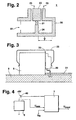
- FIG. 2 shows a known structure of the oscillator 5, such as he for example in "Handbook for radio frequency and Electrical Engineer ", Volume 5, edited by Curt Rind in Weghig-Verlag, Heidelberg is described in more detail.
- a microwave diode preferably one Gunn or Impatt diode 21 within a resonance arrangement 20.
- the resonance arrangement 20 is a waveguide structure, whose geometric dimensions are the resonance frequency of the Determined oscillator.
- an opening 22 is provided, which in the present Case coupled to the step transformer 6 becomes.
- other known types of decoupling are also possible, for example with a magnetic coupling Possible with the help of a conductor loop.
- the microwave diode 21 sits on a cylindrical metal post in this case, which is located in the middle of the resonance arrangement 20. With it touches a metallic block 23 at its upper end.
- a Operating voltage can be supplied. Exceeds this operating voltage a threshold, the size of which is used Diode type depends, is within the resonance assembly 20 a high-frequency vibration is excited, the frequency in essentially due to the geometric dimensions of the arrangement is determined. By varying the size of the supply voltage however, the frequency can be within one certain range. This will be one FMCW radar advantageously used for frequency modulation. If the operating voltage falls below the mentioned Threshold, the excited oscillation subsides, that is called the oscillator 5 stops vibrating. In cycle operation becomes the supply voltage for blanking the oscillator usually set to zero.
- FIG. 3 shows a preferred arrangement according to the invention of a transistor to supplement the self-heating of the Oscillator 5.
- a transistor instead of the transistor an ohmic resistor, an integrated circuit (IC) or another component used become. It is essential that this is a component is a measurable in operation and for the named Has sufficient self-heating purpose.
- 31 denotes a conductor track, which makes contact with transistor 30, for example is.
- the transistor 30 touches the oscillator 5 and is accordingly thermally coupled with this. In certain circumstances it is even sufficient that the respective component only "very much" close "is arranged in the oscillator 5 without it directly to touch.
- transistor 30 on the housing-like Body of the oscillator 5 is attached. This can be done according to Figure 3 realized for example via a spring clip 32 his. Alternatively, however, transistor 30 can be connected to the Housing of the oscillator 5 can be screwed.
- an electrically insulating layer 33 between the Oscillator 5 and the housing of the transistor 30 are provided. Such insulating layers in the form of heat conducting films or pastes are well known in the art.
- FIG 4 shows a circuit arrangement of a particular preferred embodiment of the invention.
- the base of the transistor is with the frequency control network 7 connected. Is about his collector the transistor with the oscillator 5, for example with the Connection 25 connected according to Figure 2.
- the second port 26 in this case is due to ground.
- the transistor 40 and the Oscillator 5 form one with respect to the voltage of +8 V. Voltage divider. This allows the frequency control network 7 and the transistor 40, the operating voltage Uosz on the oscillator 5 can be set.
- the current operating voltage Uosz is parallel to the oscillator 5 from the collector of the transistor 40 tapped and the frequency control network 7 fed.
- the frequency control network 7 receives others Inputs a first control signal Umod and a second Control signal UH. Both are from one not shown central control unit of the radar system. Dependent on of the control signal Umod generates the frequency control network 7 a control voltage applied to the base of the transistor 40 arrives, and thus determines the basis of the Transistor 40, the operating voltage of the oscillator 5. Da this, as mentioned, the instantaneous frequency within certain limits of the oscillator can affect the frequency of the oscillator 5 are modulated.
- the second control signal UH is preferably a logic signal that according to the particularly preferred embodiment of the invention to a switchable heating of the oscillator 5 is used.
- the operating voltage Uosz des Oscillator in the periods in which the oscillator should not generate a vibration, not to zero, but to set a value between a first and a second threshold, with an exceeding of the first threshold value causes a current to flow through the Voltage divider arises and is only exceeded of the second threshold causes the oscillator to start to swing.
- the first threshold is, for example, 0 V and second at about 0.8 V.
- the transistor becomes thermal with the oscillator coupled and the oscillator so additional power loss fed for heating.
- the transistor becomes thermal with the oscillator coupled and the oscillator so additional power loss fed for heating.
- no additional heating or Heating of the oscillator is required, depending on the Control signal UH during the periods in which the The oscillator is blanked out, the current flow through the Voltage divider consisting of transistor 40 and oscillator 5 completely prevented.
- This does not find any additional Heating instead and the arrangement behaves just like the arrangements known in the prior art. Accordingly is the combination of arrangements described here according to Figures 3 and 4 to solve the problem particularly advantageous.
- the central control unit is not using a shown temperature sensor information about the current Temperature of the oscillator can be supplied via the Length of blanking times and the level of the operating voltage the temperature of the oscillator during the blanking times regulated in a simple and therefore advantageous manner become.
- Such temperature control eliminates frequency fluctuations of the oscillator reduced from one temperature-related shift of the working point of the follow the microwave diode.
Landscapes
- Engineering & Computer Science (AREA)
- Radar, Positioning & Navigation (AREA)
- Remote Sensing (AREA)
- Computer Networks & Wireless Communication (AREA)
- Physics & Mathematics (AREA)
- General Physics & Mathematics (AREA)
- Radar Systems Or Details Thereof (AREA)
- Inductance-Capacitance Distribution Constants And Capacitance-Resistance Oscillators (AREA)
Description
Claims (5)
- Kraftfahrzeug-Radarsystem, mit einem Oszillator (5),dadurch gekennzeichnet,der während des Betriebs des Radarsystems in Abhängigkeit eines Ansteuersignals nur zeitabschnittsweise ein Hochfrequenzsignal erzeugt undder eine Mikrowellendiode (21), insbesondere eine Gunn- oder Impattdiode umfaßt, die innerhalb eines gehäuseartigen Körpers (20) untergebracht ist,wobei ein Transistor als Stellmittel zur Einstellung der Größe des Ansteuersignals des Oszillators dient,daß der Transistor innerhalb der Schaltungsanordnung des Radarsystems wenigstens eine weitere technische Funktion besitzt außer als Stellmittel zur Einstellung der Größe des Ansteuersignals des Oszillators zu dienen,daß diese weitere technische Funktion die Erzeugung von Wärme ist unddaß der Transistor so angeordnet ist, daß er mit dem gehäuseartigen Körper des Oszillators direkt oder indirekt thermisch verkoppelt ist.
- Radarsystem nach Anspruch 1, dadurch gekennzeichnet, daß das genannte Bauelement den gehäuseartigen Körper des Oszillators oder ein mit diesem thermisch verbundenes Element berührt.
- Radarsystem nach Anspruch 1 oder 2, dadurch gekennzeichnet, daß das Bauelement an dem gehäuseartigen Körper befestigt ist.
- Radarsystem nach Anspruch 1, dadurch gekennzeichnet, daß der Transistor mit dem Oszillator in Reihe geschaltet ist, so daß die beiden einen Spannungsteiler bilden, und daß mit Hilfe des Transistors die Betriebsspannung des Oszillators auf wenigstens einen Wert einstellbar ist, der oberhalb eines ersten und unterhalb eines zweiten Schwellwerts liegt, wobei ein Überschreiten des ersten Schwellwertes bewirkt, daß ein Stromfluß durch den Spannungsteiler entsteht und wobei ein Überschreiten des zweiten Schwellwertes bewirkt, daß der Oszillator anfängt zu schwingen.
- Radarsystem nach Anspruch 4, dadurch gekennzeichnet, daß über die Länge von Austastzeiten und über die Höhe der Betriebsspannung während der Austastzeiten die Temperatur des Oszillators regelbar ist.
Applications Claiming Priority (3)
| Application Number | Priority Date | Filing Date | Title |
|---|---|---|---|
| DE19729095A DE19729095A1 (de) | 1997-07-08 | 1997-07-08 | Kraftfahrzeug-Radarsystem |
| DE19729095 | 1997-07-08 | ||
| PCT/DE1998/001792 WO1999003002A1 (de) | 1997-07-08 | 1998-06-30 | Kraftfahrzeug-radarsystem |
Publications (2)
| Publication Number | Publication Date |
|---|---|
| EP0995126A1 EP0995126A1 (de) | 2000-04-26 |
| EP0995126B1 true EP0995126B1 (de) | 2003-03-12 |
Family
ID=7834983
Family Applications (1)
| Application Number | Title | Priority Date | Filing Date |
|---|---|---|---|
| EP98941254A Expired - Lifetime EP0995126B1 (de) | 1997-07-08 | 1998-06-30 | Kraftfahrzeug-radarsystem |
Country Status (5)
| Country | Link |
|---|---|
| US (1) | US6366235B1 (de) |
| EP (1) | EP0995126B1 (de) |
| JP (1) | JP2001509604A (de) |
| DE (2) | DE19729095A1 (de) |
| WO (1) | WO1999003002A1 (de) |
Families Citing this family (18)
| Publication number | Priority date | Publication date | Assignee | Title |
|---|---|---|---|---|
| JP3573683B2 (ja) * | 2000-05-15 | 2004-10-06 | 株式会社日立製作所 | 車載用電波式レーダ装置 |
| AU2001290533A1 (en) * | 2000-08-16 | 2002-02-25 | Raytheon Company | Automotive radar systems and techniques |
| EP2474436A3 (de) | 2000-08-16 | 2012-07-25 | Valeo Radar Systems, Inc. | Geschaltete Strahlenantennenarchitektur |
| KR100803414B1 (ko) | 2000-08-16 | 2008-02-13 | 레이던 컴퍼니 | 근거리 물체 감지 시스템 |
| WO2002014900A2 (en) | 2000-08-16 | 2002-02-21 | Raytheon Company | Video amplifier for a radar receiver |
| US6577269B2 (en) | 2000-08-16 | 2003-06-10 | Raytheon Company | Radar detection method and apparatus |
| EP1315980B1 (de) | 2000-09-08 | 2006-10-04 | Raytheon Company | Verfahren und vorrichtung zur voraussage eines fahrwegs |
| US6708100B2 (en) | 2001-03-14 | 2004-03-16 | Raytheon Company | Safe distance algorithm for adaptive cruise control |
| US7183995B2 (en) | 2001-08-16 | 2007-02-27 | Raytheon Company | Antenna configurations for reduced radar complexity |
| US6995730B2 (en) * | 2001-08-16 | 2006-02-07 | Raytheon Company | Antenna configurations for reduced radar complexity |
| US6970142B1 (en) | 2001-08-16 | 2005-11-29 | Raytheon Company | Antenna configurations for reduced radar complexity |
| DE10156258A1 (de) * | 2001-11-09 | 2003-05-28 | Bosch Gmbh Robert | Integriertes Halbleiterbauelement für Hochfrequenzmessungen und dessen Verwendung |
| JP3883847B2 (ja) * | 2001-11-19 | 2007-02-21 | 株式会社日立製作所 | 車載用信号処理装置 |
| DE10205183A1 (de) * | 2002-02-08 | 2003-08-21 | Bosch Gmbh Robert | Vorrichtung zum Erzeugen von Schwingungen im H(och)F(requenz)-Bereich |
| US6611227B1 (en) | 2002-08-08 | 2003-08-26 | Raytheon Company | Automotive side object detection sensor blockage detection system and related techniques |
| US7327308B2 (en) * | 2005-04-28 | 2008-02-05 | Chung Shan Institute Of Science And Technology, Armaments Bureau, M.N.D. | Programmable method and test device for generating target for FMCW radar |
| WO2009123957A1 (en) * | 2008-03-31 | 2009-10-08 | Valeo Radar Systems, Inc. | Automotive radar sensor blockage detection apparatus and method |
| DE102016202112A1 (de) | 2016-02-12 | 2017-08-17 | Robert Bosch Gmbh | Radarsensor für Fahrerassistenzsysteme in Kraftfahrzeugen |
Family Cites Families (11)
| Publication number | Priority date | Publication date | Assignee | Title |
|---|---|---|---|---|
| FR2077661A1 (de) * | 1970-02-03 | 1971-11-05 | Thomson Csf | |
| US3718869A (en) * | 1971-03-29 | 1973-02-27 | Us Army | Microwave oscillator with coaxial leakage output coupling |
| US4445096A (en) * | 1980-04-30 | 1984-04-24 | Varian Associates, Inc. | Thermally stabilized IMPATT oscillator |
| GB2104333B (en) * | 1981-06-19 | 1985-10-02 | Nissan Motor | Moving object detection and discrimination |
| FR2524758A1 (fr) * | 1982-03-30 | 1983-10-07 | Alcatel Quartz Electronique | Support d'oscillateur thermostate a faible consommation de courant |
| WO1984001243A1 (en) * | 1982-09-24 | 1984-03-29 | Hughes Aircraft Co | Thermal stabilisation of negative conductance semiconductor devices |
| US4583057A (en) * | 1984-09-28 | 1986-04-15 | Cincinnati Microwave, Inc. | Microwave oscillator |
| US5451970A (en) * | 1992-05-28 | 1995-09-19 | Cole; Carroll R. | Radar antenna unit having a plurality of heat dissipating fins forming on the exterior of a cone shaped chamber |
| US5844527A (en) * | 1993-02-12 | 1998-12-01 | Furuno Electric Company, Limited | Radar antenna |
| US5428326A (en) * | 1993-12-29 | 1995-06-27 | The United States Of America As Represented By The Secretary Of The Army | Fast turn-on, temperature stable dielectric resonator oscillator |
| WO1997002496A1 (de) * | 1995-07-01 | 1997-01-23 | Robert Bosch Gmbh | Monostatischer fmcw-radarsensor |
-
1997
- 1997-07-08 DE DE19729095A patent/DE19729095A1/de not_active Ceased
-
1998
- 1998-06-30 JP JP2000502431A patent/JP2001509604A/ja active Pending
- 1998-06-30 WO PCT/DE1998/001792 patent/WO1999003002A1/de not_active Ceased
- 1998-06-30 DE DE59807476T patent/DE59807476D1/de not_active Expired - Fee Related
- 1998-06-30 US US09/462,333 patent/US6366235B1/en not_active Expired - Fee Related
- 1998-06-30 EP EP98941254A patent/EP0995126B1/de not_active Expired - Lifetime
Also Published As
| Publication number | Publication date |
|---|---|
| JP2001509604A (ja) | 2001-07-24 |
| DE19729095A1 (de) | 1999-02-04 |
| EP0995126A1 (de) | 2000-04-26 |
| DE59807476D1 (de) | 2003-04-17 |
| US6366235B1 (en) | 2002-04-02 |
| WO1999003002A1 (de) | 1999-01-21 |
Similar Documents
| Publication | Publication Date | Title |
|---|---|---|
| EP0995126A1 (de) | Kraftfahrzeug-radarsystem | |
| DE69217413T2 (de) | Verfahren und Gerät zum Fühlen der Nähe eines Objekts unter Benutzung von Nahfeldeffekten | |
| DE69220145T2 (de) | Verstärker mit Verstärkungsregelung | |
| DE69836431T2 (de) | Steuerschaltung für reaktive lasten | |
| DE19702261C2 (de) | Mikrowellen-Pulsgenerator | |
| DE69324976T2 (de) | Hochfrequenzsignalgenerator und Radarmodul | |
| DE10207944A1 (de) | Schleifenantenneneinrichtung | |
| EP0036476A1 (de) | Mikrowellen-Sende-Empfänger, insbesondere für ein Doppler-Radar-System | |
| DE2828928A1 (de) | Einrichtung zur kombination von hochfrequenzenergie | |
| DE2648767C2 (de) | Pulsmodulierter Hochfrequenzsender | |
| DE1903518B2 (de) | Hochfrequenzoszillator | |
| DE10135290B4 (de) | Spannungsgesteuerter Oszillator, spannungsgesteuerte Oszillatorvorrichtung und Radarvorrichtung | |
| DE2253710A1 (de) | Festkoerper-mikrowellenoszillator | |
| WO1983003308A1 (en) | Doppler radar area monitor | |
| EP1446824A2 (de) | Integrirertes halbleiterbauelement fur hochfrequenzmessungen und dessen verwendung | |
| DE2828821A1 (de) | Hochfrequenzsender | |
| DE2331500A1 (de) | Frequenzwandler fuer mikrowellen | |
| DE102010032574A1 (de) | Schaltungsanordnung zur Erzeugung von Mikrowellen-Schwingungen | |
| EP0102977A1 (de) | Vorrichtung zur raumüberwachung mittels doppler-radar | |
| DE3687445T2 (de) | Linear frequenzmodulierter mikrowellenoszillator mit einem hohen externen guetefaktor. | |
| EP0101612B1 (de) | Oszillator mit einem Zweipol als aktivem Element | |
| DE2048709A1 (de) | Radarsystem ,-nrt Strahlschwenkung durch Frequenzänderung | |
| DE60112645T2 (de) | Antennensteuerungsschaltung mit konstantem Spitzenstrom | |
| EP0611496B1 (de) | Über einen transformator mit wechselstrom heizbare röhre | |
| DE69019266T2 (de) | Breitbandig-abstimmbarer Mikrowellenoszillator mit konzentrierten Impedanzelementen. |
Legal Events
| Date | Code | Title | Description |
|---|---|---|---|
| PUAI | Public reference made under article 153(3) epc to a published international application that has entered the european phase |
Free format text: ORIGINAL CODE: 0009012 |
|
| 17P | Request for examination filed |
Effective date: 20000208 |
|
| AK | Designated contracting states |
Kind code of ref document: A1 Designated state(s): DE FR GB |
|
| 17Q | First examination report despatched |
Effective date: 20020219 |
|
| GRAH | Despatch of communication of intention to grant a patent |
Free format text: ORIGINAL CODE: EPIDOS IGRA |
|
| GRAH | Despatch of communication of intention to grant a patent |
Free format text: ORIGINAL CODE: EPIDOS IGRA |
|
| GRAA | (expected) grant |
Free format text: ORIGINAL CODE: 0009210 |
|
| AK | Designated contracting states |
Designated state(s): DE FR GB |
|
| REG | Reference to a national code |
Ref country code: GB Ref legal event code: FG4D Free format text: NOT ENGLISH |
|
| REF | Corresponds to: |
Ref document number: 59807476 Country of ref document: DE Date of ref document: 20030417 Kind code of ref document: P |
|
| GBT | Gb: translation of ep patent filed (gb section 77(6)(a)/1977) | ||
| ET | Fr: translation filed | ||
| PLBE | No opposition filed within time limit |
Free format text: ORIGINAL CODE: 0009261 |
|
| STAA | Information on the status of an ep patent application or granted ep patent |
Free format text: STATUS: NO OPPOSITION FILED WITHIN TIME LIMIT |
|
| 26N | No opposition filed |
Effective date: 20031215 |
|
| PGFP | Annual fee paid to national office [announced via postgrant information from national office to epo] |
Ref country code: DE Payment date: 20070828 Year of fee payment: 10 |
|
| PGFP | Annual fee paid to national office [announced via postgrant information from national office to epo] |
Ref country code: FR Payment date: 20080618 Year of fee payment: 11 |
|
| PGFP | Annual fee paid to national office [announced via postgrant information from national office to epo] |
Ref country code: GB Payment date: 20080624 Year of fee payment: 11 |
|
| PG25 | Lapsed in a contracting state [announced via postgrant information from national office to epo] |
Ref country code: DE Free format text: LAPSE BECAUSE OF NON-PAYMENT OF DUE FEES Effective date: 20090101 |
|
| GBPC | Gb: european patent ceased through non-payment of renewal fee |
Effective date: 20090630 |
|
| REG | Reference to a national code |
Ref country code: FR Ref legal event code: ST Effective date: 20100226 |
|
| PG25 | Lapsed in a contracting state [announced via postgrant information from national office to epo] |
Ref country code: FR Free format text: LAPSE BECAUSE OF NON-PAYMENT OF DUE FEES Effective date: 20090630 |
|
| PG25 | Lapsed in a contracting state [announced via postgrant information from national office to epo] |
Ref country code: GB Free format text: LAPSE BECAUSE OF NON-PAYMENT OF DUE FEES Effective date: 20090630 |