EP0995034B1 - Dispositif de frein de la rotation relative de deux elements - Google Patents
Dispositif de frein de la rotation relative de deux elements Download PDFInfo
- Publication number
- EP0995034B1 EP0995034B1 EP98936451A EP98936451A EP0995034B1 EP 0995034 B1 EP0995034 B1 EP 0995034B1 EP 98936451 A EP98936451 A EP 98936451A EP 98936451 A EP98936451 A EP 98936451A EP 0995034 B1 EP0995034 B1 EP 0995034B1
- Authority
- EP
- European Patent Office
- Prior art keywords
- piston
- coupling
- face
- rotation
- faces
- Prior art date
- Legal status (The legal status is an assumption and is not a legal conclusion. Google has not performed a legal analysis and makes no representation as to the accuracy of the status listed.)
- Expired - Lifetime
Links
- 230000008878 coupling Effects 0.000 claims abstract description 85
- 238000010168 coupling process Methods 0.000 claims abstract description 85
- 238000005859 coupling reaction Methods 0.000 claims abstract description 85
- 239000012530 fluid Substances 0.000 claims abstract description 10
- 238000007789 sealing Methods 0.000 claims description 32
- 230000000295 complement effect Effects 0.000 claims description 5
- 238000005096 rolling process Methods 0.000 description 9
- 238000004519 manufacturing process Methods 0.000 description 6
- 239000003638 chemical reducing agent Substances 0.000 description 3
- 210000005069 ears Anatomy 0.000 description 3
- 238000003754 machining Methods 0.000 description 2
- 230000000712 assembly Effects 0.000 description 1
- 238000000429 assembly Methods 0.000 description 1
- 230000000903 blocking effect Effects 0.000 description 1
- 230000000694 effects Effects 0.000 description 1
- 230000014759 maintenance of location Effects 0.000 description 1
- 230000035515 penetration Effects 0.000 description 1
- 230000000737 periodic effect Effects 0.000 description 1
- 230000002028 premature Effects 0.000 description 1
- 238000003860 storage Methods 0.000 description 1
- 239000002699 waste material Substances 0.000 description 1
Images



Classifications
-
- B—PERFORMING OPERATIONS; TRANSPORTING
- B60—VEHICLES IN GENERAL
- B60T—VEHICLE BRAKE CONTROL SYSTEMS OR PARTS THEREOF; BRAKE CONTROL SYSTEMS OR PARTS THEREOF, IN GENERAL; ARRANGEMENT OF BRAKING ELEMENTS ON VEHICLES IN GENERAL; PORTABLE DEVICES FOR PREVENTING UNWANTED MOVEMENT OF VEHICLES; VEHICLE MODIFICATIONS TO FACILITATE COOLING OF BRAKES
- B60T1/00—Arrangements of braking elements, i.e. of those parts where braking effect occurs specially for vehicles
- B60T1/02—Arrangements of braking elements, i.e. of those parts where braking effect occurs specially for vehicles acting by retarding wheels
- B60T1/06—Arrangements of braking elements, i.e. of those parts where braking effect occurs specially for vehicles acting by retarding wheels acting otherwise than on tread, e.g. employing rim, drum, disc, or transmission or on double wheels
- B60T1/065—Arrangements of braking elements, i.e. of those parts where braking effect occurs specially for vehicles acting by retarding wheels acting otherwise than on tread, e.g. employing rim, drum, disc, or transmission or on double wheels employing disc
-
- B—PERFORMING OPERATIONS; TRANSPORTING
- B60—VEHICLES IN GENERAL
- B60T—VEHICLE BRAKE CONTROL SYSTEMS OR PARTS THEREOF; BRAKE CONTROL SYSTEMS OR PARTS THEREOF, IN GENERAL; ARRANGEMENT OF BRAKING ELEMENTS ON VEHICLES IN GENERAL; PORTABLE DEVICES FOR PREVENTING UNWANTED MOVEMENT OF VEHICLES; VEHICLE MODIFICATIONS TO FACILITATE COOLING OF BRAKES
- B60T13/00—Transmitting braking action from initiating means to ultimate brake actuator with power assistance or drive; Brake systems incorporating such transmitting means, e.g. air-pressure brake systems
- B60T13/10—Transmitting braking action from initiating means to ultimate brake actuator with power assistance or drive; Brake systems incorporating such transmitting means, e.g. air-pressure brake systems with fluid assistance, drive, or release
- B60T13/12—Transmitting braking action from initiating means to ultimate brake actuator with power assistance or drive; Brake systems incorporating such transmitting means, e.g. air-pressure brake systems with fluid assistance, drive, or release the fluid being liquid
- B60T13/22—Brakes applied by springs or weights and released hydraulically
-
- F—MECHANICAL ENGINEERING; LIGHTING; HEATING; WEAPONS; BLASTING
- F03—MACHINES OR ENGINES FOR LIQUIDS; WIND, SPRING, OR WEIGHT MOTORS; PRODUCING MECHANICAL POWER OR A REACTIVE PROPULSIVE THRUST, NOT OTHERWISE PROVIDED FOR
- F03C—POSITIVE-DISPLACEMENT ENGINES DRIVEN BY LIQUIDS
- F03C1/00—Reciprocating-piston liquid engines
- F03C1/02—Reciprocating-piston liquid engines with multiple-cylinders, characterised by the number or arrangement of cylinders
- F03C1/04—Reciprocating-piston liquid engines with multiple-cylinders, characterised by the number or arrangement of cylinders with cylinders in star or fan arrangement
- F03C1/0403—Details, component parts specially adapted of such engines
-
- F—MECHANICAL ENGINEERING; LIGHTING; HEATING; WEAPONS; BLASTING
- F03—MACHINES OR ENGINES FOR LIQUIDS; WIND, SPRING, OR WEIGHT MOTORS; PRODUCING MECHANICAL POWER OR A REACTIVE PROPULSIVE THRUST, NOT OTHERWISE PROVIDED FOR
- F03C—POSITIVE-DISPLACEMENT ENGINES DRIVEN BY LIQUIDS
- F03C1/00—Reciprocating-piston liquid engines
- F03C1/02—Reciprocating-piston liquid engines with multiple-cylinders, characterised by the number or arrangement of cylinders
- F03C1/04—Reciprocating-piston liquid engines with multiple-cylinders, characterised by the number or arrangement of cylinders with cylinders in star or fan arrangement
- F03C1/0447—Controlling
-
- F—MECHANICAL ENGINEERING; LIGHTING; HEATING; WEAPONS; BLASTING
- F03—MACHINES OR ENGINES FOR LIQUIDS; WIND, SPRING, OR WEIGHT MOTORS; PRODUCING MECHANICAL POWER OR A REACTIVE PROPULSIVE THRUST, NOT OTHERWISE PROVIDED FOR
- F03C—POSITIVE-DISPLACEMENT ENGINES DRIVEN BY LIQUIDS
- F03C1/00—Reciprocating-piston liquid engines
- F03C1/22—Reciprocating-piston liquid engines with movable cylinders or cylinder
- F03C1/24—Reciprocating-piston liquid engines with movable cylinders or cylinder in which the liquid exclusively displaces one or more pistons reciprocating in rotary cylinders
- F03C1/2407—Reciprocating-piston liquid engines with movable cylinders or cylinder in which the liquid exclusively displaces one or more pistons reciprocating in rotary cylinders having cylinders in star or fan arrangement, the connection of the pistons with an actuated element being at the outer ends of the cylinders
-
- F—MECHANICAL ENGINEERING; LIGHTING; HEATING; WEAPONS; BLASTING
- F16—ENGINEERING ELEMENTS AND UNITS; GENERAL MEASURES FOR PRODUCING AND MAINTAINING EFFECTIVE FUNCTIONING OF MACHINES OR INSTALLATIONS; THERMAL INSULATION IN GENERAL
- F16D—COUPLINGS FOR TRANSMITTING ROTATION; CLUTCHES; BRAKES
- F16D55/00—Brakes with substantially-radial braking surfaces pressed together in axial direction, e.g. disc brakes
- F16D55/02—Brakes with substantially-radial braking surfaces pressed together in axial direction, e.g. disc brakes with axially-movable discs or pads pressed against axially-located rotating members
-
- F—MECHANICAL ENGINEERING; LIGHTING; HEATING; WEAPONS; BLASTING
- F16—ENGINEERING ELEMENTS AND UNITS; GENERAL MEASURES FOR PRODUCING AND MAINTAINING EFFECTIVE FUNCTIONING OF MACHINES OR INSTALLATIONS; THERMAL INSULATION IN GENERAL
- F16D—COUPLINGS FOR TRANSMITTING ROTATION; CLUTCHES; BRAKES
- F16D59/00—Self-acting brakes, e.g. coming into operation at a predetermined speed
- F16D59/02—Self-acting brakes, e.g. coming into operation at a predetermined speed spring-loaded and adapted to be released by mechanical, fluid, or electromagnetic means
-
- F—MECHANICAL ENGINEERING; LIGHTING; HEATING; WEAPONS; BLASTING
- F16—ENGINEERING ELEMENTS AND UNITS; GENERAL MEASURES FOR PRODUCING AND MAINTAINING EFFECTIVE FUNCTIONING OF MACHINES OR INSTALLATIONS; THERMAL INSULATION IN GENERAL
- F16D—COUPLINGS FOR TRANSMITTING ROTATION; CLUTCHES; BRAKES
- F16D63/00—Brakes not otherwise provided for; Brakes combining more than one of the types of groups F16D49/00 - F16D61/00
- F16D63/006—Positive locking brakes
-
- F—MECHANICAL ENGINEERING; LIGHTING; HEATING; WEAPONS; BLASTING
- F16—ENGINEERING ELEMENTS AND UNITS; GENERAL MEASURES FOR PRODUCING AND MAINTAINING EFFECTIVE FUNCTIONING OF MACHINES OR INSTALLATIONS; THERMAL INSULATION IN GENERAL
- F16D—COUPLINGS FOR TRANSMITTING ROTATION; CLUTCHES; BRAKES
- F16D65/00—Parts or details
- F16D65/14—Actuating mechanisms for brakes; Means for initiating operation at a predetermined position
- F16D65/16—Actuating mechanisms for brakes; Means for initiating operation at a predetermined position arranged in or on the brake
- F16D65/18—Actuating mechanisms for brakes; Means for initiating operation at a predetermined position arranged in or on the brake adapted for drawing members together, e.g. for disc brakes
- F16D65/186—Actuating mechanisms for brakes; Means for initiating operation at a predetermined position arranged in or on the brake adapted for drawing members together, e.g. for disc brakes with full-face force-applying member, e.g. annular
-
- F—MECHANICAL ENGINEERING; LIGHTING; HEATING; WEAPONS; BLASTING
- F16—ENGINEERING ELEMENTS AND UNITS; GENERAL MEASURES FOR PRODUCING AND MAINTAINING EFFECTIVE FUNCTIONING OF MACHINES OR INSTALLATIONS; THERMAL INSULATION IN GENERAL
- F16D—COUPLINGS FOR TRANSMITTING ROTATION; CLUTCHES; BRAKES
- F16D55/00—Brakes with substantially-radial braking surfaces pressed together in axial direction, e.g. disc brakes
- F16D2055/0004—Parts or details of disc brakes
- F16D2055/0058—Fully lined, i.e. braking surface extending over the entire disc circumference
-
- F—MECHANICAL ENGINEERING; LIGHTING; HEATING; WEAPONS; BLASTING
- F16—ENGINEERING ELEMENTS AND UNITS; GENERAL MEASURES FOR PRODUCING AND MAINTAINING EFFECTIVE FUNCTIONING OF MACHINES OR INSTALLATIONS; THERMAL INSULATION IN GENERAL
- F16D—COUPLINGS FOR TRANSMITTING ROTATION; CLUTCHES; BRAKES
- F16D2121/00—Type of actuator operation force
- F16D2121/02—Fluid pressure
-
- F—MECHANICAL ENGINEERING; LIGHTING; HEATING; WEAPONS; BLASTING
- F16—ENGINEERING ELEMENTS AND UNITS; GENERAL MEASURES FOR PRODUCING AND MAINTAINING EFFECTIVE FUNCTIONING OF MACHINES OR INSTALLATIONS; THERMAL INSULATION IN GENERAL
- F16H—GEARING
- F16H63/00—Control outputs from the control unit to change-speed- or reversing-gearings for conveying rotary motion or to other devices than the final output mechanism
- F16H63/02—Final output mechanisms therefor; Actuating means for the final output mechanisms
- F16H63/30—Constructional features of the final output mechanisms
- F16H63/3023—Constructional features of the final output mechanisms the final output mechanisms comprising elements moved by fluid pressure
- F16H63/3026—Constructional features of the final output mechanisms the final output mechanisms comprising elements moved by fluid pressure comprising friction clutches or brakes
- F16H2063/3033—Constructional features of the final output mechanisms the final output mechanisms comprising elements moved by fluid pressure comprising friction clutches or brakes the brake is actuated by springs and released by a fluid pressure
Definitions
- the present invention relates to a rotation brake device of a first element compared to a second element, likely to rotate relative to each other about an axis of rotation and supported one relative to each other by means of rolling means.
- the device includes first and second braking means respectively integral with the first and second element vis-à-vis rotation about the axis of rotation, as well as a brake piston capable of occupy an active brake position in which it requests the first and the second braking means in mutual engagement to prevent their relative rotation and an inactive position in which said elements are free to rotate relative to each other, said piston being biased in permanence towards its active position by elastic return means, while the piston is likely to be moved to its inactive position by supplying fluid to a brake release chamber.
- the invention applies more particularly to a brake which has a role parking brake or safety brake, i.e. this brake acts without dissipation of energy and below a relative speed of rotation between the two predetermined elements, which varies according to the achievements and which is around 100 rpm on average.
- the first and second elements can be constituted respectively by the casing and by the shaft of an engine by hydraulic example.
- the first element in the case of a rotating shaft motor, the first element is fixed, while the second element is rotating.
- the situation is the opposite.
- the invention also applies to another situation in which the two elements are rotated around the axis of rotation, but with different speeds. It is by example the case when the second element is formed by the tree carrying the sun wheel of a planetary reducer, while the first element is formed by the casing of this reducer, on the internal face of which the toothing cooperating with the reduction gear satellites to drive the housing in rotation at a lower rotational speed than that of the aforementioned shaft.
- the first braking means are constituted by a first series of brake shoes in the form of rotating rings of the casing by grooves which has the internal periphery of this casing and by corresponding grooves made by the outer periphery of the lamellae
- the second braking means are constituted by a second series of brake pads in the form of rings, interspersed between the brake slats of the first series and made integral in rotation of the shaft by grooves presented by a flange itself integral in rotation with the shaft and by corresponding grooves formed on the internal periphery of the lamellae of the second series.
- the brake piston is disposed in the housing brake at one end of the latter. It is stressed towards its active position, in which it forces the lamellae of the two series to cooperate in friction with each other, by spring washers, while it can be returned to its inactive position by supplying fluid to a brake release.
- This device has several drawbacks.
- the piston when braking or disabling braking, the piston may skate with respect to the nearest brake disc.
- the brake shoes are very strongly stressed by the torque of braking. They must be extremely resistant in the region of grooves, in which the stresses are extremely high due to the weakness of the contact surfaces between the flute grooves and those of the element, the brake housing or the brake shaft, of which they are integral.
- this system makes it necessary to machine splines on the inner periphery of the housing, on the outer periphery of the flange linked to the shaft, and on the external and internal peripheries respectively brake slats from both series.
- the manufacture of these grooves is in itself expensive. In particular, manufacturing waste must be carefully removed, especially in the small interstices between the grooves and in the sharp angles formed by these grooves, to allow complementary penetration of the grooves of the discs and those of the housing or flange while allowing the axial sliding of the discs during braking or brake release.
- the present invention aims to remedy these drawbacks for ensure safe and effective braking with a limited number of parts, to lower manufacturing costs and limited space.
- first and second means braking systems consist respectively of a first and a second set of teeth belonging to a dog, to the fact that the teeth of the first series are integral with a radial face of the piston, and with the fact that the first element and the piston each have a coupling profile extending on an axial coupling face, said coupling profiles forming, seen in cross section to the axis of rotation, undulations free of sharp edges, the undulations of the coupling profile of the first element and the corrugations of the coupling profile of the piston being able to overlap one another to make the piston integral in rotation of the first element.
- Generators of teeth of the first and / or second series teeth can be radial or conical.
- the teeth of the first series are integral with a radial face of the piston, which means that they are either directly machined in this face radial, either formed in a separate crown-shaped piece which is fixed to this radial face by any known means.
- the fixing means by example the weld
- the teeth of the second series can be directly machined in a radial face of the second element that faces the first set of teeth, or be fixed on this radial face by any known means.
- the coupling faces of the piston and the first element have a wavy shape free of sharp edges or angular points.
- the undulations form a curve whose tangent can be determined by all points. For example, each complete ripple, corresponding to a period of the wavy curve, extends over an angular sector of the order of 20 to 30 ° or more.
- Such corrugations are less expensive to manufacture than splines, while also allowing a rotation coupling widely also satisfactory. In particular, it is not necessary to carry out careful deburring operations since the corrugations do not have sharp corner, unlike fluting.
- one of the coupling faces has at least one sealing groove capable of receiving a seal intended to produce a tight connection between the two axial coupling faces.
- the undulations of the coupling faces constitute forms relatively simple geometries in which it is possible to cut a sealing groove so that this groove can receive a seal itself having a relatively simple geometry, in order to seal the connection between the two coupling faces while allowing them to slide relative when the piston moves.
- the sealing groove has a depth, measured for each point of said groove perpendicular to a tangent line to the coupling profile of the face in which this groove is formed, which is substantially constant around the throat, so that both coupling profiles having complementary shapes, the sealing groove is able to accommodate a seal of constant section.
- the sealing groove can be cut by moving on the coupling side a tool whose free machining end is always at the same distance from the surface of the corrugations.
- the seal to be placed in this groove is also simple to manufacture since it has the same wavy shape as the coupling faces with a constant section.
- the sealing groove can be made in such a way that its bottom is circular (it would then be cut by a tool whose end machining moves in a circle) in which case its depth, measured by compared to the surface of the undulations, would be variable.
- the seal would then have itself a variable section, its profile opposite the bottom of the groove being circular, while its external profile would be wavy.
- the first element and the piston each have an axial sealing face connected by a offset at the coupling face of the first element, respectively at the piston coupling face, said axial sealing faces of the first element and the piston being located opposite one another and cooperating between them via a tight connection, the brake release chamber then being provided between the sealed connection of the coupling faces and the tight connection of the sealing faces.
- the first element extends at least in part around the piston and the coupling face of the first element and the face of piston coupling are respectively located on an axial face of the first element which is turned towards the axis of rotation and on an axial face of the piston which is turned away from the axis of rotation.
- This arrangement makes it possible for the surfaces in contact coupling faces are relatively large, so that the piston can be easily sized to support the torque of braking.
- the first element is arranged around the second element and that the coupling faces of said first element and piston are located in regions distant from the axis of rotation.
- This arrangement is particularly advantageous insofar as we know that the forces exerted on the parts through which the torque passes brakes are inversely proportional to the distance of these parts by relative to the axis of rotation of the motor.
- the piston is allowed and the first element to better support the braking torque, without risk premature wear.
- the first and second elements capable of rotate relative to each other are respectively constituted by a part of casing 10 and by a shaft 12.
- This assembly can constitute a portion of a hydraulic motor, the shaft being integral in rotation with a cylinder block by splines 12A, while, by a radial flange 10A, the housing part 10 can be fixed to another part of the casing supporting the motor cam. It could be a motor with a fixed casing and a rotating shaft, or a motor with a rotating casing and fixed shaft. In any event, the housing part 10 and the shaft 12 are capable of rotating relative to one another about the axis of rotation 14.
- the shaft and the housing part are supported relative to each other by rolling means comprising rolling members by example constituted by balls 15 arranged in tracks with four contact points.
- rolling means comprising rolling members by example constituted by balls 15 arranged in tracks with four contact points.
- all types of rolling means able to withstand the forces exerted between the first element 10 and the second element 12 during their relative rotation can be used.
- the brake device comprises a first series of teeth 16 of a dog carried by a radial face 18A of the brake piston 18, thus that a second series of teeth 20 of the dog.
- the generators of the teeth can be radial, as indicated in solid line, or conical, as indicated by broken line by references 16 'and 20'.
- the brake piston 18 is integral in rotation with the first element constituted by the housing part 10.
- the piston has a face axial coupling 18B having a coupling profile and this housing part 10 has an axial coupling face 10B also having a profile of coupling and cooperating with the coupling face 18B of the piston.
- Figure 4 provides a better understanding of the conformation of these coupling profiles.
- the corrugations of the coupling face 10B of the housing part 10. have effect a shape complementary to that of the undulations of the face 18B of way to allow, as we see by comparing the top half and the lower half of Figure 1, that the undulations of the face 10B and those of the face 18B overlap one another.
- the undulations of the faces 10B and 18B are exactly that is, for each protruding part of the corrugations of the face 18B correspond to a hollow part of the face 10B in which this protruding part commits to complementarity of form, and reciprocally.
- the undulations of the face 18B are strictly periodic and are 6 in number. Consequently, the period 17 of the undulations extends over an angular sector ⁇ equal to 60 °.
- the first element 10 constituted by a part of the casing, extends around the piston 18. Consequently, the coupling face 10B is located on an axial face of the housing part 10 which faces the axis of rotation 14, while the coupling face 18B is located on a axial face of the piston 18 which is turned away from the axis of rotation.
- housing part 10 is also arranged around the shaft. 12, and the coupling faces 10B and 18B are located in a region of the assembly represented in FIG. 1 which is distant from the axis of rotation 14.
- the piston 18 is constantly returned to its active brake position by the elastic return action of a spring washer 22 which is wedged at 24 relative to the element 10 and which cooperates with the rear face 18C of the piston 18 (face opposite to that which carries the teeth 16).
- the piston may be moved to its inactive position shown in the upper part of Figure 1 by fluid supply a brake release chamber 26 which is located between the piston 18 and the part housing 10. More specifically, the coupling face 18B has a groove sealing 28 in which is disposed a seal 30 which provides a connection watertight between the coupling faces 18B and 10B. Of course, we could also choose to make the groove on the coupling face 10B.
- this groove 28 is indicated in broken lines in the figure 4, and it can be seen that the depth of the groove is constant over its entire length.
- the coupling face 10B having a complementary shape from that of the coupling face 18B, the seal 30 makes the tight connection in having a constant section.
- the depth P of this groove is measured perpendicularly from a tangent T at face coupling profile 18B.
- this depth P would be measured from of a tangent to the coupling profile of this face 10B.
- the groove 28 is advantageously capable of containing a seal 30 of substantially circular section.
- the section of this groove can be rectangular. It can also be square, semi-circular or other, of so that the groove may be able to contain a seal with a circular section, square or rectangular, or even a joint whose section has several lobes, for example four.
- variable depth groove its bottom being circular, determining the seal accordingly.
- the seal chosen protrudes from the coupling profile in which the groove is made according to a constant height in order to realize the tight connection with the profile of conjugate coupling.
- the chamber 26 is delimited on a first side by the seal 30 disposed between the coupling faces 10B and 18B. At its other axial end, this chamber 26 is delimited by another seal, designated by the reference 32 and disposed in a groove 34 formed in an axial face 18D of the piston or in an axial face 10D of the internal periphery of the casing part 10, these two axial faces being called axial sealing faces and being located opposite each other. For example, these axial faces are simply cylindrical with a circular base.
- the axial sealing face 10D of the housing part 10 is connected to the coupling face 10B by a radial offset 10E, while the axial sealing face 18D of the piston 18 is connected to the coupling face 18B by a recess radial 18E forming a radial face opposite the radial face of the 10E dropout.
- the axial faces 10B and 10D on the one hand and the faces axial 18B and 18D on the other hand form storages.
- the fluid pushes the piston 18 against the return action exerted by the spring washer 22 and, consequently, this fluid separates the sets of teeth 16 and 20 from each other.
- the axial sealing face 18D has a general diameter slightly greater than the largest diameter of the coupling face 18B.
- the step 18E is formed by the radial height between the surface of the face 18B coupling and the diameter of the face 18D.
- the coupling face of the piston is disposed on the outer periphery of the latter, but there is a face, in the axial sealing face 18D, which is further from the axis 14 as this coupling face 18B.
- the device shown in Figure 1 could be modified to make faces 10B and 18B so that they are cylindrical based circular, their diameter being for example equal to the smallest diameter D of the face 18B shown in FIG. 1, while the coupling faces would be made in place of the 10D and 18D faces, their largest diameter (the peaks of the piston corrugations) being for example substantially equal to the diameter D 'of the face 18D of FIG. 1, while their smallest diameter would be slightly greater than diameter D.
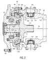
- FIG. 2 shows another set to which the device according to the invention. It is a bearing support for a wheel vehicle manager.
- this assembly includes a stirrup 140 having an annular base 142, which can be fixed to the chassis of a vehicle and to from which depart two ears 144 directed axially. On the outer periphery of these ears are provided with recesses 146 in which are engaged diametrically opposite pivots 148. A piece of revolution 111 is linked to the ears 144 by means of these pivots 146, so that the part 111 can rotate with respect to the part 140 around a pivot axis 150 perpendicular to the axis of rotation 114.
- the part of revolution 111 is fixed by screws 119 to another part of revolution 110. These screws 119 make parts 110 and 111 integral with so that the assembly constituted by parts 110 and 111 forms a casing which constitutes the "first element" of the whole, in relation to which can rotate a shaft 112 around the axis of rotation 114, this shaft 112 being arranged inside this casing.
- the free end of the tree 112 which extends under the part 111 is provided with grooves 112A which allow its connection, via a gimbal, with a drive shaft.
- a flange 113 which protrudes beyond the part 110 is connected to the part 112 by splines 113B and 112B, the splines 113B being formed on the internal periphery of a sleeve 113 'which is integral with the part 113 and which extends inside the housing part 110.
- the flange 113 is integral in rotation with the shaft 112.
- the assembly constituted by the shaft 112 and by the flange 113 therefore constitutes the "second element" which is likely to rotate around axis 114 with respect to the first element consisting of the housing parts 110 and 111.
- the flange 113 has holes in which can be engaged screws or studs 152 which allow the fixing of a wheel.
- the shaft 112 and the flange 113 can be driven in rotation around the axis 114 by a motor shaft, while, thanks to the pivots 148, the assembly 110, 111, 112, 113 can rotate around the axis 150.
- the wheel fixed to the flange 113 is both driving and steering.
- a nut 154 and a pin 156 complete the blocking of the flange 113 relative to the shaft 112.
- the first element consisting of parts 110 and 111, is fixed opposite of rotation around axis 114, and this is the second element constituted by the shaft 112 and the flange 113 which rotates around this axis.
- This second element is supported relative to the first (relative to the workpiece 110) by rolling means 115 and 117 comprising for example tapered bearings.
- the brake device comprises a first series of dog teeth 116 integral with the radial face 118A of the brake piston 118 and a second series of teeth 120 secured to a radial face of a flange 112 ′, integral with the shaft 112 or fixed on the latter, for example by grooves, which is arranged inside the part 111.
- the piston 118 is constantly returned to its active position from braking by helical springs 122 regularly distributed over a circumference.
- the coupling face 118B of the piston is formed on a axial part of this piston close to its radial face 118A.
- the face of coupling 111B of the "first element" is formed on an axial section of the internal periphery of the part 111 which is situated opposite the face 118B.
- the radial end of this axial section forms, with respect to the periphery internal of part 110, a step 111E opposite which extends a recess 118E formed on the piston.
- the coupling faces 111B and 118B have corrugations similar to those of the coupling faces 10B and 18B of Figure 1.
- the part 110 and the piston 118 have also axial cylindrical sealing faces, 110D and 118D, arranged like the faces 10D and 18D of FIG. 1.
- the coupling faces 111B and 118B on the one hand, and the faces sealing 110D and 118D on the other hand, are sealed by seals similar to the seals 30 and 32 of Figure 1, these seals being arranged in grooves similar to grooves 28 and 34.
- the sealing faces are located on a diameter greater than that on which the larger parts are located diameter of the coupling faces 111B and 118B.
- the brake release chamber 126 is provided between the recesses 111E and 118E.
- the conduit of brake release 136 opens into this room, it is arranged in the room 111 (it is only partially shown in Figure 2).
- FIG. 3 shows another set on which can be adapted a device according to the invention.
- This set is formed by a reduction gear whose shaft 212, which for this purpose includes splines 212A, can be rotated by a motor shaft itself driven for example by a hydraulic motor.
- This tree 212 rotates around the axis of rotation 214 on which it is centered.
- the tree has, in a central region, a toothing 260 forming the pinion solar reducer.
- the assembly also includes a planet carrier 262 having cylindrical extensions 264 (for example three in number) which, by means of bearings 266, carry satellites 268 forming gears whose teeth mesh with the teeth of the sun gear 260.
- the planet carrier is fixed with respect to the rotation about the axis 214.
- locking rings 270 and 272 are fixed relative to the planet carrier, the bearings which support the satellites being held between the radial faces opposite these rings.
- the shaft 212 is rotatably supported relative to the ring 272 by rolling means 215.
- the assembly also includes a housing comprising two parts 210 and 211 assembled by screws 213, as well as a third part 211 ', fixed on the part 210 by screws 213 ′, generally having the shape of a flange radial and closing the casing on the side opposite the end of the shaft 212 which carries the 212A splines.
- the internal periphery of part 211 of the casing has teeth internal 274 on which the teeth of the satellites 268 mesh.
- the diameter on which is placed the teeth 274 being obviously much higher to the diameter on which the toothing 260 is placed, the casing formed by all the parts 210, 211 and 211 ′ rotate more slowly than the shaft 212.
- the "first element” is constituted by the casing 210, 211, 211 'which rotates around the axis of rotation 214, while the “second element” includes shaft 212 which also revolves around the axis 214, but at a higher speed. So, because of this difference in speed, the first and second elements are mounted in relative rotation around axis 214.
- Part 211 of the housing is supported in rotation relative to the planet carrier by rolling means 217 and 217 ′, the rolling members of the rolling means 217 'being arranged between the ring 272 and the periphery of the housing part 211.
- the "first element” and the “second element” are supported relative to each other by the means bearing 215, 217 and 217 '.
- the brake device of the assembly shown in Figure 3 includes a first series of teeth 216 secured to a radial face 218A of piston 218, as well as a second series of teeth 220 produced on a radial face of a radial flange 223 which is fixed to the shaft 212 by being made integral in rotation with respect to the latter by splines 212B and 223B. Note that the flange 223 could also be made monobloc with this tree.
- the piston 218 is constantly reminded towards its active braking position by helical springs 222 regularly distributed over a circumference.
- the piston cooperates with part 210 of the casing. More specifically, the 218B coupling face of the piston is located on an axial portion of this piston, on its radially outermost face. In other words, this coupling face delimits the external envelope of the piston.
- the coupling face 210B of the first element is located on an axial face of the inner periphery of the housing part 210 which is located opposite the face 218B of the piston.
- the coupling face 218B is connected by a recess 218E to an axial sealing face 218D of this piston, which is located radially closer to the axis than the face 218B.
- the face of 210B coupling is connected by a 210E recess to the axial face sealing of this first element.
- the axial sealing faces 210D and 218D can be cylindrical with a circular base.
- the bedroom brake release 226 is provided between the recesses forming the faces radial 210E and 218E.
- This brake release chamber can be supplied with fluid to urge the piston to its inactive position through a brake release 236.
- This conduit in fact comprises several sections, namely a axial section 236 which is formed in the part 210 and which opens out directly in the offset face 210E.
- This axial section 236 is connected by a radial section 236A to a groove 236B which is formed on the outer periphery of the shaft 212, this groove being itself connected to a radial section of conduit 236C made in the shaft 212.
- the first axial section 236 and the radial section 236A are blocked by plugs 237 on the side of their ends opposite to, respectively, the brake release chamber 226 and the throat 236B.
- the conduit 236C is itself connected to an axial section 236D made in the shaft, to which another radial section 236E is connected which opens into a new groove 236F produced on the periphery external of shaft 212, between an axial surface of this shaft and a surface axial opposite the planet carrier 262.
- This groove 236F is connected to a duct 236G substantially radial (in the figure, it is oblique), this duct is finally connected to an axial section 236H whose opening, which allows the connection to a brake release source, is located on the radial face 262 ' of the planet carrier which is opposite the casing cover 211 '.
- the section axial 236D is closed by a plug on the free end of the shaft 212 provided with splines 212A, just as the section 236G is closed by a plug at its end opposite the groove 236F.
Landscapes
- Engineering & Computer Science (AREA)
- General Engineering & Computer Science (AREA)
- Mechanical Engineering (AREA)
- Chemical & Material Sciences (AREA)
- Combustion & Propulsion (AREA)
- Transportation (AREA)
- Physics & Mathematics (AREA)
- Electromagnetism (AREA)
- Hydraulic Motors (AREA)
- Braking Arrangements (AREA)
Abstract
Description
- les figures 1 à 3 montrent, en coupe axiale, trois ensembles comprenant un dispositif selon l'invention selon trois variantes, et
- la figure 4 est une vue en coupe transversale selon la ligne IV-IV de la figure 1, montrant seulement le piston de freinage.
Claims (10)
- Dispositif de frein de la rotation d'un premier élément (10 ; 110, 111; 210, 211, 211') par rapport à un deuxième élément (12 ; 112, 113 ; 212, 223), susceptibles de tourner l'un par rapport à l'autre autour d'un axe de rotation (14 ; 114 ; 214) et supportés l'un par rapport à l'autre par l'intermédiaire de moyens de roulement (15 ; 115, 117 ; 215, 217, 217'), le dispositif comprenant des premiers et des deuxièmes moyens de freinage (16, 20 ; 116, 120 ; 216, 220) respectivement solidaires du premier et du deuxième élément vis-à-vis de la rotation autour de l'axe de rotation, ainsi qu'un piston de freinage (18 ; 118 ; 218) apte à occuper une position active de frein dans laquelle il sollicite les premiers et les deuxièmes moyens de freinage en engagement mutuel pour empêcher leur rotation relative et une position inactive dans laquelle lesdits éléments sont libres de tourner l'un par rapport à l'autre, ledit piston étant sollicité en permanence vers sa position active par des moyens de rappel élastique (22 ; 122 ; 222), tandis que le piston est susceptible d'être déplacé vers sa position inactive par alimentation en fluide d'une chambre de défreinage,
caractérisé en ce que les premiers et deuxièmes moyens de freinage sont respectivement constitués par une première (16 ; 116 ; 216) et une deuxième (20 ; 120 ; 220) série de dents appartenant à un crabot, en ce que les dents de la première série sont solidaires d'une face radiale (18A ; 118A ; 218A) du piston (18 ; 118 ; 218), et en ce que le premier élément (10 ; 111 ; 210) et le piston (18 ; 118 ; 218) présentent chacun un profil de couplage s'étendant sur une face axiale de couplage (10B, 18B ; 111B, 118B ; 210B, 218B), lesdits profils de couplage formant, vus en coupe transversale à l'axe de rotation, des ondulations (17) exemptes d'arêtes vives, les ondulations du profil de couplage du premier élément (10 ; 110, 111 ; 210, 211, 211') et les ondulations du profil de couplage du piston (18 ; 116 ; 218) étant aptes à s'imbriquer les unes dans les autres pour rendre le piston solidaire en rotation du premier élément. - Dispositif selon la revendication 1, caractérisé en ce que l'une (18B ; 118B ; 218B) des faces de couplage présente au moins une gorge d'étanchéité (28) apte à recevoir un joint d'étanchéité (30) destiné à réaliser une liaison étanche entre les deux faces axiales de couplage (10B, 18B ; 111B, 118B; 210B, 218B).
- Dispositif selon la revendication 2, caractérisé en ce que la gorge d'étanchéité (28) a une profondeur (P), mesurée pour chaque point de ladite gorge perpendiculairement à une droite tangente (T) au profil de couplage de la face dans laquelle cette gorge est ménagée, qui est sensiblement constante sur le pourtour de la gorge de sorte que, les deux profils de couplage (10B, 18B ; 111B, 118B ; 210B, 218B) ayant des formes complémentaires, la gorge d'étanchéité (28) est apte à loger un joint d'étanchéité (30) de section constante.
- Dispositif selon la revendication 3, caractérisé en ce que la gorge d'étanchéité (28) est apte à contenir un joint (30) de section sensiblement circulaire.
- Dispositif selon l'une quelconque des revendications 2 à 4, caractérisé en ce que le premier élément (10 ; 110, 111 ; 210, 211, 211') et le piston (18 ; 118 ; 218) présentent, chacun, une face axiale d'étanchéité (10D, 18D ; 110D, 118D; 210D, 218D) raccordée par un décrochement (10E, 18E ; 111E, 118E ; 210E, 218E) à la face de couplage (10B ; 111B ; 210B) du premier élément, respectivement à la face de couplage (18B ; 118B ; 218B) du piston, lesdites faces axiales d'étanchéité du premier élément et du piston étant situées en regard l'une de l'autre et coopérant entre elles par l'intermédiaire d'une liaison étanche (32, 34) et en ce que la chambre de défreinage (26 ; 126 ; 226) est ménagée entre la liaison étanche des faces de couplage et la liaison étanche des faces d'étanchéité.
- Dispositif selon la revendication 5, caractérisé en ce que les faces axiales d'étanchéité (10D, 18D ; 110D, 118D ; 210D, 218D) sont cylindriques à base circulaire.
- Dispositif selon l'une quelconque des revendications 1 à 6, caractérisé en ce que le premier élément (10 ; 110, 111 ; 210, 211) s'étend au moins en partie autour du piston (18 ; 118 ; 218) et en ce que la face de couplage (10B ; 111B ; 210B) du premier élément et la face de couplage (18B ; 118B ; 218B) du piston sont respectivement situées sur une face axiale du premier élément qui est tournée vers l'axe de rotation (14 ; 114 ; 214) et sur une face axiale du piston qui tournée à l'opposé de l'axe de rotation.
- Dispositif selon la revendication 7, caractérisé en ce que le premier élément (10 ; 110, 111, 210, 211) est disposé autour du deuxième élément (12 ; 112 ; 212, 223) et en ce que les faces de couplage dudit premier élément et du piston sont situées dans des régions éloignées de l'axe de rotation (14; 114 ; 214).
- Dispositif selon la revendications 7 ou 8, caractérisé en ce que la face de couplage (218B) du piston (218) délimite l'enveloppe externe du piston.
- Dispositif selon la revendication 7 ou 8, caractérisé en ce qu'il existe une face axiale (18D ; 118D) du piston (18 ; 118) qui est davantage éloignée de l'axe (14 ; 114) que la face de couplage (18B ; 118B) de ce piston.
Applications Claiming Priority (5)
| Application Number | Priority Date | Filing Date | Title |
|---|---|---|---|
| FR9708578 | 1997-07-07 | ||
| FR9708578A FR2765637B1 (fr) | 1997-07-07 | 1997-07-07 | Moteur hydraulique ayant le frein situe entre le bloc-cylindres et la came |
| FR9808209A FR2780450B1 (fr) | 1998-06-29 | 1998-06-29 | Moteur hydraulique compact |
| FR9808209 | 1998-06-29 | ||
| PCT/FR1998/001436 WO1999002855A1 (fr) | 1997-07-07 | 1998-07-06 | Dispositif de frein de la rotation relative de deux elements |
Publications (2)
| Publication Number | Publication Date |
|---|---|
| EP0995034A1 EP0995034A1 (fr) | 2000-04-26 |
| EP0995034B1 true EP0995034B1 (fr) | 2002-01-30 |
Family
ID=26233659
Family Applications (2)
| Application Number | Title | Priority Date | Filing Date |
|---|---|---|---|
| EP98935100A Expired - Lifetime EP0995033B1 (fr) | 1997-07-07 | 1998-07-06 | Moteur hydraulique a frein compact |
| EP98936451A Expired - Lifetime EP0995034B1 (fr) | 1997-07-07 | 1998-07-06 | Dispositif de frein de la rotation relative de deux elements |
Family Applications Before (1)
| Application Number | Title | Priority Date | Filing Date |
|---|---|---|---|
| EP98935100A Expired - Lifetime EP0995033B1 (fr) | 1997-07-07 | 1998-07-06 | Moteur hydraulique a frein compact |
Country Status (6)
| Country | Link |
|---|---|
| US (1) | US6293100B1 (fr) |
| EP (2) | EP0995033B1 (fr) |
| JP (1) | JP4101306B2 (fr) |
| CN (1) | CN1097160C (fr) |
| DE (2) | DE69803673T2 (fr) |
| WO (2) | WO1999002855A1 (fr) |
Cited By (3)
| Publication number | Priority date | Publication date | Assignee | Title |
|---|---|---|---|---|
| WO2011069873A3 (fr) * | 2009-12-07 | 2011-09-22 | Schaeffler Technologies Gmbh & Co. Kg | Unité d'entraînement de moyeu de roue |
| DE102011119294A1 (de) | 2011-11-24 | 2013-05-29 | Robert Bosch Gmbh | Bremse für eine Maschine, insbesondere für einen Hydromotor |
| DE102018216573A1 (de) * | 2018-09-27 | 2020-04-02 | Robert Bosch Gmbh | Sicherheitsbremsvorrichtung |
Families Citing this family (19)
| Publication number | Priority date | Publication date | Assignee | Title |
|---|---|---|---|---|
| DE102006058076A1 (de) * | 2006-12-07 | 2008-06-19 | Zf Friedrichshafen Ag | Hydraulischer Radialkolbenmotor |
| FR2926854B1 (fr) * | 2008-01-29 | 2010-03-26 | Poclain Hydraulics Ind | Dispositif de moteur hydraulique pour l'assistance a la transmission mecanique d'un vehicule. |
| WO2010052743A1 (fr) * | 2008-11-10 | 2010-05-14 | S.A.I. Società Apparecchiature Idrauliche S.p.A. | Moteur hydraulique à cylindres radiaux pourvu d’un système de détection de la vitesse de rotation |
| FR2940672B1 (fr) * | 2008-12-31 | 2011-01-21 | Poclain Hydraulics Ind | Moteur hydraulique a pistons radiaux et commande par cylindre |
| CN102858578B (zh) * | 2010-04-30 | 2016-08-17 | 马格纳斯泰尔汽车技术两合公司 | 传动系 |
| US8534431B2 (en) | 2010-07-21 | 2013-09-17 | Warn Industries, Inc. | Face tooth hydraulic piston brake |
| DE102012015012B4 (de) | 2011-08-06 | 2024-02-15 | Neumayer Tekfor Engineering Gmbh | Parksperre |
| KR101350179B1 (ko) * | 2011-10-28 | 2014-01-10 | 주식회사 제이케이 | 지반 다짐용 콤팩터 |
| CN104246214B (zh) * | 2012-04-28 | 2017-07-11 | 罗伯特·博世有限公司 | 具有制动器的径向柱塞马达 |
| CN103825397A (zh) * | 2014-03-04 | 2014-05-28 | 黄坤祥 | 新型动力源 |
| FR3026791B1 (fr) * | 2014-10-03 | 2019-04-19 | Poclain Hydraulics Industrie | Mecanisme hydraulique muni de moyens de guidage en translation des pistons |
| DE102015222291B4 (de) * | 2015-11-12 | 2019-09-12 | Robert Bosch Gmbh | Radialkolbenmaschine mit verdrehgesicherten Bremsmitteln |
| EP3339236B1 (fr) * | 2016-12-21 | 2020-06-17 | Otis Elevator Company | Engrenage à freinage automatique et dispositif de transport de personnes comprenant un engrenage à freinage automatique |
| CN108412684B (zh) * | 2018-03-07 | 2019-06-21 | 大连理工大学 | 一种三相交流液压马达 |
| FR3097017B1 (fr) * | 2019-06-04 | 2021-07-30 | Poclain Hydraulics Ind | Machine hydraulique comprenant un dispositif de freinage statique intégré |
| WO2021008853A1 (fr) | 2019-07-17 | 2021-01-21 | Nv Bekaert Sa | Câble en acier destiné au renforcement de caoutchouc |
| FR3137724B1 (fr) * | 2022-07-08 | 2025-06-27 | Poclain Hydraulics Ind | Machine hydraulique comprenant un frein à crabot |
| FR3155468A1 (fr) * | 2023-11-20 | 2025-05-23 | Robert Bosch Gmbh | Machine hydrostatique de rotation à frein optimisé |
| WO2025228503A1 (fr) * | 2024-04-29 | 2025-11-06 | Danfoss A/S | Système de frein de stationnement pour unité de piston radial hydrostatique |
Family Cites Families (8)
| Publication number | Priority date | Publication date | Assignee | Title |
|---|---|---|---|---|
| DE1949973C3 (de) | 1969-10-03 | 1980-10-30 | Robert Bosch Gmbh, 7000 Stuttgart | Hydrostatisches Aggregat |
| DE2508771C2 (de) * | 1975-02-28 | 1982-11-25 | Wabco Fahrzeugbremsen Gmbh, 3000 Hannover | Selbsttätige Nachstellvorrichtung für Scheibenbremsen |
| DE3343596A1 (de) * | 1983-12-02 | 1985-06-13 | Dr.Ing.H.C. F. Porsche Ag, 7000 Stuttgart | Antriebssystem fuer einen dreh-, schwenk- und fahrantrieb eines fahrzeugs |
| DE3619948C2 (de) * | 1986-06-13 | 1995-05-18 | Knorr Bremse Ag | Kombinierter Betriebs- und Federspeicherbremszylinder |
| DE58905584D1 (de) | 1988-03-26 | 1993-10-21 | Fortuna Werke Maschf Ag | Verfahren zum Schleifen eines Polygon-Kegels auf einer numerisch gesteuerten Schleifmaschine. |
| FR2644210B1 (fr) * | 1989-03-07 | 1994-06-03 | Poclain Hydraulics Sa | Dispositif d'immobilisation mutuelle de deux elements montes a rotation relative |
| FR2739418B1 (fr) | 1995-10-02 | 1997-12-19 | Poclain Hydraulics Sa | Moteur hydraulique d'assistance |
| DE19637570A1 (de) * | 1996-09-14 | 1998-03-19 | Zahnradfabrik Friedrichshafen | Hydrostatisch-mechanischer Radantrieb |
-
1998
- 1998-07-06 EP EP98935100A patent/EP0995033B1/fr not_active Expired - Lifetime
- 1998-07-06 JP JP50823999A patent/JP4101306B2/ja not_active Expired - Fee Related
- 1998-07-06 US US09/462,050 patent/US6293100B1/en not_active Expired - Lifetime
- 1998-07-06 WO PCT/FR1998/001436 patent/WO1999002855A1/fr not_active Ceased
- 1998-07-06 DE DE69803673T patent/DE69803673T2/de not_active Expired - Lifetime
- 1998-07-06 EP EP98936451A patent/EP0995034B1/fr not_active Expired - Lifetime
- 1998-07-06 DE DE69803674T patent/DE69803674T2/de not_active Expired - Lifetime
- 1998-07-06 CN CN98806754A patent/CN1097160C/zh not_active Expired - Fee Related
- 1998-07-06 WO PCT/FR1998/001435 patent/WO1999002854A1/fr not_active Ceased
Cited By (5)
| Publication number | Priority date | Publication date | Assignee | Title |
|---|---|---|---|---|
| WO2011069873A3 (fr) * | 2009-12-07 | 2011-09-22 | Schaeffler Technologies Gmbh & Co. Kg | Unité d'entraînement de moyeu de roue |
| EP2927529A1 (fr) * | 2009-12-07 | 2015-10-07 | Schaeffler Technologies GmbH & Co. KG | Unité d'entraînement de moyeu à roue |
| DE102011119294A1 (de) | 2011-11-24 | 2013-05-29 | Robert Bosch Gmbh | Bremse für eine Maschine, insbesondere für einen Hydromotor |
| DE102018216573A1 (de) * | 2018-09-27 | 2020-04-02 | Robert Bosch Gmbh | Sicherheitsbremsvorrichtung |
| US11673218B2 (en) | 2018-09-27 | 2023-06-13 | Robert Bosch Gmbh | Safety braking device |
Also Published As
| Publication number | Publication date |
|---|---|
| US6293100B1 (en) | 2001-09-25 |
| DE69803674T2 (de) | 2005-09-08 |
| JP2002510374A (ja) | 2002-04-02 |
| EP0995033A1 (fr) | 2000-04-26 |
| EP0995034A1 (fr) | 2000-04-26 |
| DE69803673T2 (de) | 2002-09-12 |
| DE69803673D1 (de) | 2002-03-14 |
| WO1999002855A1 (fr) | 1999-01-21 |
| CN1261945A (zh) | 2000-08-02 |
| JP4101306B2 (ja) | 2008-06-18 |
| DE69803674D1 (de) | 2002-03-14 |
| CN1097160C (zh) | 2002-12-25 |
| EP0995033B1 (fr) | 2002-01-30 |
| WO1999002854A1 (fr) | 1999-01-21 |
Similar Documents
| Publication | Publication Date | Title |
|---|---|---|
| EP0995034A1 (fr) | Dispositif de frein de la rotation relative de deux elements | |
| EP2689110A1 (fr) | Dispositif d'obturation a verrouillage auto-activable | |
| FR2517003A1 (fr) | Moyeu de roue a reducteur et frein integre | |
| FR2796886A1 (fr) | Dispositif de palier de support d'une roue equipe de moyens de freinage | |
| EP0148794A2 (fr) | Dispositif pour régler la position angulaire d'un élément menant, accouplé à un autre élément mené susceptibles d'être entraînés en rotation | |
| EP0969205B1 (fr) | Moteur hydraulique compact | |
| CA1230296A (fr) | Moyeu de roue a frein integre | |
| EP4455518A1 (fr) | Dispositif d'actionnement pour système de transmission | |
| WO1997042433A1 (fr) | Appareil d'accouplement hydrocinetique a piece d'entrainement de languettes, notamment pour vehicule automobile | |
| FR2535254A1 (fr) | Moyeu de roue a frein integre | |
| EP0522983A1 (fr) | Moyeu à roue libre pour cycles | |
| FR2782767A1 (fr) | Differentiel a blocage,sensible au couple et comportant peu de pieces | |
| EP3379105B1 (fr) | Élément d'engrenage à rouleaux | |
| FR2761431A1 (fr) | Dispositif de freinage | |
| WO2016174322A1 (fr) | Piece excentrique pour systeme de variation du taux de compression d'un moteur thermique | |
| FR2990254A1 (fr) | Systeme d'entrainement en rotation d'une roue de vehicule automobile | |
| EP0904498B1 (fr) | Dispositif d'irreversibilite a roues a rochet et disque de frottement pour systeme d'entrainement du type vis-ecrou | |
| FR2926247A1 (fr) | Moyeu de roue arriere de bicyclette | |
| FR3167677A1 (fr) | Système d’accouplement d’arbres de transmission et procédé de commande d’un tel système d’accouplement d’arbres de transmission | |
| FR2765637A1 (fr) | Moteur hydraulique ayant le frein situe entre le bloc-cylindres et la came | |
| FR3167678A1 (fr) | Système d’accouplement d’arbres de transmission | |
| FR2780758A1 (fr) | Accouplement visqueux a verrouillage comportant un double canal de cisaillement | |
| FR2745234A1 (fr) | Accouplement en rotation d'une bride de roue a un organe de sortie d'un joint d'articulation d'une transmission | |
| FR3140413A1 (fr) | Boîte de vitesses d’un véhicule automobile | |
| FR3167679A1 (fr) | Système d’accouplement d’arbres de transmission |
Legal Events
| Date | Code | Title | Description |
|---|---|---|---|
| PUAI | Public reference made under article 153(3) epc to a published international application that has entered the european phase |
Free format text: ORIGINAL CODE: 0009012 |
|
| 17P | Request for examination filed |
Effective date: 20000110 |
|
| AK | Designated contracting states |
Kind code of ref document: A1 Designated state(s): DE FR GB |
|
| GRAG | Despatch of communication of intention to grant |
Free format text: ORIGINAL CODE: EPIDOS AGRA |
|
| 17Q | First examination report despatched |
Effective date: 20010528 |
|
| GRAG | Despatch of communication of intention to grant |
Free format text: ORIGINAL CODE: EPIDOS AGRA |
|
| GRAH | Despatch of communication of intention to grant a patent |
Free format text: ORIGINAL CODE: EPIDOS IGRA |
|
| GRAH | Despatch of communication of intention to grant a patent |
Free format text: ORIGINAL CODE: EPIDOS IGRA |
|
| GRAA | (expected) grant |
Free format text: ORIGINAL CODE: 0009210 |
|
| REG | Reference to a national code |
Ref country code: GB Ref legal event code: IF02 |
|
| AK | Designated contracting states |
Kind code of ref document: B1 Designated state(s): DE FR GB |
|
| REF | Corresponds to: |
Ref document number: 69803674 Country of ref document: DE Date of ref document: 20020314 |
|
| GBT | Gb: translation of ep patent filed (gb section 77(6)(a)/1977) |
Effective date: 20020422 |
|
| PLBE | No opposition filed within time limit |
Free format text: ORIGINAL CODE: 0009261 |
|
| STAA | Information on the status of an ep patent application or granted ep patent |
Free format text: STATUS: NO OPPOSITION FILED WITHIN TIME LIMIT |
|
| 26N | No opposition filed | ||
| PGFP | Annual fee paid to national office [announced via postgrant information from national office to epo] |
Ref country code: GB Payment date: 20080711 Year of fee payment: 11 |
|
| GBPC | Gb: european patent ceased through non-payment of renewal fee |
Effective date: 20090706 |
|
| PG25 | Lapsed in a contracting state [announced via postgrant information from national office to epo] |
Ref country code: GB Free format text: LAPSE BECAUSE OF NON-PAYMENT OF DUE FEES Effective date: 20090706 |
|
| PGFP | Annual fee paid to national office [announced via postgrant information from national office to epo] |
Ref country code: DE Payment date: 20150713 Year of fee payment: 18 |
|
| REG | Reference to a national code |
Ref country code: FR Ref legal event code: PLFP Year of fee payment: 19 |
|
| REG | Reference to a national code |
Ref country code: DE Ref legal event code: R119 Ref document number: 69803674 Country of ref document: DE |
|
| PG25 | Lapsed in a contracting state [announced via postgrant information from national office to epo] |
Ref country code: DE Free format text: LAPSE BECAUSE OF NON-PAYMENT OF DUE FEES Effective date: 20170201 |
|
| REG | Reference to a national code |
Ref country code: FR Ref legal event code: PLFP Year of fee payment: 20 |
|
| PGFP | Annual fee paid to national office [announced via postgrant information from national office to epo] |
Ref country code: FR Payment date: 20170724 Year of fee payment: 20 |