EP0994263A1 - Antidiebstahlvorrichtung für ein Kraftfahrzeugrad - Google Patents
Antidiebstahlvorrichtung für ein Kraftfahrzeugrad Download PDFInfo
- Publication number
- EP0994263A1 EP0994263A1 EP99402407A EP99402407A EP0994263A1 EP 0994263 A1 EP0994263 A1 EP 0994263A1 EP 99402407 A EP99402407 A EP 99402407A EP 99402407 A EP99402407 A EP 99402407A EP 0994263 A1 EP0994263 A1 EP 0994263A1
- Authority
- EP
- European Patent Office
- Prior art keywords
- cap
- shape memory
- locking
- internal
- ring
- Prior art date
- Legal status (The legal status is an assumption and is not a legal conclusion. Google has not performed a legal analysis and makes no representation as to the accuracy of the status listed.)
- Granted
Links
- 238000010438 heat treatment Methods 0.000 claims description 30
- 210000000056 organ Anatomy 0.000 claims description 20
- 229910001000 nickel titanium Inorganic materials 0.000 claims description 7
- 229910000842 Zamak Inorganic materials 0.000 claims description 6
- HZEWFHLRYVTOIW-UHFFFAOYSA-N [Ti].[Ni] Chemical compound [Ti].[Ni] HZEWFHLRYVTOIW-UHFFFAOYSA-N 0.000 claims description 5
- 229910045601 alloy Inorganic materials 0.000 claims description 5
- 239000000956 alloy Substances 0.000 claims description 5
- 230000009471 action Effects 0.000 claims description 4
- 239000012777 electrically insulating material Substances 0.000 claims description 4
- 238000001816 cooling Methods 0.000 claims description 2
- 239000000463 material Substances 0.000 description 3
- 230000008901 benefit Effects 0.000 description 2
- 238000000605 extraction Methods 0.000 description 2
- 238000000034 method Methods 0.000 description 2
- 229910000967 As alloy Inorganic materials 0.000 description 1
- 229910052782 aluminium Inorganic materials 0.000 description 1
- 230000008859 change Effects 0.000 description 1
- 230000006870 function Effects 0.000 description 1
- 238000009434 installation Methods 0.000 description 1
- 239000011810 insulating material Substances 0.000 description 1
- 238000012423 maintenance Methods 0.000 description 1
- 238000004519 manufacturing process Methods 0.000 description 1
- 230000000149 penetrating effect Effects 0.000 description 1
- 230000009467 reduction Effects 0.000 description 1
- 230000000284 resting effect Effects 0.000 description 1
Images

Classifications
-
- B—PERFORMING OPERATIONS; TRANSPORTING
- B60—VEHICLES IN GENERAL
- B60B—VEHICLE WHEELS; CASTORS; AXLES FOR WHEELS OR CASTORS; INCREASING WHEEL ADHESION
- B60B3/00—Disc wheels, i.e. wheels with load-supporting disc body
- B60B3/14—Attaching disc body to hub ; Wheel adapters
- B60B3/16—Attaching disc body to hub ; Wheel adapters by bolts or the like
- B60B3/165—Attaching disc body to hub ; Wheel adapters by bolts or the like with locking devices for the fixing means, e.g. screw or nut covers
-
- F—MECHANICAL ENGINEERING; LIGHTING; HEATING; WEAPONS; BLASTING
- F16—ENGINEERING ELEMENTS AND UNITS; GENERAL MEASURES FOR PRODUCING AND MAINTAINING EFFECTIVE FUNCTIONING OF MACHINES OR INSTALLATIONS; THERMAL INSULATION IN GENERAL
- F16B—DEVICES FOR FASTENING OR SECURING CONSTRUCTIONAL ELEMENTS OR MACHINE PARTS TOGETHER, e.g. NAILS, BOLTS, CIRCLIPS, CLAMPS, CLIPS OR WEDGES; JOINTS OR JOINTING
- F16B41/00—Measures against loss of bolts, nuts, or pins; Measures against unauthorised operation of bolts, nuts or pins
- F16B41/005—Measures against unauthorised operation of bolts, nuts or pins
-
- E—FIXED CONSTRUCTIONS
- E05—LOCKS; KEYS; WINDOW OR DOOR FITTINGS; SAFES
- E05B—LOCKS; ACCESSORIES THEREFOR; HANDCUFFS
- E05B51/00—Operating or controlling locks or other fastening devices by other non-mechanical means
- E05B51/005—Operating or controlling locks or other fastening devices by other non-mechanical means by a bimetallic or memory-shape element
Definitions
- the present invention relates to a protection device anti-theft device for a motor vehicle wheel.
- this known device has the major drawback of require shape fixing screw heads particular, thereby increasing manufacturing costs, and the risk of losing the cap specially adapted to the head screws for tightening or loosening, thus preventing the user to change his wheel especially in case of puncture.
- the object of the present invention is to eliminate the disadvantages above by proposing a device for anti-theft protection for a vehicle wheel mounted on the wheel hub by means of at least one threaded element of removable fixing which can be operated by a tool and which is characterized in that it constitutes an obstacle, selectively removable, at the access of the fixing element by the tool, this obstacle being immobilized in the position of use by at least one heat-sensitive memory member allowing, by heating to a minimum temperature determined to unlock the obstacle.
- the obstacle comprises a cap covering the threaded fixing element and made up an external part and an internal part which can pivot in a limited way in the external part around an axis longitudinal pivot between a position of locking of the cap to the threaded fixing element under the action of a first couple of forces exerted on the part internal by two return springs arranged symmetrically to the pivot axis to prevent axial withdrawal of the cap of the threaded fixing element and a position unlocking under the action of a second pair of forces opposite and greater than the first couple of forces, exerted by two symmetrical thermosensitive shape memory members to the pivot axis and heated to the minimum temperature determined to allow axial removal of the cap of the threaded fixing element.
- the two heat-sensitive shape memory organs are mounted on the internal part of the cap and consist of each by a curved blade of alloy preferably nickel-titanium.
- the two return springs are also mounted on the internal part of the cap and each consist of a hairpin spring with two arms in support prestressed respectively on a stop wall radially internal to the internal part of the cap and a radially internal abutment wall of the external part of this one and the turn of connection of the two branches is assembled around an axis of the internal part parallel to the axis of pivoting thereof so as to resiliently recall the internal part towards a stop wall of the external part and restore the initial shape of each memory organ of form after cooling thereof.
- Each shape memory blade has one end held between two radially internal parallel walls of the outer part of the cap and its other end located between the abutment wall of the external part on which bears the internal part in the position of locking and the abutment wall of the internal part on which bears the corresponding branch of the spring hairpin.
- the locking means of the internal part of the cap to the threaded fixing element include two tabs symmetrical with radially internal locking lugs engaging respectively in two portions of gorges diametrically opposite of the threaded fixing element in locking position, the two locking pins that can slide in the two groove portions during pivoting of the internal part to its position of unlocking at which the lugs are released from groove portions to allow axial withdrawal of the cap.
- the inner and outer parts of the cap are fixed removable from one another by two side tabs diametrically opposed hoses cut in the wall lateral annular side of the outer part of the cap and having protrusions at their lower ends interlock cooperating with the internal part for the lock axially in the outer part of the cap.
- the internal and external parts of the cap are made of nickel-plated zamak.
- a gripping and heating means of the cap is provided to allow removal of the threaded element cap fixing during heating of the two memory organs of forms at the predetermined minimum temperature.
- the obstacle comprises a cap covering the threaded fixing element and fixed removably to the threaded fixing element, in position of use, by at least one locking lever mounted swivel in the cap and can be tilted to a position unlocking under the control of the memory member of heat-sensitive form heated to allow axial withdrawal of the cap of the threaded fixing element.
- Lock lever includes two lever arms bent substantially at right angles respectively a first lever arm substantially parallel to the longitudinal axis the cap in the locked position and having at its free end radially internal locking lug engaging in a conjugate recess of the threaded element a second lever arm perpendicular to the longitudinal axis of the cap in the locked position, the shape memory member being disposed between the second lever arm and the top closing wall of the cap to rotate the first lever arm in its unlocked position when said member is heated to the minimum temperature determined.
- the shape memory organ is in the form of a spring helical arranged coaxially in the cap and extending when heated to minimum temperature determined.
- the lever is returned to the locked position by a convex leaf spring interposed between the second lever arm and side wall of the cap.
- three locking levers are provided extending angularly substantially at 120 ° from each other others around the threaded fastener and the member to shape memory acts simultaneously on the three levers of locking to unlock them when the organ is heated to the minimum temperature determined.
- a gripper and cap heating means is provided to allow removal of the threaded element cap fixing during heating of the shape memory member to the minimum temperature determined.
- the obstacle comprises a cap covering the threaded fixing element and produced in the form of a truncated cone longitudinally split from so as to constitute two symmetrical parts enclosing at level of the small base of the truncated cone the threaded element fastening by being locked to it to prevent the axial withdrawal of the cap and which can be separated elastically from each other by the memory organ of heated form to the minimum temperature determined for unlock the cap of the threaded fixing element.
- the shape memory organ consists of a blade convex with substantially semicircular section arranged standing in the cap on two semicircular plates coplanar interns supported on two respectively transverse semicircular shoulders of the truncated cone so that by heating the shape memory organ to the minimum temperature determined, this exerts on both symmetrical parts of the truncated cone two radial forces opposite pushing aside these two parts to the position of unlocking the cap.
- the two symmetrical parts each include at least a radially internal locking projection in the locked position in a conjugate recess of the threaded fixing element.
- the two semi-circular plates are made in one electrically insulating material and the memory blade of form is housed in the cap while being electrically isolated from it.
- a means for gripping and heating the cap is provided to allow removal of the threaded element cap fixing during heating of the shape memory member to the minimum temperature determined.
- the obstacle comprises a ring housed in a counterbore of the wheel rim coaxially with the threaded fixing element by surrounding adjacent this element and the ring is immobilized axially in the counterbore by the shape memory member in ring housed on the one hand in a radially external groove of the ring and secondly in a circular groove made in the side wall of the rim defining the passage of the threaded fixing element so as to retain axially the ring relative to the rim in position, of use, the shape memory ring retracting by heating to the minimum temperature determined in the throat of the begue to release it axially.
- the shape memory ring is split and has one of its free ends curved substantially at right angles penetrating into an obviously conjugate realized at the bottom of the throat of the obstacle ring so as to contract mechanically, using an appropriate tool, the ring by bringing its ends together for mounting in the circular groove.
- This tool is also designed as a means of gripping and to heat the ring to allow it to be removed and the ring shape memory organ during the heating of this organ to the determined minimum temperature.
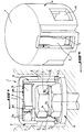
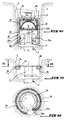
- FIG. 1 represents a perspective view cut away from the anti-theft protection device according to a first mode of realization of the invention.
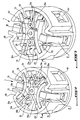
- Figure 2 is a perspective view of the interior of the anti-theft protection device of FIG. 1 in position lock.
- Figure 3 is a perspective view similar to that of FIG. 2 representing the device in the position of unlocking.
- Figure 4 is a perspective view of the external part the anti-theft protection device of figure 1.
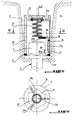
- Figure 5 is a sectional view of a device for anti-theft protection according to a second embodiment of the invention.
- Figure 6 is a sectional view along line VI-VI of Figure 5.
- Figure 7 is a view similar to that of Figure 5 and representing the device in the unlocked position.
- Figure 8 is a sectional view showing a device anti-theft protection according to a third mode of realization of the invention.
- Figure 9 is a sectional view along line IX-IX of Figure 8.
- Figure 10 is a view similar to that of Figure 8 and representing the device in the unlocked position.
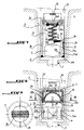
- Figure 11 is a sectional view showing a device anti-theft protection according to a fourth mode of realization of the invention.
- Figure 12 is a sectional view along line XII-XII in Figure 11.
- Figure 13 is a view similar to that of Figure 11 and representing the device in the unlocked position.
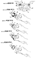
- FIGS. 14A to 14D represent the method for installing the anti-theft protection device of figures 11 to 13.
- FIGS. 15A to 15E represent the method of unlocking the anti-theft device of Figures 11 to 13.
- FIGS 1 to 4 show the first mode of realization of the anti-theft protection device the invention.
- This device comprises a cap generally referenced in 1 removably attached to a screw 2 for fixing the rim 3 from a vehicle wheel to the wheel hub.
- the cap 1 covers the head 4 of the screw 2 by being housed in a well 5 of the rim 3 of so as to constitute an obstacle to the access of the screw head 4 fixing 2 by a tool.
- the cap 1 comprises an external part 6 forming the cap proper, cylindrical in shape closed at its upper end by a circular wall 7 and comprising two flexible diametrically lateral legs opposite 8 cut in the side wall of the part external 6 and comprising at their free ends projections 9 for locking to the external part 6 an internal part 10 of the cap 1 to form an assembly unitary.
- the internal part 10 of the cap 1 is mounted so swivel at a limited swivel angle in the external part 6 around a longitudinal pivot axis 11 secured to the upper wall 7 of the external part 6.
- This internal part 10 comprises means for locking it to the head 4 of the fixing screw 2 and constituted by two diametrically longitudinal legs opposite 12 respectively comprising two lugs of radially internal locking 12a each engaging in a groove portion 14 machined in the head 4 of the screw attachment 2 so as to prevent the axial withdrawal of the cap 1 relative to the fixing screw 2.
- the internal part 10 further comprises on its part upper two springs 13 arranged symmetrically to the axis 11 and making it possible to exert a couple of restoring forces of the internal part 10 at an extreme angular position at which the two legs 12 have their locking lugs 12a engaged respectively in the two portions of grooves 14.
- Each return spring 13 is constituted by a spring hairpin whose two branches 13a are supported prestressed respectively on a stop wall radially internal 10a of the internal part 10 and a wall radially internal abutment 6a of the external part 6 and the turn 13b connecting branches 13a is mounted on an axis 10b of the internal part 10 parallel to the pivot axis 11, so as to resiliently recall the internal part 10 towards a stop wall 6b of the external part 6 as shown in figure 2.
- the internal part 10 also comprises in its part upper two heat-sensitive memory organs 15 arranged symmetrically to the axis 11 and allowing, when heated to a determined minimum temperature, to recover their initial shape and exercise on the inner 10 a torque of opposite and greater force than that exerted by the two return springs 13 to bring the two legs 12 to a released position for unlocking the grooves 14 of the head 4 of the fixing screw 2.
- the two memory members of form 15 each consist of a blade curved in locking position of the internal part 10 to the screw attachment 2 and one of its ends is maintained between two radially internal parallel walls 6a of the external part 6 and the other end is located between the abutment wall 6b of the external part 6 towards which comes in support the internal part 10 in the locked position and the abutment wall 10a of the internal part 10 on which is in support the corresponding branch 13a of the spring in pin 13.
- each shape memory blade is made of an alloy nickel-titanium regaining its shape by simple heating above 80 ° C and the external part 6 of the plug 1 is made of nickel-plated zamak while the internal part 10 of it is made of nickel-plated zamak or berylium-aluminum to obtain foundry parts of precision and offering a good galvanic couple with the shape memory organs 15.
- the user has a gripping tool and heating to heat the two blades to shape memory 15 so that once heated to the determined minimum temperature, they deform cap 1 lock configuration at screw head 4 represented in FIG. 2 in the configuration of unlocking thereof shown in Figure 3.
- a device is not shown but can be easily designed as comprising a heating element which can come directly in contact with the external part 6 of the cap 1 in order to heat the two shape memory members 15 and two flexible blades for extracting the cap 1 in engaging in two cavities in the side wall of the external part 6 such as those referred to in 6c.
- memory slides 15 are kept in the configuration shown in Figure 2 by the two return springs 13 which exert a restoring force, for example around ldaN, allowing maintain the legs 12 of the internal part 10 in locked position at screw head 4, thereby preventing any extraction of the cap 1 in the axial direction.
- the anti-theft protection device described above has many advantages, including a reduction in the height of it above the head of screw, low effort required for shape memory organs (twist lock), the presence of the two branches side 8 of the external part 6 ensuring security of maintenance in the event of heating by braking, a galvanic compatibility between memory devices shape and the nickel-plated zamak material used in particular for the outer part of the cap, extracting the device requires a specific gripping tool, and the part external can be used to cover the screw heads not locked.
- the anti-theft protection device includes a generally cylindrical cap 16 covering coaxially the screw head 4 resting on the base 4a of head 4 via a washer R in one electrically insulating material.
- the cap 16 is housed in the well 5 of wheel 3 so as to prevent access to the screw head 4.
- the device comprises at least one locking lever 17 pivotally mounted in the cap 16 around an axis 18 perpendicular to the longitudinal axis of the cap and worn by a radial support tab 19 integral with the wall side of the cap and can be switched between a position for locking the cap 16 to the screw head 4 and a unlocking position of the cap 16 of this head under the control of a thermosensitive shape memory member housed in the cap 16 coaxially with the axis of the screw fixing 2.
- the locking lever includes two lever arms bent at substantially right angles, respectively a first lever arm 17a substantially parallel to the longitudinal axis of the screw axis fixing 2 in the locking position of the cap 16 and having a locking lug at its free end radially internal 17a1 engaging in a recess conjugate 4b of the screw head 4 and a second lever arm 17b perpendicular to the longitudinal axis of screw 2 or to the longitudinal axis of the cap 16 in the position of locking thereof, the shape memory member 20 being disposed between the second lever arm 17b and the wall upper closure 16a of the cap 16 so as to make pivot by thrust exerted on the lever arm 17b the lever arm 17a in its unlocked position when the shape memory member 20 is heated to a determined minimum temperature, for example 80 ° C when this body is made of nickel-titanium alloy.
- the shape memory member 20 is preferably in the form of coil spring extending when heated to minimum temperature determined.
- the lever arm 17a of the locking lever 17 is returned to the locked position by a spring 21 in shape of a convex blade interposed between the lever arm 17a and the side wall of the cap 16.
- the spring 21 is mounted vertically braced in support of its two ends respectively on the insulating washer R and the support tab 19.
- the device comprises three levers for identical lock 17 extending angularly to 120 ° from each other around the fixing screw 2 and the helical spring constituting the memory member of form 20 with its extreme lower turn supported on the three lever arms 17b of the locking levers 17 of so as to act simultaneously on them when heated to the minimum temperature determined to unlock at the same time time the three levers 17 of the screw head 4.
- each locking lever 17 is made of an electrically insulating material and thermally conductive and the upper extreme turn of the spring constituting the shape memory member 20 is in support on a sleeve 22 of an electrically material insulating and thermally conductive fixed in the wall 16a of the cap 16 coaxially to the longitudinal axis thereof.
- the wall 16a of the cap 16 carries outside of it a part coming from material 16a1 and having a shape allowing an external device 23 to grasp and heat the cap 16 in order to extract it from the screw head 4.
- Figure 7 shows that the gripper and heater 23 schematically comprises a body with two electrodes 24 powered by a power source 25 allowing circulate in the body of the cap 16, preferably in nickel-plated zamak, the heating current of the spring at shape memory 20.
- the shape memory spring 20 When the shape memory spring 20 is at a temperature below the determined minimum temperature, for example 80 ° C, the locking arms 17 occupy their locking positions from the cap 16 to the head of screw 4. When heating using the gripper and heater 23 the shape memory spring 20 to a temperature equal to or higher than this minimum temperature determined, it lengthens to regain its shape and simultaneously switches the three levers 17 to their unlock positions so that the device gripper and heater can extract axially the cap 16.
- the anti-theft protection device includes a cap 26 covering the screw head 4 coaxially with it while being housed in the well 5 of the wheel rim 3 of so as to constitute an obstacle to access by a tool of the screw head 4.
- the cap 26 is produced in the form of a truncated cone with longitudinal slot 27 partially separating the trunk of cone in two symmetrical parts enclosing at the level of the small base of the truncated cone the screw head 4 while being there locked to prevent axial removal of the cap 26 of the screw head 4.
- the cap 26 comprises at lower part two or more locking projections radially internal 26a respectively engaging in two conjugate recesses 4a of the screw head 4.
- the device further comprises a shape memory organ thermosensitive 28, preferably made of an alloy of nickel-titanium, and arranged so that by being heated to a determined minimum temperature, for example 80 ° C, it exerts in the cap 26 two radially opposite forces allowing to separate one from the other the two parts symmetrical lower part of the truncated cone constituting the small base of it to disengage the protrusions from locking 26a of the conjugate recesses 4a of the head of screw 4.
- a shape memory organ thermosensitive 28 preferably made of an alloy of nickel-titanium, and arranged so that by being heated to a determined minimum temperature, for example 80 ° C, it exerts in the cap 26 two radially opposite forces allowing to separate one from the other the two parts symmetrical lower part of the truncated cone constituting the small base of it to disengage the protrusions from locking 26a of the conjugate recesses 4a of the head of screw 4.
- the shape memory member 28 is constituted by a convex blade with a substantially semi-circular section arranged upright in the cap 26 on two semi-circular plates internal coplanar 29 supported respectively on two semi-circular shoulders internal transverse 26b of the truncated cone of the cap 26 of so that by heating the convex blade 28 to the temperature determined minimum, this has its two opposite ends braced to the side wall of the cap 26 deviating each other to also separate from each other the two semicircular plates 29 and the two parts symmetrical lower ends of the cap 26 to release the cap 26 of the screw head 4 as shown in the figure 10.
- the shape memory member 28 is housed in the upper part of the cap 26 while being electrically insulated therefrom by an internal cylindrical sleeve 30 and a circular plate upper 31 made of an electrical insulating material.
- the circular plate 31 has two through holes respectively of two electrodes 32 of a device gripper and heater 33 partially shown and coming into contact directly on the memory organ of form 28 to heat it to the minimum temperature of the cap 26.
- the anti-theft protection device includes a ring 34 housed in a counterbore 35 machined in the well 5 of the wheel rim 3 so that the ring 34 surrounds so adjacent the screw head 4 coaxially to it for constitute an obstacle of access to this screw head by a tool.
- the ring 34 is immobilized axially in the counterbore 35 by a heat-sensitive ring memory member 36 housed on the one hand in a radially external groove 37 of the ring 34 and on the other hand in a circular groove 38 made in the wall of well 5 so as to retain axially the ring 34 relative to the rim 3 in position of use.
- the shape memory ring 36 is split and has one of its free ends 36a curved substantially at right angle and entering a conjugate recess 37a made at the bottom of the groove 37 of the ring 34.
- the part end of the shape memory ring 36 comprising the curved end 36a is curved on the inside of the circle formed by the remaining part of this ring of so as to form a spiral shape allowing, using of an appropriate tool, the introduction of the ring 36 into the circular groove 38 when mounting the obstacle ring 34.
- the ring at shape memory 36 can be made of nickel-titanium alloy allowing it to regain its shape when heated at a temperature at least equal to 80 ° C.
- Figures 14A to 14D show the different phases of installation of the anti-theft protection device in the well 5 of the rim 3 using an appropriate tool 39.
- the tool 39 provided with the assembly constituted by the ring 34 and the shape memory ring 36 is presented in front of the screw fixing 2. This tool is arranged so as to bring each other the two ends of the memory ring 36.
- this assembly is inserted by tool 39 into well 5 and by rotation of the tool 39 in the direction indicated by the arrow at Figure 14C, the shape memory ring 36 is introduced in circular groove 38 with release of the two ends of the ring 36.
- the tool 39 is then removed as shown in Figure 14D.
- Figures 15A to 15E show the use of the tool 39 allowing the heating of the memory ring form 36 and the grip of the assembly constituted by the obstacle ring 34 and this ring.
- Figure 15A shows that tool 39 is shown in front of the fixing screw 2 and is then inserted into the well 5 as shown in FIG. 15B.
- Tool 39 is then rotated as indicated by the arrow in Figure 15C to bring the two ends of the ring together with shape memory 36 then the user presses the key 39a for switching on the heating element contained in the tool 39 for heating the ring 36 which is contracts from the minimum temperature determined for that the axial withdrawal of the assembly constituted by the ring 34 and the ring 36 can be made as shown in figure 15E.
- the anti-theft protection device as described above in the different embodiments uses as alloy constituting the shape memory organ of nickel-titanium, but it is understood that any other alloy with shape memory performing the same function can be used.
- the fixing screw 2 can be replaced by a nut forming part of a stud fixing the rim to the wheel hub and acting as the screw head 4.
Landscapes
- Engineering & Computer Science (AREA)
- Mechanical Engineering (AREA)
- General Engineering & Computer Science (AREA)
- Snaps, Bayonet Connections, Set Pins, And Snap Rings (AREA)
- Burglar Alarm Systems (AREA)
- Gasket Seals (AREA)
- Lock And Its Accessories (AREA)
- Springs (AREA)
- Fittings On The Vehicle Exterior For Carrying Loads, And Devices For Holding Or Mounting Articles (AREA)
Applications Claiming Priority (2)
| Application Number | Priority Date | Filing Date | Title |
|---|---|---|---|
| FR9812805A FR2784330B1 (fr) | 1998-10-13 | 1998-10-13 | Dispositif de protection antivol pour une roue de vehicule automobile |
| FR9812805 | 1998-10-13 |
Publications (2)
| Publication Number | Publication Date |
|---|---|
| EP0994263A1 true EP0994263A1 (de) | 2000-04-19 |
| EP0994263B1 EP0994263B1 (de) | 2003-05-14 |
Family
ID=9531485
Family Applications (1)
| Application Number | Title | Priority Date | Filing Date |
|---|---|---|---|
| EP99402407A Expired - Lifetime EP0994263B1 (de) | 1998-10-13 | 1999-10-01 | Antidiebstahlvorrichtung für ein Kraftfahrzeugrad |
Country Status (5)
| Country | Link |
|---|---|
| EP (1) | EP0994263B1 (de) |
| AT (1) | ATE240464T1 (de) |
| DE (1) | DE69907846T2 (de) |
| ES (1) | ES2199535T3 (de) |
| FR (1) | FR2784330B1 (de) |
Cited By (1)
| Publication number | Priority date | Publication date | Assignee | Title |
|---|---|---|---|---|
| FR3038258A1 (fr) * | 2015-07-01 | 2017-01-06 | Peugeot Citroen Automobiles Sa | Dispositif antivol a deverrouillage thermique pour enjoliveur |
Citations (6)
| Publication number | Priority date | Publication date | Assignee | Title |
|---|---|---|---|---|
| DE2034802A1 (de) * | 1970-07-14 | 1972-01-27 | Husslein P | Gegen unbefugtes Herausdrehen gesicherte Kopf schraube |
| US4617448A (en) * | 1984-12-18 | 1986-10-14 | North American Philips Corporation | Electrically releasable locking device |
| DE3520452A1 (de) * | 1986-06-13 | 1986-12-11 | DOM-Sicherheitstechnik GmbH & Co KG, 5040 Brühl | Vorrichtung zur diebstahlsicherung von kraftfahrzeugraedern |
| FR2587422A1 (fr) * | 1985-09-13 | 1987-03-20 | Blimex | Dispositif antivol pour fixer, par vissage, notamment une roue de vehicule |
| EP0463744A2 (de) * | 1990-06-23 | 1992-01-02 | DOM-Sicherheitstechnik GmbH & Co. KG | Diebstahlsicherung für Kraftfahrzeugräder |
| DE29606408U1 (de) * | 1996-04-06 | 1996-06-20 | McGard Deutschland GmbH, 74223 Flein | Radsicherungsbolzen |
-
1998
- 1998-10-13 FR FR9812805A patent/FR2784330B1/fr not_active Expired - Fee Related
-
1999
- 1999-10-01 ES ES99402407T patent/ES2199535T3/es not_active Expired - Lifetime
- 1999-10-01 EP EP99402407A patent/EP0994263B1/de not_active Expired - Lifetime
- 1999-10-01 AT AT99402407T patent/ATE240464T1/de not_active IP Right Cessation
- 1999-10-01 DE DE69907846T patent/DE69907846T2/de not_active Expired - Fee Related
Patent Citations (6)
| Publication number | Priority date | Publication date | Assignee | Title |
|---|---|---|---|---|
| DE2034802A1 (de) * | 1970-07-14 | 1972-01-27 | Husslein P | Gegen unbefugtes Herausdrehen gesicherte Kopf schraube |
| US4617448A (en) * | 1984-12-18 | 1986-10-14 | North American Philips Corporation | Electrically releasable locking device |
| FR2587422A1 (fr) * | 1985-09-13 | 1987-03-20 | Blimex | Dispositif antivol pour fixer, par vissage, notamment une roue de vehicule |
| DE3520452A1 (de) * | 1986-06-13 | 1986-12-11 | DOM-Sicherheitstechnik GmbH & Co KG, 5040 Brühl | Vorrichtung zur diebstahlsicherung von kraftfahrzeugraedern |
| EP0463744A2 (de) * | 1990-06-23 | 1992-01-02 | DOM-Sicherheitstechnik GmbH & Co. KG | Diebstahlsicherung für Kraftfahrzeugräder |
| DE29606408U1 (de) * | 1996-04-06 | 1996-06-20 | McGard Deutschland GmbH, 74223 Flein | Radsicherungsbolzen |
Cited By (1)
| Publication number | Priority date | Publication date | Assignee | Title |
|---|---|---|---|---|
| FR3038258A1 (fr) * | 2015-07-01 | 2017-01-06 | Peugeot Citroen Automobiles Sa | Dispositif antivol a deverrouillage thermique pour enjoliveur |
Also Published As
| Publication number | Publication date |
|---|---|
| DE69907846T2 (de) | 2004-02-19 |
| ES2199535T3 (es) | 2004-02-16 |
| FR2784330A1 (fr) | 2000-04-14 |
| EP0994263B1 (de) | 2003-05-14 |
| FR2784330B1 (fr) | 2000-12-29 |
| ATE240464T1 (de) | 2003-05-15 |
| DE69907846D1 (de) | 2003-06-18 |
Similar Documents
| Publication | Publication Date | Title |
|---|---|---|
| FR2789712A1 (fr) | Poignee d'ouvrant de vehicule automobile comportant un capuchon de verrou | |
| BE1004372A3 (fr) | Dispositif d'extraction d'une fiche de courant electrique. | |
| FR2516766A1 (fr) | Fer a friser | |
| EP1215985A2 (de) | Elektrisch betriebenes handrühr- und mixgerät | |
| CA2597776C (fr) | Bouton tournant a serrure | |
| FR2698597A1 (fr) | Serrure de direction pour véhicules. | |
| EP0994263B1 (de) | Antidiebstahlvorrichtung für ein Kraftfahrzeugrad | |
| EP2376312B1 (de) | Drehschalter für ein kraftfahrzeug | |
| EP1158125B1 (de) | Kraftfahrzeugschloss mit Kindersicherung und Diebstahlsicherung | |
| EP0785107A1 (de) | Lenkrad und zugehöriges Sicherheitsmodul | |
| EP0663154B1 (de) | Schischuh mit veränderlicher Schaftneigung | |
| FR2614921A1 (fr) | Dispositif de securite a l'arrachement et a l'enfoncement d'une piece emmanchee dans une autre piece, et ensemble formant serrure de surete equipe de ce dispositif | |
| FR2669320A1 (fr) | Tire-bouchon mecanique. | |
| EP1927710B1 (de) | Ausschaltbares Schloss für Schließmechanismus eines Kraftfahrzeugs | |
| EP1108637B1 (de) | Einrichtung für den oberen Teil einer Kraftfahrzeuglenksäule | |
| EP0733317A1 (de) | Vorrichtung zur Halterung von Kleiderbügeln in einem Koffer und Koffer mit einer solchen Vorrichtung | |
| EP0354107B1 (de) | Befestigungsvorrichtung zum schnellen Andocken und Lösen einer Struktur | |
| WO2002102649A1 (fr) | Dispositif antivol notamment pour un vehicule a deux roues | |
| FR2956051A1 (fr) | Mandrin porte-outil pour l'equipement d'une machine tournante | |
| EP3034365B1 (de) | Diebstahlsicherung für eine Lenksäule | |
| EP0840666B1 (de) | Werkzeug mit einstellbaren, ungelenkten armen | |
| FR2861213A1 (fr) | Appareil electrique a touche basculante adaptee a etre bloquee | |
| FR2463249A1 (fr) | Dispositif a deux cliquets pour le blocage d'un rotor dans un stator et dispositif antivol le comportant, notamment pour vehicules automobiles | |
| EP0869236B1 (de) | Von einer Seite aus betätigbarer Sicherheitszylinder selbst wenn ein Schlüssel auf der anderen Seite eingesteckt ist | |
| EP0987143A1 (de) | Stromversorgungsschalter für Fahrtrichtungsanzeige eines Fahrzeuges |
Legal Events
| Date | Code | Title | Description |
|---|---|---|---|
| PUAI | Public reference made under article 153(3) epc to a published international application that has entered the european phase |
Free format text: ORIGINAL CODE: 0009012 |
|
| AK | Designated contracting states |
Kind code of ref document: A1 Designated state(s): AT BE CH CY DE DK ES FI FR GB GR IE IT LI LU MC NL PT SE |
|
| AX | Request for extension of the european patent |
Free format text: AL;LT;LV;MK;RO;SI |
|
| 17P | Request for examination filed |
Effective date: 20000818 |
|
| AKX | Designation fees paid |
Free format text: AT BE CH CY DE DK ES FI FR GB GR IE IT LI LU MC NL PT SE |
|
| GRAH | Despatch of communication of intention to grant a patent |
Free format text: ORIGINAL CODE: EPIDOS IGRA |
|
| GRAH | Despatch of communication of intention to grant a patent |
Free format text: ORIGINAL CODE: EPIDOS IGRA |
|
| GRAA | (expected) grant |
Free format text: ORIGINAL CODE: 0009210 |
|
| AK | Designated contracting states |
Designated state(s): AT BE CH CY DE DK ES FI FR GB GR IE IT LI LU MC NL PT SE |
|
| PG25 | Lapsed in a contracting state [announced via postgrant information from national office to epo] |
Ref country code: NL Free format text: LAPSE BECAUSE OF FAILURE TO SUBMIT A TRANSLATION OF THE DESCRIPTION OR TO PAY THE FEE WITHIN THE PRESCRIBED TIME-LIMIT Effective date: 20030514 Ref country code: IE Free format text: LAPSE BECAUSE OF FAILURE TO SUBMIT A TRANSLATION OF THE DESCRIPTION OR TO PAY THE FEE WITHIN THE PRESCRIBED TIME-LIMIT Effective date: 20030514 Ref country code: FI Free format text: LAPSE BECAUSE OF FAILURE TO SUBMIT A TRANSLATION OF THE DESCRIPTION OR TO PAY THE FEE WITHIN THE PRESCRIBED TIME-LIMIT Effective date: 20030514 Ref country code: AT Free format text: LAPSE BECAUSE OF FAILURE TO SUBMIT A TRANSLATION OF THE DESCRIPTION OR TO PAY THE FEE WITHIN THE PRESCRIBED TIME-LIMIT Effective date: 20030514 |
|
| REG | Reference to a national code |
Ref country code: GB Ref legal event code: FG4D Free format text: NOT ENGLISH |
|
| REG | Reference to a national code |
Ref country code: CH Ref legal event code: EP |
|
| REG | Reference to a national code |
Ref country code: IE Ref legal event code: FG4D Free format text: FRENCH |
|
| REF | Corresponds to: |
Ref document number: 69907846 Country of ref document: DE Date of ref document: 20030618 Kind code of ref document: P |
|
| PG25 | Lapsed in a contracting state [announced via postgrant information from national office to epo] |
Ref country code: SE Free format text: LAPSE BECAUSE OF FAILURE TO SUBMIT A TRANSLATION OF THE DESCRIPTION OR TO PAY THE FEE WITHIN THE PRESCRIBED TIME-LIMIT Effective date: 20030814 Ref country code: PT Free format text: LAPSE BECAUSE OF FAILURE TO SUBMIT A TRANSLATION OF THE DESCRIPTION OR TO PAY THE FEE WITHIN THE PRESCRIBED TIME-LIMIT Effective date: 20030814 Ref country code: GR Free format text: LAPSE BECAUSE OF FAILURE TO SUBMIT A TRANSLATION OF THE DESCRIPTION OR TO PAY THE FEE WITHIN THE PRESCRIBED TIME-LIMIT Effective date: 20030814 Ref country code: DK Free format text: LAPSE BECAUSE OF FAILURE TO SUBMIT A TRANSLATION OF THE DESCRIPTION OR TO PAY THE FEE WITHIN THE PRESCRIBED TIME-LIMIT Effective date: 20030814 |
|
| PG25 | Lapsed in a contracting state [announced via postgrant information from national office to epo] |
Ref country code: LU Free format text: LAPSE BECAUSE OF NON-PAYMENT OF DUE FEES Effective date: 20031001 Ref country code: CY Free format text: LAPSE BECAUSE OF FAILURE TO SUBMIT A TRANSLATION OF THE DESCRIPTION OR TO PAY THE FEE WITHIN THE PRESCRIBED TIME-LIMIT Effective date: 20031001 |
|
| GBT | Gb: translation of ep patent filed (gb section 77(6)(a)/1977) | ||
| PG25 | Lapsed in a contracting state [announced via postgrant information from national office to epo] |
Ref country code: MC Free format text: LAPSE BECAUSE OF NON-PAYMENT OF DUE FEES Effective date: 20031031 Ref country code: LI Free format text: LAPSE BECAUSE OF NON-PAYMENT OF DUE FEES Effective date: 20031031 Ref country code: CH Free format text: LAPSE BECAUSE OF NON-PAYMENT OF DUE FEES Effective date: 20031031 Ref country code: BE Free format text: LAPSE BECAUSE OF NON-PAYMENT OF DUE FEES Effective date: 20031031 |
|
| NLV1 | Nl: lapsed or annulled due to failure to fulfill the requirements of art. 29p and 29m of the patents act | ||
| REG | Reference to a national code |
Ref country code: IE Ref legal event code: FD4D Ref document number: 0994263E Country of ref document: IE |
|
| REG | Reference to a national code |
Ref country code: ES Ref legal event code: FG2A Ref document number: 2199535 Country of ref document: ES Kind code of ref document: T3 |
|
| PLBE | No opposition filed within time limit |
Free format text: ORIGINAL CODE: 0009261 |
|
| STAA | Information on the status of an ep patent application or granted ep patent |
Free format text: STATUS: NO OPPOSITION FILED WITHIN TIME LIMIT |
|
| BERE | Be: lapsed |
Owner name: AUTOMOBILES *CITROEN Effective date: 20031031 Owner name: AUTOMOBILES *PEUGEOT Effective date: 20031031 |
|
| 26N | No opposition filed |
Effective date: 20040217 |
|
| REG | Reference to a national code |
Ref country code: CH Ref legal event code: PL |
|
| REG | Reference to a national code |
Ref country code: GB Ref legal event code: 746 Effective date: 20070118 |
|
| PGFP | Annual fee paid to national office [announced via postgrant information from national office to epo] |
Ref country code: GB Payment date: 20070925 Year of fee payment: 9 |
|
| PGFP | Annual fee paid to national office [announced via postgrant information from national office to epo] |
Ref country code: ES Payment date: 20071008 Year of fee payment: 9 Ref country code: DE Payment date: 20070928 Year of fee payment: 9 |
|
| PGFP | Annual fee paid to national office [announced via postgrant information from national office to epo] |
Ref country code: IT Payment date: 20071018 Year of fee payment: 9 |
|
| PGFP | Annual fee paid to national office [announced via postgrant information from national office to epo] |
Ref country code: FR Payment date: 20071030 Year of fee payment: 9 |
|
| GBPC | Gb: european patent ceased through non-payment of renewal fee |
Effective date: 20081001 |
|
| REG | Reference to a national code |
Ref country code: FR Ref legal event code: ST Effective date: 20090630 |
|
| PG25 | Lapsed in a contracting state [announced via postgrant information from national office to epo] |
Ref country code: IT Free format text: LAPSE BECAUSE OF NON-PAYMENT OF DUE FEES Effective date: 20081001 Ref country code: DE Free format text: LAPSE BECAUSE OF NON-PAYMENT OF DUE FEES Effective date: 20090501 |
|
| PG25 | Lapsed in a contracting state [announced via postgrant information from national office to epo] |
Ref country code: FR Free format text: LAPSE BECAUSE OF NON-PAYMENT OF DUE FEES Effective date: 20081031 |
|
| PG25 | Lapsed in a contracting state [announced via postgrant information from national office to epo] |
Ref country code: GB Free format text: LAPSE BECAUSE OF NON-PAYMENT OF DUE FEES Effective date: 20081001 |
|
| REG | Reference to a national code |
Ref country code: ES Ref legal event code: FD2A Effective date: 20081002 |
|
| PG25 | Lapsed in a contracting state [announced via postgrant information from national office to epo] |
Ref country code: ES Free format text: LAPSE BECAUSE OF NON-PAYMENT OF DUE FEES Effective date: 20081002 |