EP0994257B1 - Aussenzahnradpumpe mit Fördervolumenbegrenzung - Google Patents
Aussenzahnradpumpe mit Fördervolumenbegrenzung Download PDFInfo
- Publication number
- EP0994257B1 EP0994257B1 EP99119067A EP99119067A EP0994257B1 EP 0994257 B1 EP0994257 B1 EP 0994257B1 EP 99119067 A EP99119067 A EP 99119067A EP 99119067 A EP99119067 A EP 99119067A EP 0994257 B1 EP0994257 B1 EP 0994257B1
- Authority
- EP
- European Patent Office
- Prior art keywords
- pump
- sealing surface
- pressure side
- pockets
- Prior art date
- Legal status (The legal status is an assumption and is not a legal conclusion. Google has not performed a legal analysis and makes no representation as to the accuracy of the status listed.)
- Expired - Lifetime
Links
- 238000007789 sealing Methods 0.000 claims abstract description 58
- 239000012530 fluid Substances 0.000 claims description 13
- 230000006835 compression Effects 0.000 description 5
- 238000007906 compression Methods 0.000 description 5
- 238000006073 displacement reaction Methods 0.000 description 4
- 230000002093 peripheral effect Effects 0.000 description 4
- 230000015572 biosynthetic process Effects 0.000 description 3
- 229910000831 Steel Inorganic materials 0.000 description 1
- 230000007423 decrease Effects 0.000 description 1
- 230000000694 effects Effects 0.000 description 1
- 210000003734 kidney Anatomy 0.000 description 1
- 239000010687 lubricating oil Substances 0.000 description 1
- 239000010705 motor oil Substances 0.000 description 1
- 239000003921 oil Substances 0.000 description 1
- 238000005086 pumping Methods 0.000 description 1
- 230000001105 regulatory effect Effects 0.000 description 1
- 238000000926 separation method Methods 0.000 description 1
- 239000010959 steel Substances 0.000 description 1
- 238000010408 sweeping Methods 0.000 description 1
Images



Classifications
-
- F—MECHANICAL ENGINEERING; LIGHTING; HEATING; WEAPONS; BLASTING
- F04—POSITIVE - DISPLACEMENT MACHINES FOR LIQUIDS; PUMPS FOR LIQUIDS OR ELASTIC FLUIDS
- F04C—ROTARY-PISTON, OR OSCILLATING-PISTON, POSITIVE-DISPLACEMENT MACHINES FOR LIQUIDS; ROTARY-PISTON, OR OSCILLATING-PISTON, POSITIVE-DISPLACEMENT PUMPS
- F04C14/00—Control of, monitoring of, or safety arrangements for, machines, pumps or pumping installations
- F04C14/18—Control of, monitoring of, or safety arrangements for, machines, pumps or pumping installations characterised by varying the volume of the working chamber
- F04C14/185—Control of, monitoring of, or safety arrangements for, machines, pumps or pumping installations characterised by varying the volume of the working chamber by varying the useful pumping length of the cooperating members in the axial direction
-
- F—MECHANICAL ENGINEERING; LIGHTING; HEATING; WEAPONS; BLASTING
- F04—POSITIVE - DISPLACEMENT MACHINES FOR LIQUIDS; PUMPS FOR LIQUIDS OR ELASTIC FLUIDS
- F04C—ROTARY-PISTON, OR OSCILLATING-PISTON, POSITIVE-DISPLACEMENT MACHINES FOR LIQUIDS; ROTARY-PISTON, OR OSCILLATING-PISTON, POSITIVE-DISPLACEMENT PUMPS
- F04C2/00—Rotary-piston machines or pumps
- F04C2/08—Rotary-piston machines or pumps of intermeshing-engagement type, i.e. with engagement of co-operating members similar to that of toothed gearing
- F04C2/082—Details specially related to intermeshing engagement type machines or pumps
- F04C2/088—Elements in the toothed wheels or the carter for relieving the pressure of fluid imprisoned in the zones of engagement
-
- F—MECHANICAL ENGINEERING; LIGHTING; HEATING; WEAPONS; BLASTING
- F04—POSITIVE - DISPLACEMENT MACHINES FOR LIQUIDS; PUMPS FOR LIQUIDS OR ELASTIC FLUIDS
- F04C—ROTARY-PISTON, OR OSCILLATING-PISTON, POSITIVE-DISPLACEMENT MACHINES FOR LIQUIDS; ROTARY-PISTON, OR OSCILLATING-PISTON, POSITIVE-DISPLACEMENT PUMPS
- F04C2/00—Rotary-piston machines or pumps
- F04C2/08—Rotary-piston machines or pumps of intermeshing-engagement type, i.e. with engagement of co-operating members similar to that of toothed gearing
- F04C2/12—Rotary-piston machines or pumps of intermeshing-engagement type, i.e. with engagement of co-operating members similar to that of toothed gearing of other than internal-axis type
- F04C2/14—Rotary-piston machines or pumps of intermeshing-engagement type, i.e. with engagement of co-operating members similar to that of toothed gearing of other than internal-axis type with toothed rotary pistons
- F04C2/18—Rotary-piston machines or pumps of intermeshing-engagement type, i.e. with engagement of co-operating members similar to that of toothed gearing of other than internal-axis type with toothed rotary pistons with similar tooth forms
Definitions
- the invention relates to an external gear pump with a delivery volume limitation according to the Preamble of claim 1.
- the invention relates to one with increasing Speed self-regulating external gear pump.
- An external gear pump with delivery volume limitation is known from DE 41 21 074 A1 known.
- GB-A 781 697 describes the formation of pockets in an axial direction Known sealing surface of pump wheels.
- JP 57-73880 and JP 46-2624 relate External gear pumps with delivery volume limitation, in an axial sealing surface of a pump wheel have pockets bordering on a sealing web of the sealing surface, of where a first pocket has a pump outlet and another, second pocket one Pump outlet connects with an area of deepest meshing of the pump wheels.
- the invention has set itself the task of a To create external gear pump with delivery volume limitation, which is a to be promoted Pumps fluid as evenly and pulsation-free as possible.
- the invention is based on an external gear pump, which is in a housing has a rotationally driven gear pair with two intermeshing spur gears.
- the gear pair is encased by housing surfaces, which together with axial Sealing surfaces over which the spur gears sweep with their end faces form a delivery chamber limit the one low pressure side connected to a pump inlet and has a high pressure side connected to a pump outlet.
- to Limiting the delivery volume of the pump is one of the spur gears on a piston pivoted, which together with this spur gear in the housing relative to the other Spur gear is slidably received.
- the piston is parallel to that Rotation axis of the spur gear mounted on the piston can be moved in a straight line. Through the Displacement of one spur gear relative to the other spur gear is preferred in the axial displacement changes the length of engagement of the spur gears.
- the length of engagement increases with increasing pump pressure, which depends on the Pump speed increases and decreases, automatically reduced.
- Limiting the Delivery volume or the automatic reduction of the pump with increasing Pump pressure is generated by applying fluid to the piston on the high-pressure side causes.
- the pressure force of the high pressure fluid acts the force of a restoring element opposite.
- the restoring element is preferably formed by a compression spring. The Pressurized fluid pushes the piston towards a reduction in the meshing length, and the restoring element counteracts this pressure force.
- the pump is preferably used as a lubricating oil pump, in particular for Pumping engine oil in reciprocating engines.
- At least one axial sealing surface are on a sealing web of this sealing surface bordering at least two pockets or kidneys.
- a first of these bags connects a deepest meshing area of the gears with the pump outlet, and a second of these pockets connects the area of deepest meshing with the Pump inlet.
- the axial sealing surface borders directly on an end face of one of the Spur gears.
- the sealing web of the sealing surface covers the bottom of the tooth gap of the deepest Meshing of the two gears.
- the first pocket connects the tooth gap in the area the deepest meshing with the next tooth gap on the high pressure side
- the second pocket connects the tooth gap in the area of the deepest tooth engagement with the next tooth gap on the low pressure side.
- a sealing surface without a pocket is used to drain the High-pressure fluids taken care of from the tooth gap of deepest meshing.
- the depth of the first pocket is preferably at most one fifth and at least one Twentieth of the maximum length of engagement of the two gears. This also applies to the second bag. If additional pockets are formed, their depths can be the same his.
- the pocket on the low pressure side has a smaller depth than the pocket on the high pressure side.
- the maximum length of engagement is at least at Zero funding and according to the reset characteristic of the reset element in lower speed range of the pump.
- the first pocket has an area, measured at the top of the pocket, of at least 5% and at most 20% of the area covered by the spur gear. With increasing pocket area advantageously becomes the friction between the sealing surface and the sweeping end face of the spur gear less.
- the displacement is through the pocket on the high-pressure side of the axial sealing surface of fluid in the direction of delivery from the pinched area of the narrowest tooth mesh. Through the pocket on the low pressure side, the amount of fluid in the Squeeze area reduced.
- axial sealing surfaces for the spur gears are also preferably each with one Pocket on the high pressure side, and even more preferably with one pocket each the low pressure side of the respective sealing surface.
- the pump can also have several pairs of gears.
- a single Spur gear which is then preferably driven, with one or more Combing spur gears and in this way form several gear pairs of the pump.
- at least one pocket of the type described above is also in same way in the area of deepest tooth engagement of this further gear pair or every further gear pair.
- Figure 1 shows an external gear pump with delivery volume limitation in one Longitudinal section, the position of which is shown in FIGS. 2 and 3 as section line C-C.
- a housing part 1 and a cover 2 screwed with it in a fluid-tight manner form a housing Pump.
- the housing part 1 and the cover 2 are each in an individual illustration in FIG. 2 or Figure 3 shown, to which reference should always be made. Also on that 5 is a perspective view of the cover 2 with the spur gear in place directed.
- the cover 2 has a cover plate and a circular cylindrical protruding therefrom Base 5 on.
- two spur gears 6 and 11 are parallel spaced axes of rotation.
- the spur gears 6 and 11 are located with their Gears 7 and 12 in a meshing engagement.
- a fluid inlet 3 which in FIG 1 is indicated in a dashed line, and at the pump inlet 3 opposite side of the spur gear pair a pump outlet 4.
- the rotary drive takes place via a drive shaft 8, which is in the base 5 of the cover 2 is pivoted.
- the spur gear 6 is rotated on the drive shaft 8 secured against displacement.
- the other spur gear 11 is between two cylinder bodies 14 and 15 on one Shaft journal 13, which connects the two cylinder bodies 14 and 15 to one another, pivoted and not displaceable relative to the cylinder bodies 14 and 15.
- the two Cylinder bodies 14 and 15 form a piston which is in a bore in the housing part 1 can be moved back and forth along the alignment of the axis of rotation of the spur gear 11.
- This piston 14, 15 with fluid on the high pressure side becomes an outer first end face pressurized.
- the pump outlet 4 opens directly into a high-pressure chamber 18 that of the outer first end face of the piston 14, 15 or: of the cylinder body 14 is sealed.
- the piston 14, 15 On an outer second end face of the cylinder body 15, which the opposite the first end face, the piston 14, 15 is by means of a Steel compression spring 20 is subjected to an elastic restoring force. With an increase of the pressure in the high-pressure chamber 18, the piston 14, 15 becomes counter to the restoring one Force of the compression spring 20 relative to the spur gear 6 axially parallel in such a direction shifted that the length of engagement of the two spur gears 6 and 11 is reduced. The delivery volume of the pump is reduced as the engagement length is reduced.
- the engagement length corresponds to the length of the two equal lengths Spur gears. It is achieved with zero delivery, especially when the pump is at a standstill; the spur gears 6 and 11 face each other at the same height.
- the fluid delivery from the pump inlet 3 to the pump outlet 4 is carried out by a Pump delivery chamber, the outer surfaces of the housing part 1 around the tip circles Spur gears 6 and 11 around and of axial sealing surfaces 9, 10, 16 and 17 tight is enclosed and in which the pump inlet 3 and a connecting channel to Pump outlet 4 each open to one side of spur gears 6 and 11.
- axial Sealing surfaces 9, 10, 16 and 17 are those surfaces of the invention Housing 1, 2 and the piston 14, 15 understood, the respective end faces of the spur gears 6 and 11 are directly opposite. They seal the pump delivery chamber axially Direction and separate its low pressure side and high pressure side from each other or prevent a short circuit.
- the axial sealing surfaces 9 and 10 are for the rotary drive Spur gear 6 shown in a plan view.
- the axial sealing surface 9 is free End face of the base 5 of the cover 2 is formed.
- the base 5 is also in one in FIG Shown view on the sealing web 21.
- the axial sealing surface 10 becomes opposite formed in the housing part 1.
- Top views of the axial sealing surfaces 16 and 17 for the Spur gear 11 are included in Figure 4.
- the axial sealing surface 9 is an annular surface with an outer diameter that the Diameter of the tip circle of the spur gear 6 corresponds. It has a simple plane Surface in which a pocket 22 and 23 are incorporated on both sides of a sealing web 21 is.
- the sealing web 21 protrudes into the tooth gap of the deepest meshing of the spur gears 6 and 11 and represents the separation of the Low pressure side and the high pressure side safely over the tooth mesh.
- the pockets 22 and 23 are towards the outer peripheral edge of the axial sealing surface 9 open. They are each by two angled control edges on which the axial sealing surface 9 to the respective pocket 22 and 23 perpendicular or slightly beveled drops, limited.
- the depths T1 and T2 of the pockets 22 and 23 and the height of their control edges is at least one twentieth and at most one fifth of the maximum length of the Engagement of the spur gears 6 and 11.
- the pockets 22 and 23 are of theirs Control edges simply flat up to their open edges.
- the depth T2 of the pocket 23 on the low pressure side is preferably less than the depth T1 of the pocket 22 on the High pressure side.
- T1 is one eighth and T2 is one tenth maximum engagement length of the spur gears 6 and 11.
- the bag 22 recessed area is opposite to the recessed area of pocket 23 same length of the control edge delimiting the sealing web 21 is larger because the second control edge at the pocket 22 which runs at an angle to the sealing web 21 runs at an obtuse angle to the control edge on the sealing web 21 than the corresponding one Control edge of the pocket 23.
- the pocket 22 is covered by the outer peripheral edge of the axial sealing surface 9 thereby has a longer edge section than the pocket 23.
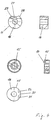
- the cylinder body 14 and 15 are individually in plan views of their axial Sealing surfaces 16 and 17 and each shown in a longitudinal section.
- the cylinder body 15 is additionally in a plan view of its outer end face facing the compression spring 20 displayed.
- the cylinder body 14 sealing the high-pressure chamber 18 is not on it illustrated, the end face facing the high-pressure chamber 18 simply flat.
- At the outer lateral surface is in the region of its sealing web 27 over the entire length of the Cylinder body 14 except a cylinder segment.
- the teeth of the Spur gears 6 and 11. serve as an anti-rotation device for the Pistons 14, 15 by the cylinder body 14 thus sliding along the base 5.
- the formation of the axial sealing surface 16 with the sealing web 27 and in particular the Formation of the pockets 28 and 29 corresponds to that of the axial sealing surface 9 and their pockets.
- the axial sealing surface 17 of the cylinder body 15, which is in the lower part 4 is shown.
- the end face is the cylinder body 15 as a ring pot with a circumferential ring channel formed, which serves as a guide for the compression spring 20.
Landscapes
- Engineering & Computer Science (AREA)
- Mechanical Engineering (AREA)
- General Engineering & Computer Science (AREA)
- Rotary Pumps (AREA)
- Details And Applications Of Rotary Liquid Pumps (AREA)
Description
- Figur 1
- eine Außenzahnradpumpe mit Fördervolumenbegrenzung in einem Längsschnitt,
- Figur 2
- ein Gehäuseteil der Pumpe in der Draufsicht A-A der Figur 1,
- Figur 3
- einen Deckel der Pumpe in der Draufsicht B-B der Figur 1,
- Figur 4
- zwei Zylinderkörper, zwischen denen ein Stirnrad der Pumpe nach Figur 1 drehgelagert ist, und
- Figur 5
- eine perspektivische Ansicht des Deckels der Pumpe nach Figur 3 mit Stirnrad.
Claims (5)
- Außenzahnradpumpe mit Fördervolumenbegrenzung, die Pumpe umfassenda) ein Gehäuse (1, 2),b) wenigstens ein drehangetriebenes Zahnradpaar mit zwei in Eingriff befindlichen Stirnrädern (6, 11), die mit Mantelflächen des Gehäuses (1, 2) und axialen Dichtflächen (9, 10, 16, 17) einen Förderraum bilden, der eine mit einem Pumpeneinlass (3) verbundene Niederdruckseite und eine mit einem Pumpenauslass (4) verbundene Hochdruckseite aufweist, undc) einen Kolben (13, 14, 16), der als Drehlagerung für ein Stirnrad (11) des Zahnradpaars dient und zur Begrenzung des Fördervolumens der Pumpe zusammen mit diesem Stirnrad (11) durch Beaufschlagung mit Fluid der Hochdruckseite gegen die Kraft eines Rückstellelements (20) relativ zu dem anderen Stirnrad (6) des Zahnradpaars verschoben wird,d) wobei in wenigstens einer axialen Dichtfläche (9) an einen Dichtsteg (21) der Dichtfläche (9) grenzend wenigstens zwei Taschen (22, 23) ausgebildet sind, von denen eine erste Tasche (22) den Pumpenauslass (4) und die andere, zweite Tasche (23) den Pumpeneinlass (3) mit einem Bereich tiefsten Zahneingriffs der Stirnräder (6, 11) verbindet,
dadurch gekennzeichnet, dasse) die wenigstens zwei Taschen (22, 23), bezogen auf die axiale Dichtfläche (9), unterschiedliche Tiefen (T1, T2) aufweisen, wobei die Tiefe (T2) der zweiten Tasche (23) geringer ist als die Tiefe (T1) der ersten Tasche (22). - Außenzahnradpumpe nach Anspruch 1, dadurch gekennzeichnet, dass eine maximale Länge des Zahneingriffs der Stimräder (6, 11) das Fünf- bis Zwanzigfache der Tiefe der ersten Tasche (22) oder der zweiten Tasche (23) beträgt.
- Außenzahnradpumpe nach einem der vorhergehenden Ansprüche, dadurch gekennzeichnet, dass die erste Tasche (22), auf der Höhe der Dichtfläche (9) gemessen, eine Fläche einnimmt, die 5 % bis 20 % einer Fläche ausmacht, die von dem an die Dichtfläche (9) grenzenden Stirnrad (6) überstrichen wird.
- Außenzahnradpumpe nach einem der vorhergehenden Ansprüche, dadurch gekennzeichnet, dass jede der axialen Dichtflächen (9, 10, 16, 17) je einen Dichtsteg (21, 24, 27, 30) mit daran grenzenden Taschen (22, 25, 28, 31) auf der Hochdruckseite des Förderraums aufweist.
- Außenzahnradpumpe nach einem der vorhergehenden Ansprüche, dadurch gekennzeichnet, dass jede der axialen Dichtflächen (9, 10, 16, 17) je einen Dichtsteg (21, 24, 27, 30) mit daran grenzenden Taschen (23, 26, 29, 32) auf der Niederdruckseite des Förderraums aufweist.
Applications Claiming Priority (2)
| Application Number | Priority Date | Filing Date | Title |
|---|---|---|---|
| DE19847132A DE19847132C2 (de) | 1998-10-13 | 1998-10-13 | Außenzahnradpumpe mit Fördervolumenbegrenzung |
| DE19847132 | 1998-10-13 |
Publications (2)
| Publication Number | Publication Date |
|---|---|
| EP0994257A1 EP0994257A1 (de) | 2000-04-19 |
| EP0994257B1 true EP0994257B1 (de) | 2002-02-06 |
Family
ID=7884301
Family Applications (1)
| Application Number | Title | Priority Date | Filing Date |
|---|---|---|---|
| EP99119067A Expired - Lifetime EP0994257B1 (de) | 1998-10-13 | 1999-09-30 | Aussenzahnradpumpe mit Fördervolumenbegrenzung |
Country Status (6)
| Country | Link |
|---|---|
| US (1) | US6283735B1 (de) |
| EP (1) | EP0994257B1 (de) |
| JP (1) | JP2000120559A (de) |
| AT (1) | ATE213054T1 (de) |
| DE (2) | DE19847132C2 (de) |
| ES (1) | ES2172279T3 (de) |
Families Citing this family (34)
| Publication number | Priority date | Publication date | Assignee | Title |
|---|---|---|---|---|
| KR100535484B1 (ko) * | 1999-12-31 | 2005-12-07 | 현대자동차주식회사 | 오일 펌프 |
| DE10033950C2 (de) * | 2000-07-13 | 2003-02-27 | Schwaebische Huettenwerke Gmbh | Pumpe mit Magnetkupplung |
| FR2837536B1 (fr) | 2002-03-20 | 2004-06-25 | Renault | Pompe a huile a cylindree modulable pour automobile |
| DE10222131C5 (de) * | 2002-05-17 | 2011-08-11 | Schwäbische Hüttenwerke Automotive GmbH & Co. KG, 73433 | Verdrängerpumpe mit Fördervolumenverstellung |
| AT413140B (de) * | 2003-03-28 | 2005-11-15 | Tcg Unitech Ag | Zahnradpumpe |
| WO2005057013A1 (de) * | 2003-12-10 | 2005-06-23 | Dieter Voigt | Drehzahlabhängige druckregelung von ölpumpen |
| US7281376B2 (en) * | 2005-02-22 | 2007-10-16 | Hybra-Drive Systems, Llc | Hydraulic hybrid powertrain system |
| US8215932B2 (en) * | 2004-04-09 | 2012-07-10 | Limo-Reid, Inc. | Long life telescoping gear pumps and motors |
| US20070227802A1 (en) * | 2004-04-09 | 2007-10-04 | O'brien James A Ii | Hybrid earthmover |
| WO2005100780A2 (en) * | 2004-04-09 | 2005-10-27 | Hybra-Drive Systems, Llc | Variable capacity pump/motor |
| AT500629B8 (de) * | 2004-05-27 | 2007-02-15 | Tcg Unitech Ag | Zahnradpumpe |
| EP1828607A4 (de) * | 2004-12-22 | 2012-12-19 | Magna Powertrain Usa Inc | Gerotorpumpe mit veränderlichem fördervolumen |
| US8011910B2 (en) * | 2005-02-22 | 2011-09-06 | Limo-Reid, Inc. | Low noise gear set for gear pump |
| DE102006011200B4 (de) * | 2006-03-10 | 2014-11-13 | Schwäbische Hüttenwerke Automotive GmbH & Co. KG | Außenzahnradpumpe mit Entlastungstasche |
| DE102006018124A1 (de) | 2006-04-19 | 2007-10-25 | Schwäbische Hüttenwerke Automotive GmbH & Co. KG | Verstellbare Rotationspumpe mit Verschleißminderung |
| US7717690B2 (en) | 2006-08-15 | 2010-05-18 | Tbk Co., Ltd. | Gear pump |
| JP5230971B2 (ja) * | 2006-08-15 | 2013-07-10 | 株式会社Tbk | ギヤポンプ |
| JP5064886B2 (ja) | 2007-05-21 | 2012-10-31 | 株式会社Tbk | ギヤポンプ |
| DE102007033146B4 (de) | 2007-07-13 | 2012-02-02 | Schwäbische Hüttenwerke Automotive GmbH & Co. KG | Verstellventil für die Verstellung des Fördervolumens einer Verdrängerpumpe |
| US20110129359A1 (en) * | 2009-11-30 | 2011-06-02 | Caterpillar Inc. | Variable output pump |
| DE102010003574B4 (de) | 2010-03-31 | 2012-02-09 | Schwäbische Hüttenwerke Automotive GmbH | Pressverbund und Verfahren zur Herstellung eines Pressverbunds |
| DE102010020299B4 (de) | 2010-05-12 | 2013-05-16 | Schwäbische Hüttenwerke Automotive GmbH | Pumpe mit Reibkupplungs-Drehzahlregelung |
| BRPI1001768A2 (pt) * | 2010-05-24 | 2012-01-24 | Jose Luiz Bertazzolli | transmissão continuamente variável |
| TWM396333U (en) * | 2010-08-18 | 2011-01-11 | Sai Ke Ai Luo Technology Co Ltd | Air condensate device |
| US20120051950A1 (en) * | 2010-08-27 | 2012-03-01 | Chang Chun-Hsien | Engine oil pump provided automatic adjustment of oil supply amount |
| DE102011005408B4 (de) | 2011-03-11 | 2014-02-13 | Schwäbische Hüttenwerke Automotive GmbH | Verfahren zur Herstellung einer Fügeverbindung in einer Pumpe oder eines Nockenwellen-Phasenstellers |
| WO2014178483A1 (ko) * | 2013-05-03 | 2014-11-06 | Jang Soon Gil | 가변 용량형 기어 펌프 |
| WO2017026639A1 (ko) * | 2015-08-12 | 2017-02-16 | 장순길 | 가변 용량 기어 펌프 |
| KR102003107B1 (ko) | 2015-08-12 | 2019-07-24 | 장순길 | 가변 용량 펌프 |
| CN105697970A (zh) * | 2016-04-08 | 2016-06-22 | 上海幸福摩托车有限公司 | 一种齿轮式变量泵 |
| CN105782019B (zh) * | 2016-05-04 | 2018-09-04 | 邦语(上海)汽车技术有限公司 | 一种可变量齿轮泵 |
| CN105736350B (zh) * | 2016-05-06 | 2018-02-13 | 上海幸福摩托车有限公司 | 一种齿轮式变量机油泵测试装置 |
| US10113546B2 (en) * | 2016-08-16 | 2018-10-30 | Caterpillar Inc. | Pump for an engine |
| DE102017112699A1 (de) * | 2017-06-08 | 2018-12-13 | Schwäbische Hüttenwerke Automotive GmbH | Außenzahnradpumpe |
Citations (1)
| Publication number | Priority date | Publication date | Assignee | Title |
|---|---|---|---|---|
| JPS5773880A (en) * | 1980-10-23 | 1982-05-08 | Nissan Motor Co Ltd | Variable capacity gear pump |
Family Cites Families (9)
| Publication number | Priority date | Publication date | Assignee | Title |
|---|---|---|---|---|
| US1458204A (en) * | 1923-06-12 | tibbetts | ||
| DE698627C (de) * | 1934-10-31 | 1940-11-14 | Fritz Egersdoerfer | naelen, an deren Muendungen die von der Saugseite her kommenden Zahnluecken vorbeigehen |
| US2149326A (en) * | 1937-04-27 | 1939-03-07 | George W Wilkin | Variable capacity gear pump |
| US2354992A (en) * | 1941-11-11 | 1944-08-01 | Westinghouse Electric & Mfg Co | Gear pump |
| GB781697A (en) * | 1955-04-14 | 1957-08-21 | Borg Warner | Improvements in or relating to gear type pumps |
| US3669577A (en) * | 1970-01-02 | 1972-06-13 | Swan G Swanson | Variable high speed gear pump |
| US4233005A (en) | 1978-01-18 | 1980-11-11 | Lucas Industries Limited | Hydraulic gear pump with recesses in non-working gear flanks |
| DE3528651A1 (de) * | 1985-08-09 | 1987-02-19 | Rohs Hans Guenther Prof Dr Ing | Zahnradpumpe |
| DE4121074A1 (de) * | 1991-06-26 | 1993-01-07 | Pierburg Gmbh | Aussenzahnradpumpe |
-
1998
- 1998-10-13 DE DE19847132A patent/DE19847132C2/de not_active Expired - Fee Related
-
1999
- 1999-09-30 EP EP99119067A patent/EP0994257B1/de not_active Expired - Lifetime
- 1999-09-30 DE DE59900821T patent/DE59900821D1/de not_active Expired - Fee Related
- 1999-09-30 ES ES99119067T patent/ES2172279T3/es not_active Expired - Lifetime
- 1999-09-30 AT AT99119067T patent/ATE213054T1/de not_active IP Right Cessation
- 1999-10-12 JP JP11290329A patent/JP2000120559A/ja active Pending
- 1999-10-13 US US09/417,370 patent/US6283735B1/en not_active Expired - Fee Related
Patent Citations (1)
| Publication number | Priority date | Publication date | Assignee | Title |
|---|---|---|---|---|
| JPS5773880A (en) * | 1980-10-23 | 1982-05-08 | Nissan Motor Co Ltd | Variable capacity gear pump |
Also Published As
| Publication number | Publication date |
|---|---|
| JP2000120559A (ja) | 2000-04-25 |
| EP0994257A1 (de) | 2000-04-19 |
| DE59900821D1 (de) | 2002-03-21 |
| ATE213054T1 (de) | 2002-02-15 |
| ES2172279T3 (es) | 2002-09-16 |
| DE19847132A1 (de) | 2000-04-27 |
| US6283735B1 (en) | 2001-09-04 |
| DE19847132C2 (de) | 2001-05-31 |
Similar Documents
| Publication | Publication Date | Title |
|---|---|---|
| DE19847132C2 (de) | Außenzahnradpumpe mit Fördervolumenbegrenzung | |
| CH252204A (de) | Hydraulisches Getriebe. | |
| WO2012072492A2 (de) | Innenzahnradpumpe | |
| DE3839889C2 (de) | ||
| EP0377617A1 (de) | Zahnradmotor. | |
| DE102005041579B4 (de) | Innenzahnradpumpe mit Füllstück | |
| DE19954728A1 (de) | Drehkolbenvorrichtung | |
| CH682939A5 (de) | Innenzahnradpumpe. | |
| DE4310211A1 (de) | Hydraulische Zahnradmaschine (Pumpe oder Motor) | |
| DE2504562B2 (de) | Hydrostatische Axialkolbenpumpe | |
| DE1653810B2 (de) | Zahnradpumpe | |
| DE1653826B1 (de) | Verschleissausgleichende Innen-Zahnradpumpe | |
| DE3506376A1 (de) | Rotationsmaschine fuer fluessigkeiten | |
| DE19915784A1 (de) | Zahnradpumpe, insbesondere für medizinische Zwecke | |
| DE3112930A1 (de) | Axialkolbenpumpe | |
| DE4135725A1 (de) | Innenzahnradpumpe mit zwei hohlraedern und einem gemeinsamen ritzel | |
| DE2414760A1 (de) | Zahnradpumpe | |
| DE3737961A1 (de) | Innenzahnradpumpe | |
| DE2650908A1 (de) | Innenzahnradmaschine (pumpe oder motor) | |
| AT500629B1 (de) | Zahnradpumpe | |
| DE102010005984B4 (de) | Regelölpumpe | |
| DE2904666A1 (de) | Zahnradpumpe | |
| DE102011006842A1 (de) | Innenzahnradpumpe | |
| DE743191C (de) | Einspritzpumpe fuer Leichtkraftstoffe | |
| DE69501271T2 (de) | Zweirichtungsexzenterpumpe |
Legal Events
| Date | Code | Title | Description |
|---|---|---|---|
| PUAI | Public reference made under article 153(3) epc to a published international application that has entered the european phase |
Free format text: ORIGINAL CODE: 0009012 |
|
| AK | Designated contracting states |
Kind code of ref document: A1 Designated state(s): AT BE CH CY DE DK ES FI FR GB GR IE IT LI LU MC NL PT SE |
|
| AX | Request for extension of the european patent |
Free format text: AL;LT;LV;MK;RO;SI |
|
| 17P | Request for examination filed |
Effective date: 20000308 |
|
| 17Q | First examination report despatched |
Effective date: 20000717 |
|
| AKX | Designation fees paid |
Free format text: AT BE CH CY DE DK ES FI FR GB GR IE IT LI LU MC NL PT SE |
|
| GRAG | Despatch of communication of intention to grant |
Free format text: ORIGINAL CODE: EPIDOS AGRA |
|
| GRAG | Despatch of communication of intention to grant |
Free format text: ORIGINAL CODE: EPIDOS AGRA |
|
| GRAH | Despatch of communication of intention to grant a patent |
Free format text: ORIGINAL CODE: EPIDOS IGRA |
|
| GRAH | Despatch of communication of intention to grant a patent |
Free format text: ORIGINAL CODE: EPIDOS IGRA |
|
| GRAA | (expected) grant |
Free format text: ORIGINAL CODE: 0009210 |
|
| REG | Reference to a national code |
Ref country code: GB Ref legal event code: IF02 |
|
| AK | Designated contracting states |
Kind code of ref document: B1 Designated state(s): AT BE CH CY DE DK ES FI FR GB GR IE IT LI LU MC NL PT SE |
|
| PG25 | Lapsed in a contracting state [announced via postgrant information from national office to epo] |
Ref country code: IE Free format text: LAPSE BECAUSE OF FAILURE TO SUBMIT A TRANSLATION OF THE DESCRIPTION OR TO PAY THE FEE WITHIN THE PRESCRIBED TIME-LIMIT Effective date: 20020206 Ref country code: GR Free format text: LAPSE BECAUSE OF FAILURE TO SUBMIT A TRANSLATION OF THE DESCRIPTION OR TO PAY THE FEE WITHIN THE PRESCRIBED TIME-LIMIT Effective date: 20020206 Ref country code: FI Free format text: LAPSE BECAUSE OF FAILURE TO SUBMIT A TRANSLATION OF THE DESCRIPTION OR TO PAY THE FEE WITHIN THE PRESCRIBED TIME-LIMIT Effective date: 20020206 |
|
| REF | Corresponds to: |
Ref document number: 213054 Country of ref document: AT Date of ref document: 20020215 Kind code of ref document: T |
|
| REG | Reference to a national code |
Ref country code: CH Ref legal event code: EP |
|
| REF | Corresponds to: |
Ref document number: 59900821 Country of ref document: DE Date of ref document: 20020321 |
|
| PG25 | Lapsed in a contracting state [announced via postgrant information from national office to epo] |
Ref country code: PT Free format text: LAPSE BECAUSE OF FAILURE TO SUBMIT A TRANSLATION OF THE DESCRIPTION OR TO PAY THE FEE WITHIN THE PRESCRIBED TIME-LIMIT Effective date: 20020506 Ref country code: DK Free format text: LAPSE BECAUSE OF FAILURE TO SUBMIT A TRANSLATION OF THE DESCRIPTION OR TO PAY THE FEE WITHIN THE PRESCRIBED TIME-LIMIT Effective date: 20020506 |
|
| GBT | Gb: translation of ep patent filed (gb section 77(6)(a)/1977) |
Effective date: 20020501 |
|
| ET | Fr: translation filed | ||
| REG | Reference to a national code |
Ref country code: ES Ref legal event code: FG2A Ref document number: 2172279 Country of ref document: ES Kind code of ref document: T3 |
|
| PG25 | Lapsed in a contracting state [announced via postgrant information from national office to epo] |
Ref country code: LU Free format text: LAPSE BECAUSE OF NON-PAYMENT OF DUE FEES Effective date: 20020930 Ref country code: CY Free format text: LAPSE BECAUSE OF FAILURE TO SUBMIT A TRANSLATION OF THE DESCRIPTION OR TO PAY THE FEE WITHIN THE PRESCRIBED TIME-LIMIT Effective date: 20020930 Ref country code: BE Free format text: LAPSE BECAUSE OF NON-PAYMENT OF DUE FEES Effective date: 20020930 Ref country code: AT Free format text: LAPSE BECAUSE OF NON-PAYMENT OF DUE FEES Effective date: 20020930 |
|
| REG | Reference to a national code |
Ref country code: IE Ref legal event code: FD4D |
|
| PLBE | No opposition filed within time limit |
Free format text: ORIGINAL CODE: 0009261 |
|
| STAA | Information on the status of an ep patent application or granted ep patent |
Free format text: STATUS: NO OPPOSITION FILED WITHIN TIME LIMIT |
|
| 26N | No opposition filed |
Effective date: 20021107 |
|
| BERE | Be: lapsed |
Owner name: *SCHWABISCHE HUTTENWERKE G.M.B.H. Effective date: 20020930 |
|
| PG25 | Lapsed in a contracting state [announced via postgrant information from national office to epo] |
Ref country code: MC Free format text: LAPSE BECAUSE OF NON-PAYMENT OF DUE FEES Effective date: 20030401 |
|
| PGFP | Annual fee paid to national office [announced via postgrant information from national office to epo] |
Ref country code: GB Payment date: 20030822 Year of fee payment: 5 |
|
| PGFP | Annual fee paid to national office [announced via postgrant information from national office to epo] |
Ref country code: DE Payment date: 20030825 Year of fee payment: 5 |
|
| PGFP | Annual fee paid to national office [announced via postgrant information from national office to epo] |
Ref country code: SE Payment date: 20030826 Year of fee payment: 5 Ref country code: NL Payment date: 20030826 Year of fee payment: 5 |
|
| PGFP | Annual fee paid to national office [announced via postgrant information from national office to epo] |
Ref country code: FR Payment date: 20030827 Year of fee payment: 5 |
|
| PGFP | Annual fee paid to national office [announced via postgrant information from national office to epo] |
Ref country code: ES Payment date: 20030922 Year of fee payment: 5 |
|
| PG25 | Lapsed in a contracting state [announced via postgrant information from national office to epo] |
Ref country code: LI Free format text: LAPSE BECAUSE OF NON-PAYMENT OF DUE FEES Effective date: 20030930 Ref country code: CH Free format text: LAPSE BECAUSE OF NON-PAYMENT OF DUE FEES Effective date: 20030930 |
|
| REG | Reference to a national code |
Ref country code: CH Ref legal event code: PL |
|
| PG25 | Lapsed in a contracting state [announced via postgrant information from national office to epo] |
Ref country code: GB Free format text: LAPSE BECAUSE OF NON-PAYMENT OF DUE FEES Effective date: 20040930 |
|
| PG25 | Lapsed in a contracting state [announced via postgrant information from national office to epo] |
Ref country code: SE Free format text: LAPSE BECAUSE OF NON-PAYMENT OF DUE FEES Effective date: 20041001 Ref country code: ES Free format text: LAPSE BECAUSE OF NON-PAYMENT OF DUE FEES Effective date: 20041001 |
|
| PG25 | Lapsed in a contracting state [announced via postgrant information from national office to epo] |
Ref country code: NL Free format text: LAPSE BECAUSE OF NON-PAYMENT OF DUE FEES Effective date: 20050401 Ref country code: DE Free format text: LAPSE BECAUSE OF NON-PAYMENT OF DUE FEES Effective date: 20050401 |
|
| GBPC | Gb: european patent ceased through non-payment of renewal fee |
Effective date: 20040930 |
|
| EUG | Se: european patent has lapsed | ||
| PG25 | Lapsed in a contracting state [announced via postgrant information from national office to epo] |
Ref country code: FR Free format text: LAPSE BECAUSE OF NON-PAYMENT OF DUE FEES Effective date: 20050531 |
|
| NLV4 | Nl: lapsed or anulled due to non-payment of the annual fee |
Effective date: 20050401 |
|
| REG | Reference to a national code |
Ref country code: FR Ref legal event code: ST |
|
| PG25 | Lapsed in a contracting state [announced via postgrant information from national office to epo] |
Ref country code: IT Free format text: LAPSE BECAUSE OF NON-PAYMENT OF DUE FEES Effective date: 20050930 |
|
| REG | Reference to a national code |
Ref country code: ES Ref legal event code: FD2A Effective date: 20041001 |