EP0994021B1 - Method and device for packaging products, and packaging tray therefor - Google Patents
Method and device for packaging products, and packaging tray therefor Download PDFInfo
- Publication number
- EP0994021B1 EP0994021B1 EP99402467A EP99402467A EP0994021B1 EP 0994021 B1 EP0994021 B1 EP 0994021B1 EP 99402467 A EP99402467 A EP 99402467A EP 99402467 A EP99402467 A EP 99402467A EP 0994021 B1 EP0994021 B1 EP 0994021B1
- Authority
- EP
- European Patent Office
- Prior art keywords
- cavities
- lids
- products
- strip
- heat
- Prior art date
- Legal status (The legal status is an assumption and is not a legal conclusion. Google has not performed a legal analysis and makes no representation as to the accuracy of the status listed.)
- Expired - Lifetime
Links
Images


Classifications
-
- B—PERFORMING OPERATIONS; TRANSPORTING
- B65—CONVEYING; PACKING; STORING; HANDLING THIN OR FILAMENTARY MATERIAL
- B65B—MACHINES, APPARATUS OR DEVICES FOR, OR METHODS OF, PACKAGING ARTICLES OR MATERIALS; UNPACKING
- B65B9/00—Enclosing successive articles, or quantities of material, e.g. liquids or semiliquids, in flat, folded, or tubular webs of flexible sheet material; Subdividing filled flexible tubes to form packages
-
- B—PERFORMING OPERATIONS; TRANSPORTING
- B65—CONVEYING; PACKING; STORING; HANDLING THIN OR FILAMENTARY MATERIAL
- B65D—CONTAINERS FOR STORAGE OR TRANSPORT OF ARTICLES OR MATERIALS, e.g. BAGS, BARRELS, BOTTLES, BOXES, CANS, CARTONS, CRATES, DRUMS, JARS, TANKS, HOPPERS, FORWARDING CONTAINERS; ACCESSORIES, CLOSURES, OR FITTINGS THEREFOR; PACKAGING ELEMENTS; PACKAGES
- B65D77/00—Packages formed by enclosing articles or materials in preformed containers, e.g. boxes, cartons, sacks or bags
- B65D77/22—Details
- B65D77/30—Opening or contents-removing devices added or incorporated during filling or closing of containers
Definitions
- the invention relates to a process for packaging products, including food, chemical or pharmaceutical products, to a device for implementing said method, as well as a tray of packaging of products.
- Product storage can be extended by packaging products in vacuum or inert atmosphere, by injection of a neutral gas at the welding station.
- the document EP 0 652 155 A1 describes a method, a device and a packaging container for food, chemical or pharmaceuticals using a first strip of thermoplastic material or thermoformable and a second strip of thermoplastic material or heat-sealable.
- the invention also relates to a device for conditioning products in thermoformed trays, using a single strip of thermoplastic or thermoformable material, comprising means for thermoforming of cavities and associated covers in said strip, means of cutting on three sides around the covers, means of loading the cavities with products, means for folding the covers on the cavities and means for heat sealing the covers to cavities for constituting trays containing said products;
- the invention also relates to a packaging tray of products obtained by implementing a method according to the invention in using a device according to the invention.
- the cavity and the cover have edges with distinct contours, so that provide two tabs capable of being separated to facilitate the opening of the tray.
- a device according to the invention is consisting of online assembly of functional modules supported by load-bearing frames for treating a single strip of thermoplastic material or thermoformable unwound from a roll 1.
- the means of gripping and driving the first strip of thermoplastic material constituted by the horizontal chains are in themselves known, in particular by document FR 2.027.741 in the name of applicant for this application, and do not require further description Detailed.
- thermoplastic strip of roll 1 is unwound flat to arrive in a first zone 2 adapted to receive a device 3 of preheating of the strip of thermoplastic material.
- Preheating is performed for example by means of one or more metal plates having good thermal conductivity.
- metal plates having good thermal conductivity.
- a heating element for example a armored resistor electrically insulated from the metal plate.
- thermoforming zone 4 comprising a thermoforming module 5.
- thermoforming technique used in zone 4 of thermoforming is for example the thermoforming technique known as "negative" simple ", the most common technique in which we first heating the strip of material to be thermoformed by applying it to the contact of a heating plate 5a, then the actual deformation by blowing compressed air through an upper heating plate 5b provided with this effect of appropriate orifices.
- thermoforming module 5 could comply to the technique known as "negative with mechanical assistance", technique in which the film is heated by a contact on either side of this by sandwiching between two thermally regulated plates possibly at different temperatures, then by lowering a piston for example metallic to pre-stretch the strip of performed material and finally by plating the thermoplastic strip on the mold by air injection or compressed gas through the piston provided for this purpose with suitable orifices.
- negative with mechanical assistance technique in which the film is heated by a contact on either side of this by sandwiching between two thermally regulated plates possibly at different temperatures, then by lowering a piston for example metallic to pre-stretch the strip of performed material and finally by plating the thermoplastic strip on the mold by air injection or compressed gas through the piston provided for this purpose with suitable orifices.
- thermoforming line is constituted in double line allowing the simultaneous conditioning in parallel of two trays.
- Each hollow cover A is thus detached from the strip on three sides by only being connected to the strip of thermoformable material by the aforementioned fasteners.
- Guide rails or pads are advantageously provided to support and guide the covers A driven by advancing in successive steps the strip of thermoplastic material.
- the cavities B are filled in a zone 10 for filling products to be packaged, or manually, either by 11 pouring or dosing devices.
- the covers A are folded down over the cavities B around the aforementioned fasteners in a drawdown zone 12 thanks to a medium 13 lid flap.
- thermoformable strip in which the mechanical elements located above of the thermoformable strip have not been shown for clarity, we finds that the folding of the covers A in the area 12 shows contours cut C in the thermoformable strip.
- the covers A folded down and cavities B are then entrained in a welding zone 14, in which two welding bells 15a, 15b come apply to the edges of the covers A and cavity B to weld them so as to make a tight junction.
- the module heat sealing 15a, 15b optionally incorporates an underlayer vacuum depending on the nature of the materials to be welded and the products to be contain (indeed, for certain emulsified products or with a high content of liquid, you can only carry out a partial vacuum under penalty of boiling the product to be packaged).
- the trays are cooled sealed containing the product packaged in a zone 16 of cooling, in which two cooling bells 17a, 17b cool the trays, and in particular the tray edges which have just been welded in zone 14.
- thermoplastic strip At this stage, the cooled trays are still attached to the thermoplastic strip, because the edges of cavities B have not been detached from the thermoplastic strip.
- This separation is carried out in the final cutting zone 18 at by means of cutting discs 19a, 19b counter-rotating.
- Discs 19a, 19b cut the edges of the edges of cavities A, which are wound on recovery drums 20.
- thermoforming phase of zone 4 carried out in module 5 to simultaneously constitute a cavity B and a cover A in the strip of thermoplastic material advancing step by step in advance predetermined according to the dimensions of the corresponding mold.
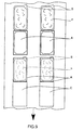
- FIG. 9 represents a preferred embodiment of the invention and illustrates with references identical to those of the preceding figures the setting implementation of the invention by folding the covers A over the cavities B filled with product P, so as to release in the thermoformed strip contours C cut out of separation between successive trays.
- FIG. 10 schematically represents an embodiment preferred tray according to the invention.
- the cover A has rectangular flanges 22 which protrude rounded edges of cavity B while cavity B has a tongue 23 able to be moved away from the corner 22 to allow by simple pull easy opening of the tray.
Abstract
Description
L'invention est relative à un procédé de conditionnement de produits, notamment de produits alimentaires, chimiques ou pharmaceutiques, à un dispositif pour la mise en oeuvre dudit procédé, ainsi qu'à une barquette de conditionnement de produits.The invention relates to a process for packaging products, including food, chemical or pharmaceutical products, to a device for implementing said method, as well as a tray of packaging of products.
On connaít de nombreux procédés et appareillages de conditionnement de produits. Généralement, on utilise deux rouleaux de bandes de matériaux déformables, la première bande étant destinée à être mise en forme pour constituer des cavités et la deuxième bande étant destinée à être soudée sur le périmètre des cavités pour constituer un operculage et un assemblage étanche protégeant les produits alimentaires, chimiques ou pharmaceutiques contenus dans les cavités.We know many processes and packaging equipment of products. Usually two rolls of material strips are used deformable, the first strip being intended to be shaped for constitute cavities and the second strip being intended to be welded to the perimeter of the cavities to form a seal and a sealed assembly protecting the food, chemical or pharmaceutical products contained in the cavities.
La conservation des produits peut être allongée en emballant les produits sous vide ou sous atmosphère inerte, par injection d'un gaz neutre au poste de soudage.Product storage can be extended by packaging products in vacuum or inert atmosphere, by injection of a neutral gas at the welding station.
Le document EP 0 652 155 A1 décrit un procédé, un dispositif et une barquette de conditionnement de produits alimentaires, chimiques ou pharmaceutiques utilisant une première bande de matière thermoplastique ou thermoformable et une deuxième bande de matière thermoplastique ou thermosoudable.The document EP 0 652 155 A1 describes a method, a device and a packaging container for food, chemical or pharmaceuticals using a first strip of thermoplastic material or thermoformable and a second strip of thermoplastic material or heat-sealable.
L'invention a pour but de perfectionner l'art antérieur, en permettant l'utilisation uniquement d'une seule bande de matière thermoplastique ou thermoformable pour conditionner des produits dans des barquettes étanches.The invention aims to improve the prior art, by allowing using only a single strip of thermoplastic material or thermoformable for packaging products in sealed trays.
L'invention a pour objet un procédé selon la revendication 1.The subject of the invention is a method according to claim 1.
Selon d'autres caractéristiques de l'invention :
- le procédé comporte en outre une étape de prédécoupe entre cavités et couvercles associés, pour laisser subsister une ou plusieurs attaches formant charnière de rabattement ;
- le procédé comporte en outre une étape de découpe des lisières bordant les cavités thermosoudées aux couvercles, pour libérer individuellement une ou plusieurs barquettes contenant lesdits produits.
- the method further comprises a step of precut between cavities and associated covers, to allow one or more fasteners to form a hinge;
- the method further comprises a step of cutting the selvedges bordering the heat-sealed cavities with the covers, to individually release one or more trays containing said products.
L'invention a également pour objet un dispositif de conditionnement de produits dans des barquettes thermoformées, en utilisant une bande unique de matière thermoplastique ou thermoformable, comportant des moyens de thermoformage de cavités et de couvercles associés dans ladite bande, des moyens de découpe sur trois côtés autour des couvercles, des moyens de chargement des cavités en produits, des moyens de rabattement des couvercles sur les cavités et des moyens de thermosoudage des couvercles aux cavités pour constituer des barquettes contenant lesdits produits ;The invention also relates to a device for conditioning products in thermoformed trays, using a single strip of thermoplastic or thermoformable material, comprising means for thermoforming of cavities and associated covers in said strip, means of cutting on three sides around the covers, means of loading the cavities with products, means for folding the covers on the cavities and means for heat sealing the covers to cavities for constituting trays containing said products;
Selon d'autres caractéristiques de l'invention :
- le dispositif comporte des moyens de prédécoupe entre cavités et couvercles associés pour laisser subsister une ou plusieurs attaches formant charnière de rabattement.
- le dispositif comporte des moyens de découpe des lisières bordant les cavités thermosoudées aux couvercles.
- les moyens de rabattement des couvercles sur les cavités comprennent au moins un doigt rotatif escamotable.
- les moyens de rabattement des couvercles sur les cavités sont prédéterminés pour relever les couvercles et les rabattre d'un angle supérieur à 90 degrés d'angle.
- the device comprises means for precut between cavities and associated covers to allow one or more fasteners to form a hinge.
- the device comprises means for cutting the selvedges bordering the heat-sealed cavities with the covers.
- the means for folding the covers over the cavities comprise at least one retractable rotary finger.
- the means for folding the covers over the cavities are predetermined to raise the covers and fold them down at an angle greater than 90 degrees of angle.
L'invention a également pour objet une barquette de conditionnement de produits obtenue par la mise en oeuvre d'un procédé selon l'invention en utilisant un dispositif selon l'invention.The invention also relates to a packaging tray of products obtained by implementing a method according to the invention in using a device according to the invention.
Selon d'autres caractéristiques de l'invention, la cavité et le couvercle présentent des rebords présentant des contours distincts, de manière à ménager deux languettes aptes à être écartées pour faciliter l'ouverture de la barquette. According to other features of the invention, the cavity and the cover have edges with distinct contours, so that provide two tabs capable of being separated to facilitate the opening of the tray.
L'invention sera mieux comprise grâce à la description qui va suivre, donnée à titre d'exemple non limitatif en référence aux dessins annexés, dans lesquels :
- la figure 1 représente schématiquement une vue en coupe longitudinale d'un dispositif selon l'invention,
- la figure 2 représente schématiquement et partiellement une vue de dessus d'un dispositif selon l'invention,
- les figures 3 à 8 représentent schématiquement les étapes successives d'un procédé de conditionnement selon l'invention,
- la figure 9 représente schématiquement une vue de dessus explicitant la mise en oeuvre de l'invention,
- la figure 10 représente schématiquement une vue en coupe transversale d'une barquette de conditionnement selon l'invention,
- FIG. 1 schematically represents a view in longitudinal section of a device according to the invention,
- FIG. 2 schematically and partially represents a top view of a device according to the invention,
- FIGS. 3 to 8 schematically represent the successive stages of a packaging process according to the invention,
- FIG. 9 schematically represents a top view explaining the implementation of the invention,
- FIG. 10 schematically represents a cross-sectional view of a packaging container according to the invention,
En référence aux figures 1 et 2, un dispositif selon l'invention est constitué par assemblage en ligne de modules fonctionnels supportés par des châssis porteurs pour traiter une bande unique de matériau thermoplastique ou thermoformable déroulée à partir d'un rouleau 1.Referring to Figures 1 and 2, a device according to the invention is consisting of online assembly of functional modules supported by load-bearing frames for treating a single strip of thermoplastic material or thermoformable unwound from a roll 1.
L'extrémité de la bande enroulée sur le rouleau 1 est entraínée par des chaínes horizontales sur les maillons desquelles sont montées des pinces de préhension de la bande de matière thermoplastique, de manière à entraíner la bande de matière thermoplastique par pas discontinus correspondant à l'avancée de la bande du rouleau dans les cycles successifs du procédé selon l'invention.The end of the strip wound on the roll 1 is driven by horizontal chains on the links of which clamps are mounted gripping the strip of thermoplastic material, so as to cause the strip of thermoplastic material in discontinuous steps corresponding to the advancement of the strip of the roller in the successive cycles of the process according to the invention.
Les moyens de pinçage et d'entraínement de la première bande de matière thermoplastique constitués par les chaínes horizontales sont en eux-mêmes connus, notamment par le document FR 2.027.741 au nom du demandeur de la présente demande, et ne nécessitent pas de description plus détaillée.The means of gripping and driving the first strip of thermoplastic material constituted by the horizontal chains are in themselves known, in particular by document FR 2.027.741 in the name of applicant for this application, and do not require further description Detailed.
La bande thermoplastique du rouleau 1 est déroulée à plat pour arriver
dans une première zone 2 adaptée pour recevoir un dispositif 3 de
préchauffage de la bande de matériau thermoplastique. Le préchauffage est
effectué par exemple au moyen d'une ou plusieurs plaques métalliques
présentant une bonne conductivité thermique. Dans au moins une des
plaques métalliques est noyé un élément chauffant, par exemple une
résistance blindée isolée électriquement par rapport à la plaque métallique.The thermoplastic strip of roll 1 is unwound flat to arrive
in a
Au sortir de la zone 2 réservée au préchauffage, la bande de matière
thermoplastique avance par pas successifs dans une zone 4 de thermoformage
comportant un module 5 de thermoformage.Leaving
La technique de thermoformage utilisée dans la zone 4 de
thermoformage est par exemple la technique de thermoformage dite en "négatif
simple", technique la plus courante dans laquelle on réalise d'abord le
chauffage de la bande de matériau à thermoformer en l'appliquant au contact
d'une plaque chauffante 5a, puis la déformation proprement dite par soufflage
d'air comprimé au travers d'une plaque chauffante 5b supérieure pourvue à
cet effet d'orifices appropriés.The thermoforming technique used in
Alternativement, le module 5 de thermoformage pourrait être conforme
à la technique dite en "négatif avec assistance mécanique", technique dans
laquelle le chauffage du film s'effectue par un contact de part et d'autre de
celui-ci par prise en sandwich entre deux plaques régulées thermiquement
éventuellement à des températures différentes, puis par descente d'un piston
par exemple métallique pour pré-étirer la bande de matériau performé et enfin
par plaquage de la bande thermoplastique sur le moule par injection d'air ou
de gaz comprimé à travers le piston pourvu à cet effet d'orifices appropriés.Alternatively, the
Enfin, dans le cas de matériaux plus rigides, le module 5 de
thermoformage est de préférence conforme à la technique dite en "positif avec
bullage", technique dans laquelle on effectue tout d'abord le chauffage par
contact entre deux plaques régulées thermiquement, puis on déforme la bande
de matériau thermoplastique par aspiration dans la partie basse de l'outillage
de manière à préétirer le film ou la bande thermoplastique et on effectue enfin
le drapage, c'est-à-dire le plaquage du film sur le moule descendu à cet effet
ou au niveau de la bande thermoplastique. Dans cette technique de "bullage"
connue en soi, on obtient avantageusement des parois verticales de formes
régulières avec des angles de barquettes de conditionnement d'une épaisseur
suffisante pour éviter tout perçage ultérieur.Finally, in the case of more rigid materials,
L'essentiel est que l'on réalise lors du thermoformage des paires successives de couvercle A et cavité B associés dans la bande de matière thermoformable déroulée à partir du rouleau 1. The main thing is that we perform during thermoforming of the pairs successive cover A and cavity B associated in the strip of material thermoformable unrolled from the roll 1.
Dans l'exemple non limitatif représenté, la ligne de thermoformage est constituée en ligne double permettant le conditionnement simultané en parallèle de deux barquettes.In the nonlimiting example shown, the thermoforming line is constituted in double line allowing the simultaneous conditioning in parallel of two trays.
En sortie de la zone 4 de thermoformage, une zone 6 de prédécoupe
transversale est prévue pour constituer une charnière entre cavité B et
couvercle A. Un couteau 7a et une enclume 7b coopèrent à cet effet pour
réaliser une coupe transversale à la direction d'avancement de la bande en
laissant subsister deux ou trois attaches entre cavité B et couvercle A.At the exit of
Une zone 8 de découpe sur trois côtés est adjacente à la zone 6 de
prédécoupe pour réaliser une coupe entourant chaque couvercle A sur trois
côtés au moyen d'un couteau à deux lames 9a, 9b présentant un contour en
U.A
Chaque couvercle creux A est ainsi détaché de la bande sur trois côtés en étant uniquement raccordé à la bande de matériau thermoformable par les attaches précitées.Each hollow cover A is thus detached from the strip on three sides by only being connected to the strip of thermoformable material by the aforementioned fasteners.
Des longerons ou patins de guidage non représentés sont avantageusement prévus pour supporter et guider les couvercles A entraínés par l'avancement par pas successifs de la bande de matière thermoplastique.Guide rails or pads, not shown, are advantageously provided to support and guide the covers A driven by advancing in successive steps the strip of thermoplastic material.
Au sortir de la zone 8 de découpe en U sur trois côtés, les cavités B sont
remplies dans une zone 10 de remplissage de produits à conditionner, soit
manuellement, soit par des appareils 11 verseurs ou doseurs.On leaving the U-shaped
Après remplissage, les couvercles A sont rabattus sur les cavités B
autour des attaches précitées dans une zone 12 de rabattement grâce à un
moyen 13 rabatteur de couvercle.After filling, the covers A are folded down over the cavities B
around the aforementioned fasteners in a
Comme moyen 13 rabatteur de couvercle, on peut envisager des doigts
rotatifs basculants destinés à relever les fonds des couvercles A d'un angle
supérieur à 90 degrés, par exemple de l'ordre de 120 degrés, suffisant pour
obtenir l'achèvement de la fermeture du couvercle A par retombée gravitaire
autour des attaches subsistantes.As a
Sur la figure 2, dans laquelle les éléments mécaniques situés au-dessus
de la bande thermoformable n'ont pas été représentés par souci de clarté, on
constate que le rabattement des couvercles A dans la zone 12 fait apparaítre
des contours découpés C dans la bande thermoformable. In FIG. 2, in which the mechanical elements located above
of the thermoformable strip have not been shown for clarity, we
finds that the folding of the covers A in the
Les couvercles A rabattus et cavités B sont entraínés ensuite dans une
zone 14 de soudage, dans laquelle deux cloches 15a, 15b de soudure viennent
s'appliquer sur les rebords des couvercle A et cavité B pour les souder de
manière à réaliser une jonction étanche.The covers A folded down and cavities B are then entrained in a
Comme type de soudure utilisable, on peut envisager une soudure à
cordon plat, une soudure à cordon rayonné, une soudure plane, une soudure
à bourrelet ou une soudure en pointe de diamant. Dans la zone 14, le module
de thermosoudage 15a, 15b incorpore éventuellement un module de mise sous
vide en fonction de la nature des matériaux à souder et des produits à
contenir (en effet, pour certains produits émulsionnés ou à forte teneur en
liquide, on ne peut effectuer qu'un vide partiel sous peine de faire bouillir le
produit à conditionner).As a type of weld that can be used, it is possible to envisage a
flat bead, radiated bead weld, flat weld, weld
with a bead or a diamond point weld. In
Le module de thermosoudage 15a, 15b peut également intégrer en complément ou en remplacement du module de mise sous vide un module de réinjection fonctionnant suivant l'un ou l'autre des systèmes suivants :
- le système à réinjection par buse dans lequel on maintient le couvercle A en position entrebâillée pour permettre la réinjection de gaz et dans lequel on utilise une buse située à l'intérieur de l'outillage de soudure et effectuant la réinjection de gaz à l'intérieur de la cavité B
- ou alternativement la technique de réinjection comme dite "par pastillage", dans laquelle la bande thermoformée préalablement découpée par un module "de pastillage" permet d'effectuer une réinjection de gaz au moyen de conduits situés en position centrale ou en position latérale du moule de soudure, conduits par lesquels le gaz de réinjection débouche à travers l'emplacement en forme de pastille découpé dans la bande thermoformée.
- the nozzle re-injection system in which the cover A is kept in the ajar position to allow gas re-injection and in which a nozzle is used located inside the welding tool and carrying out the gas re-injection inside from cavity B
- or alternatively the reinjection technique as said "by tableting", in which the thermoformed strip previously cut by a "tableting" module makes it possible to carry out a gas reinjection by means of conduits situated in the central position or in the lateral position of the mold. welding, conduits through which the reinjection gas emerges through the pellet-shaped location cut out of the thermoformed strip.
Au sortir de la zone 14 de thermosoudage, on refroidit les barquettes
étanches contenant le produit conditionné dans une zone 16 de
refroidissement, dans laquelle deux cloches de refroidissement 17a, 17b
refroidissent les barquettes, et en particulier les rebords de barquette qui
viennent d'être soudés dans la zone 14.Leaving the
A cette étape, les barquettes refroidies sont encore solidaires de la bande thermoplastique, du fait que les rebords de cavités B n'ont pas été détachés de la bande thermoplastique. At this stage, the cooled trays are still attached to the thermoplastic strip, because the edges of cavities B have not been detached from the thermoplastic strip.
Cette séparation est effectuée dans la zone 18 de découpe finale au
moyen de disques de tranchage 19a, 19b contrarotatifs. Les disques 19a, 19b
découpent les lisières des rebords de cavités A, lesquelles sont enroulées sur
des tambours 20 de récupération.This separation is carried out in the
En raison des séparations transversales correspondant aux contours
découpés, il suffit d'utiliser un tranchage longitudinal (dans le sens de
défilement de la bande thermoplastique) au moyen de disques 19a, 19b, pour
séparer individuellement chaque barquette de produit conditionné et l'évacuer
dans le sens des flèches 21.Due to the transverse separations corresponding to the contours
cut, just use a longitudinal slicing (in the direction of
scrolling of the thermoplastic strip) by means of
En référence aux figures 3 à 8 représentant des vues successives de la
bande thermoplastique vue en coupe transversale, on a représenté sur la
figure 3 la phase de thermoformage de la zone 4 réalisée dans le module 5
pour constituer simultanément une cavité B et un couvercle A dans la bande
de matériau thermoplastique avançant pas-à-pas selon un pas d'avance
prédéterminé en fonction des dimensions du moule correspondant.Referring to Figures 3 to 8 showing successive views of the
thermoplastic strip seen in cross section, there is shown on the
figure 3 the thermoforming phase of
Sur la figure 4, on effectue la découpe transversale de la zone 6 au
moyen du poinçon 7a et de l'enclume 7b, de manière à laisser subsister de
faibles attaches entre couvercle A et cavité B associés.In FIG. 4, the transverse cutting of
Sur la figure 5, on effectue la découpe entourante en U de la zone 8 sur
trois côtés au moyen du poinçon 9a de découpe en U et de l'enclume 9b, de
manière à détacher entièrement les trois côtés correspondants au rebord
extérieur des couvercles A.In FIG. 5, the surrounding U-shaped cut is made of the
Sur la figure 6, on effectue le remplissage des cavités B par un produit
P. Le produit P remplit au moins partiellement chaque cavité B sans toutefois
déborder de celle-ci. Divers moyens de remplissage peuvent être prévus au
poste 10 de remplissage, par exemple l'utilisation d'un appareil 11 de
remplissage de produit P.In FIG. 6, the cavities B are filled with a product
P. The product P at least partially fills each cavity B without however
overflow from it. Various filling means can be provided for
filling
Sur la figure 7, on effectue dans la zone 12 le rabattement des couvercles A sur les cavités B autour des points d'attache matérialisant une charnière. Un moyen 13 de rabattement, par exemple un doigt poussoir escamotable à chaque pas d'avance, agit de préférence sur les fonds de couvercle A, pour que les rebords de couvercle A viennent s'appliquer sur les rebords de cavité B. In FIG. 7, the drawdown of the covers A on the cavities B around the attachment points materializing a hinge. A folding means 13, for example a push finger retractable at each step in advance, preferably acts on the cover A, so that the edges of cover A are applied to the cavity edges B.
Sur la figure 8, on effectue au poste 14 de thermosoudage une
éventuelle mise sous vide ou une injection de gaz neutre au moins d'une buse
22 d'injection à travers l'ouverture entrebâillée de la barquette, puis on
effectue le thermosoudage des rebords à l'aide des cloches 15a, 15b de
thermosoudage.In Figure 8, is carried out at the
On refroidit enfin les barquettes soudées et en particulier leurs rebords
soudés au poste 16 de refroidissement à l'aide des cloches 17a, 17b de
refroidissement.Finally, the welded trays and in particular their edges are cooled.
welded to the
La figure 9 représente un mode préféré de réalisation de l'invention et illustre avec des références identiques à celles des figures précédentes la mise en oeuvre de l'invention par rabattement des couvercles A sur les cavités B remplies du produit P, de manière à dégager dans la bande thermoformée des contours C découpés de séparation entre barquettes successives.FIG. 9 represents a preferred embodiment of the invention and illustrates with references identical to those of the preceding figures the setting implementation of the invention by folding the covers A over the cavities B filled with product P, so as to release in the thermoformed strip contours C cut out of separation between successive trays.
La figure 10 représente schématiquement un mode de réalisation préféré de barquette selon l'invention.FIG. 10 schematically represents an embodiment preferred tray according to the invention.
Le couvercle A présente des rebords rectangulaires 22 qui dépassent
des rebords arrondis de la cavité B tandis que la cavité B présente une
languette 23 apte à être écartée du coin 22 pour permettre par simple traction
une ouverture facile de la barquette.The cover A has
L'invention décrite en référence à un mode de réalisation particulier n'y est nullement limitée, mais couvre au contraire toute modification de forme et toute variation de réalisation dans le cadre et l'esprit de l'invention, permettant l'utilisation d'une bande unique de matière thermoformable pour conditionner un produit en barquettes assemblées chacune de manière étanche à partir d'une cavité et d'un couvercle.The invention described with reference to a particular embodiment does not is in no way limited, but on the contrary covers any modification of form and any variation in implementation within the scope and spirit of the invention, allowing the use of a single strip of thermoformable material for packaging a product in trays, each assembled in such a way waterproof from a cavity and a cover.
Claims (10)
- Method for packaging products (P) in heat-moulded trays using a single strip of thermoplastic or heat-mouldable material (1), including steps (4) of heat-moulding associated lids (A) and cavities (B) in said strip, of cutting (B) on three sides around the lids (A), the cavities remaining integral with said strip, of charging (10) the cavities (B) with products (P), of folding down (12) the lids (A) over the cavities (B) and of heat-welding (14) the lids (A) to the cavities (B) in order to form trays containing said products (P).
- Method according to Claim 1, including, also, a step (6) of preliminary cutting between associated lids (A) and cavities (B) in order to leave one or more attachments remaining, forming a folding-down hinge.
- Method according to Claim 1 or Claim 2, including, also, a step (18) of cutting the edges bordering the cavities (B) heat-welded to the lids (A) in order individually to release one or more trays containing said products (P).
- Device for implementing the method according to Claim 1, including means (5) for heat-moulding associated lids (A) and cavities (B) in said strip, means for cutting on three sides (9a, 9b) around the lids (A), means (11) for charging the cavities with products (P), means (13) for folding down the lids (A) over the cavities (B) and means for heat-welding the lids (A) to the cavities (B) in order to form trays containing said products (P).
- Device according to Claim 4, including means (7a, 7b) for preliminary cutting between associated lids (A) and cavities (B) in order to leave one or more attachments remaining, forming a folding-down hinge.
- Device according to Claim 4 or Claim 5, including means (19a, 19b) for cutting the edges bordering the cavities (B) heat-welded to the lids (A).
- Device according to any one of Claims 4 to 6, in which the means (13) for folding down the lids (A) over the cavities (B) comprise at least one retractable rotary finger.
- Device according to any one of Claims 4 to 7, in which the means (13) for folding down the lids (A) over the cavities (B) are pre-set in order to lift the lids and fold them down at an angle greater than 90° of angle.
- Tray, for packaging products, obtained by implementing a method according to any one of Claims 1 to 3 or by using a device according to any one of Claims 4 to 7.
- Tray according to Claim 9, characterized in that the cavity (B) and the lid (A) have rims that have distinct contours so as to form two tabs (22, 23) suitable for being moved apart in order to facilitate opening of the tray.
Applications Claiming Priority (2)
| Application Number | Priority Date | Filing Date | Title |
|---|---|---|---|
| FR9812981A FR2784654B1 (en) | 1998-10-16 | 1998-10-16 | PROCESS AND DEVICE FOR PACKAGING PRODUCTS AND CORRESPONDING PACKAGING CONTAINERS |
| FR9812981 | 1998-10-16 |
Publications (2)
| Publication Number | Publication Date |
|---|---|
| EP0994021A1 EP0994021A1 (en) | 2000-04-19 |
| EP0994021B1 true EP0994021B1 (en) | 2003-12-10 |
Family
ID=9531639
Family Applications (1)
| Application Number | Title | Priority Date | Filing Date |
|---|---|---|---|
| EP99402467A Expired - Lifetime EP0994021B1 (en) | 1998-10-16 | 1999-10-08 | Method and device for packaging products, and packaging tray therefor |
Country Status (6)
| Country | Link |
|---|---|
| US (1) | US6282870B1 (en) |
| EP (1) | EP0994021B1 (en) |
| AT (1) | ATE256031T1 (en) |
| DE (1) | DE69913462T2 (en) |
| ES (1) | ES2213341T3 (en) |
| FR (1) | FR2784654B1 (en) |
Families Citing this family (14)
| Publication number | Priority date | Publication date | Assignee | Title |
|---|---|---|---|---|
| US20020096431A1 (en) * | 1999-09-01 | 2002-07-25 | Pierre Sevigny | Apparatus for the manufacture of a disposable electrophoresis cassette and method thereof |
| DE60008889T2 (en) * | 1999-09-09 | 2005-03-17 | Dairygold Technologies Ltd. | PROCESS FOR PACKAGING FOODS |
| DE10033796C1 (en) * | 2000-07-12 | 2001-10-11 | Illig Maschinenbau Adolf | Production of blister packaging made from thermoplastic comprises sealing blister edges with support part, cooling, and heating transition region between dome and support part |
| US7244221B2 (en) * | 2004-05-21 | 2007-07-17 | Rogar Capital Corporation | Method and apparatus for simultaneously forming an articulable container with fold creases |
| US7987655B2 (en) * | 2008-04-22 | 2011-08-02 | Rovema Packaging Machines, Lp | Tubular bagging machine and method |
| FR2961428B1 (en) * | 2010-06-18 | 2013-04-26 | Sidel Participations | TOOL MODULE FOR FASTENING AT LEAST ONE CARDBOARD CUTTER |
| DE102013204160A1 (en) * | 2013-03-11 | 2014-09-11 | Multivac Sepp Haggenmüller Gmbh & Co. Kg | Packaging system with latching station and method |
| CN105690820B (en) * | 2016-01-27 | 2018-05-04 | 蚌埠市众邦包装厂 | A kind of vertical shallow base pressure plastic packing box continuity processing unit (plant) |
| CN105563795B (en) * | 2016-01-27 | 2018-03-27 | 蚌埠市众邦包装厂 | A kind of horizontal shallow base pressure plastic packing box control system for processing |
| CN105643964B (en) * | 2016-01-27 | 2018-01-23 | 蚌埠市众邦包装厂 | A kind of horizontal shallow base pressure plastic packing box continuity process equipment |
| JP6152201B1 (en) * | 2016-06-29 | 2017-06-21 | Ckd株式会社 | Blister packing machine |
| US11192671B2 (en) * | 2017-01-04 | 2021-12-07 | Church & Dwight, Co., Inc. | System and a related method for forming a multi-chamber package |
| USD964862S1 (en) | 2018-08-21 | 2022-09-27 | Intercontinental Great Brands Llc | Tray |
| ES2956226T3 (en) | 2018-08-21 | 2023-12-15 | Intercontinental Great Brands Llc | Food Storage Tray |
Family Cites Families (9)
| Publication number | Priority date | Publication date | Assignee | Title |
|---|---|---|---|---|
| GB1286151A (en) | 1969-01-03 | 1972-08-23 | Lucas Industries Ltd | Plunger operated switches |
| SE434131B (en) * | 1979-09-12 | 1984-07-09 | Tetra Pak Int | SET FOR MANUFACTURING CONTAINERS INTENDED FOR A UNDERPRESSED FILLING GOODS, AND CONTAINERS FOR A UNDERPRESSED FILLING LOAD. |
| US4387551A (en) * | 1979-09-21 | 1983-06-14 | Maryland Cup Corporation | Heat-sealable, ovenable containers and method of manufacture |
| US5007231A (en) * | 1985-08-16 | 1991-04-16 | Plm Ab | Container |
| US5009056A (en) * | 1987-01-16 | 1991-04-23 | Porteous Don D | Method for preparing finger mountable dispensing cups |
| US5369937A (en) * | 1993-05-10 | 1994-12-06 | Joule' Inc. | Continuous casting and packaging |
| US5419096A (en) * | 1993-07-28 | 1995-05-30 | World Class Packaging Systems, Inc. | Packaging method and apparatus for packaging large meat products in a desired gaseous atmosphere |
| FR2712253B1 (en) * | 1993-11-10 | 1996-01-19 | Mecaplastic | Method and device for packaging food, chemical or pharmaceutical products and corresponding packaging trays. |
| US5496250A (en) * | 1994-04-25 | 1996-03-05 | Fielder; Larry D. | Method for forming tray type cartons |
-
1998
- 1998-10-16 FR FR9812981A patent/FR2784654B1/en not_active Expired - Fee Related
-
1999
- 1999-10-08 AT AT99402467T patent/ATE256031T1/en not_active IP Right Cessation
- 1999-10-08 EP EP99402467A patent/EP0994021B1/en not_active Expired - Lifetime
- 1999-10-08 ES ES99402467T patent/ES2213341T3/en not_active Expired - Lifetime
- 1999-10-08 DE DE69913462T patent/DE69913462T2/en not_active Expired - Lifetime
- 1999-10-18 US US09/419,802 patent/US6282870B1/en not_active Expired - Fee Related
Also Published As
| Publication number | Publication date |
|---|---|
| DE69913462D1 (en) | 2004-01-22 |
| US6282870B1 (en) | 2001-09-04 |
| FR2784654B1 (en) | 2001-01-12 |
| DE69913462T2 (en) | 2004-10-07 |
| EP0994021A1 (en) | 2000-04-19 |
| ES2213341T3 (en) | 2004-08-16 |
| ATE256031T1 (en) | 2003-12-15 |
| FR2784654A1 (en) | 2000-04-21 |
Similar Documents
| Publication | Publication Date | Title |
|---|---|---|
| EP0994021B1 (en) | Method and device for packaging products, and packaging tray therefor | |
| EP0652155B1 (en) | Method and device for packaging food products, chemical or pharmaceutical products, and corresponding packaging tray | |
| EP0252791B1 (en) | Presentation tray in the shape of a packaging container | |
| EP2956292B1 (en) | Packaging of a group of at least two containers made of plastic material | |
| FR2464815A1 (en) | PROCESS FOR MANUFACTURING A GAS-TIGHT PACKAGING | |
| EP3481737B1 (en) | 3-d flexible bag to be filled for biopharmaceutical fluids and method for creating such a bag | |
| WO1986002055A1 (en) | Sealed package, method for manufacturing and utilization of said package | |
| US6719015B2 (en) | Apparatus and process for manufacturing a filled flexible pouch | |
| CA3164589A1 (en) | Food product package formed by a sheet sealed on itself, method for manufacturing and filling such a packaging and blank | |
| CH621744A5 (en) | ||
| EP0388310A1 (en) | Package for packaging a food product, process and apparatus for its manufacture | |
| WO2013057392A1 (en) | Method of producing a packaging box and a box obtained according to this method | |
| EP2238037B1 (en) | Method for packaging a pasty product in an easily opened, sealed packaging made of plastic material | |
| CH626561A5 (en) | Method for the manufacture of an assembly formed by a covering sheet and a support, device for implementing the method, and container obtained | |
| FR3056195A1 (en) | OPERATING DEVICE WITH CONTAINER MEDIA MEANS AND MOBILE HEATER BLOCK AND CORRESPONDING METHOD | |
| EP0062571A1 (en) | Process and device for piercing the lid of a recipient, and manufacturing appliance for the device | |
| EP2722155A1 (en) | Device for manufacturing containers by thermoforming | |
| EP1340678A1 (en) | Sealed container for food products | |
| FR2763015A1 (en) | PROCESS FOR WELDING THERMOFORMED SHEETS OF PLASTIC MATERIAL AND MACHINE FOR CARRYING OUT SAID METHOD | |
| BE900166A (en) | Packaging of very small quantities of liqs. etc. - by sealing plastics sheets around product without contaminating seal | |
| FR2663910A1 (en) | COMPOSITE STRIP AND INSTALLATION FOR MANUFACTURING THERMOFORMED STERILE PACKAGES. | |
| FR2914278A1 (en) | Perishable food product i.e. fruit, conditioning method for packaging fruit, involves thermally-welding one film on container for ensuring hermetic closure, and partially welding another film on container before removing former film | |
| CH619408A5 (en) | Method for packaging in a sterile environment and installation for implementing the method | |
| EP0885805A1 (en) | Method and device for thermoforming, filling and closing plastic cups | |
| FR2898339A1 (en) | METHOD AND MACHINE FOR FORMING AND THERMOSAGING A PLASTIC FILM ON AN ARTICLE, SUCH AS A STERILE BOX FOR THE CULTURE OF MICROORGANISMS, AND ARTICLE THUS OBTAINED |
Legal Events
| Date | Code | Title | Description |
|---|---|---|---|
| PUAI | Public reference made under article 153(3) epc to a published international application that has entered the european phase |
Free format text: ORIGINAL CODE: 0009012 |
|
| AK | Designated contracting states |
Kind code of ref document: A1 Designated state(s): AT BE CH CY DE DK ES FI FR GB GR IE IT LI LU MC NL PT SE |
|
| AX | Request for extension of the european patent |
Free format text: AL;LT;LV;MK;RO;SI |
|
| 17P | Request for examination filed |
Effective date: 20000930 |
|
| AKX | Designation fees paid |
Free format text: AT BE CH CY DE DK ES FI FR GB GR IE IT LI LU MC NL PT SE |
|
| GRAH | Despatch of communication of intention to grant a patent |
Free format text: ORIGINAL CODE: EPIDOS IGRA |
|
| GRAS | Grant fee paid |
Free format text: ORIGINAL CODE: EPIDOSNIGR3 |
|
| GRAA | (expected) grant |
Free format text: ORIGINAL CODE: 0009210 |
|
| AK | Designated contracting states |
Kind code of ref document: B1 Designated state(s): AT BE CH CY DE DK ES FI FR GB GR IE IT LI LU MC NL PT SE |
|
| PG25 | Lapsed in a contracting state [announced via postgrant information from national office to epo] |
Ref country code: NL Free format text: LAPSE BECAUSE OF FAILURE TO SUBMIT A TRANSLATION OF THE DESCRIPTION OR TO PAY THE FEE WITHIN THE PRESCRIBED TIME-LIMIT Effective date: 20031210 Ref country code: IT Free format text: LAPSE BECAUSE OF FAILURE TO SUBMIT A TRANSLATION OF THE DESCRIPTION OR TO PAY THE FEE WITHIN THE PRESCRIBED TIME-LIMIT;WARNING: LAPSES OF ITALIAN PATENTS WITH EFFECTIVE DATE BEFORE 2007 MAY HAVE OCCURRED AT ANY TIME BEFORE 2007. THE CORRECT EFFECTIVE DATE MAY BE DIFFERENT FROM THE ONE RECORDED. Effective date: 20031210 Ref country code: IE Free format text: LAPSE BECAUSE OF FAILURE TO SUBMIT A TRANSLATION OF THE DESCRIPTION OR TO PAY THE FEE WITHIN THE PRESCRIBED TIME-LIMIT Effective date: 20031210 Ref country code: FI Free format text: LAPSE BECAUSE OF FAILURE TO SUBMIT A TRANSLATION OF THE DESCRIPTION OR TO PAY THE FEE WITHIN THE PRESCRIBED TIME-LIMIT Effective date: 20031210 Ref country code: CY Free format text: LAPSE BECAUSE OF FAILURE TO SUBMIT A TRANSLATION OF THE DESCRIPTION OR TO PAY THE FEE WITHIN THE PRESCRIBED TIME-LIMIT Effective date: 20031210 Ref country code: AT Free format text: LAPSE BECAUSE OF FAILURE TO SUBMIT A TRANSLATION OF THE DESCRIPTION OR TO PAY THE FEE WITHIN THE PRESCRIBED TIME-LIMIT Effective date: 20031210 |
|
| REG | Reference to a national code |
Ref country code: GB Ref legal event code: FG4D Free format text: NOT ENGLISH |
|
| REG | Reference to a national code |
Ref country code: CH Ref legal event code: EP |
|
| REG | Reference to a national code |
Ref country code: IE Ref legal event code: FG4D Free format text: FRENCH |
|
| REF | Corresponds to: |
Ref document number: 69913462 Country of ref document: DE Date of ref document: 20040122 Kind code of ref document: P |
|
| PG25 | Lapsed in a contracting state [announced via postgrant information from national office to epo] |
Ref country code: SE Free format text: LAPSE BECAUSE OF FAILURE TO SUBMIT A TRANSLATION OF THE DESCRIPTION OR TO PAY THE FEE WITHIN THE PRESCRIBED TIME-LIMIT Effective date: 20040310 Ref country code: GR Free format text: LAPSE BECAUSE OF FAILURE TO SUBMIT A TRANSLATION OF THE DESCRIPTION OR TO PAY THE FEE WITHIN THE PRESCRIBED TIME-LIMIT Effective date: 20040310 Ref country code: DK Free format text: LAPSE BECAUSE OF FAILURE TO SUBMIT A TRANSLATION OF THE DESCRIPTION OR TO PAY THE FEE WITHIN THE PRESCRIBED TIME-LIMIT Effective date: 20040310 |
|
| GBT | Gb: translation of ep patent filed (gb section 77(6)(a)/1977) |
Effective date: 20040324 |
|
| NLV1 | Nl: lapsed or annulled due to failure to fulfill the requirements of art. 29p and 29m of the patents act | ||
| REG | Reference to a national code |
Ref country code: IE Ref legal event code: FD4D |
|
| REG | Reference to a national code |
Ref country code: ES Ref legal event code: FG2A Ref document number: 2213341 Country of ref document: ES Kind code of ref document: T3 |
|
| PG25 | Lapsed in a contracting state [announced via postgrant information from national office to epo] |
Ref country code: LU Free format text: LAPSE BECAUSE OF NON-PAYMENT OF DUE FEES Effective date: 20041008 |
|
| PLBE | No opposition filed within time limit |
Free format text: ORIGINAL CODE: 0009261 |
|
| STAA | Information on the status of an ep patent application or granted ep patent |
Free format text: STATUS: NO OPPOSITION FILED WITHIN TIME LIMIT |
|
| PG25 | Lapsed in a contracting state [announced via postgrant information from national office to epo] |
Ref country code: MC Free format text: LAPSE BECAUSE OF NON-PAYMENT OF DUE FEES Effective date: 20041031 Ref country code: LI Free format text: LAPSE BECAUSE OF NON-PAYMENT OF DUE FEES Effective date: 20041031 Ref country code: CH Free format text: LAPSE BECAUSE OF NON-PAYMENT OF DUE FEES Effective date: 20041031 Ref country code: BE Free format text: LAPSE BECAUSE OF NON-PAYMENT OF DUE FEES Effective date: 20041031 |
|
| 26N | No opposition filed |
Effective date: 20040913 |
|
| BERE | Be: lapsed |
Owner name: *MECAPLASTIC Effective date: 20041031 |
|
| REG | Reference to a national code |
Ref country code: CH Ref legal event code: PL |
|
| BERE | Be: lapsed |
Owner name: *MECAPLASTIC Effective date: 20041031 |
|
| PG25 | Lapsed in a contracting state [announced via postgrant information from national office to epo] |
Ref country code: PT Free format text: LAPSE BECAUSE OF NON-PAYMENT OF DUE FEES Effective date: 20040510 |
|
| PGFP | Annual fee paid to national office [announced via postgrant information from national office to epo] |
Ref country code: DE Payment date: 20101022 Year of fee payment: 12 |
|
| PGFP | Annual fee paid to national office [announced via postgrant information from national office to epo] |
Ref country code: GB Payment date: 20101021 Year of fee payment: 12 |
|
| REG | Reference to a national code |
Ref country code: FR Ref legal event code: CD |
|
| PGFP | Annual fee paid to national office [announced via postgrant information from national office to epo] |
Ref country code: FR Payment date: 20111103 Year of fee payment: 13 Ref country code: ES Payment date: 20111026 Year of fee payment: 13 |
|
| GBPC | Gb: european patent ceased through non-payment of renewal fee |
Effective date: 20121008 |
|
| REG | Reference to a national code |
Ref country code: FR Ref legal event code: ST Effective date: 20130628 |
|
| PG25 | Lapsed in a contracting state [announced via postgrant information from national office to epo] |
Ref country code: GB Free format text: LAPSE BECAUSE OF NON-PAYMENT OF DUE FEES Effective date: 20121008 Ref country code: DE Free format text: LAPSE BECAUSE OF NON-PAYMENT OF DUE FEES Effective date: 20130501 |
|
| REG | Reference to a national code |
Ref country code: DE Ref legal event code: R119 Ref document number: 69913462 Country of ref document: DE Effective date: 20130501 |
|
| PG25 | Lapsed in a contracting state [announced via postgrant information from national office to epo] |
Ref country code: FR Free format text: LAPSE BECAUSE OF NON-PAYMENT OF DUE FEES Effective date: 20121031 |
|
| REG | Reference to a national code |
Ref country code: ES Ref legal event code: FD2A Effective date: 20140116 |
|
| PG25 | Lapsed in a contracting state [announced via postgrant information from national office to epo] |
Ref country code: ES Free format text: LAPSE BECAUSE OF NON-PAYMENT OF DUE FEES Effective date: 20121009 |