EP0993884A2 - Vorrichtung und Verfahren zum Bördeln der Kanten eines Bleches - Google Patents
Vorrichtung und Verfahren zum Bördeln der Kanten eines Bleches Download PDFInfo
- Publication number
- EP0993884A2 EP0993884A2 EP19990119897 EP99119897A EP0993884A2 EP 0993884 A2 EP0993884 A2 EP 0993884A2 EP 19990119897 EP19990119897 EP 19990119897 EP 99119897 A EP99119897 A EP 99119897A EP 0993884 A2 EP0993884 A2 EP 0993884A2
- Authority
- EP
- European Patent Office
- Prior art keywords
- edge
- pattern
- flangeing
- roller
- workpiece
- Prior art date
- Legal status (The legal status is an assumption and is not a legal conclusion. Google has not performed a legal analysis and makes no representation as to the accuracy of the status listed.)
- Withdrawn
Links
- 239000002184 metal Substances 0.000 title claims abstract description 25
- 238000000034 method Methods 0.000 title claims description 5
- 230000002093 peripheral effect Effects 0.000 claims abstract description 11
- 230000015572 biosynthetic process Effects 0.000 claims description 8
- 238000005755 formation reaction Methods 0.000 claims description 8
- 238000003825 pressing Methods 0.000 claims description 3
- 238000005096 rolling process Methods 0.000 claims description 2
- 239000007787 solid Substances 0.000 claims description 2
- 230000001360 synchronised effect Effects 0.000 claims description 2
- 238000004519 manufacturing process Methods 0.000 description 3
- 238000006243 chemical reaction Methods 0.000 description 2
- 230000000694 effects Effects 0.000 description 2
- 230000005540 biological transmission Effects 0.000 description 1
- 230000002860 competitive effect Effects 0.000 description 1
- 238000010276 construction Methods 0.000 description 1
- 230000001419 dependent effect Effects 0.000 description 1
- 238000005516 engineering process Methods 0.000 description 1
- 238000005555 metalworking Methods 0.000 description 1
- 239000011347 resin Substances 0.000 description 1
- 229920005989 resin Polymers 0.000 description 1
- 230000000717 retained effect Effects 0.000 description 1
Images
Classifications
-
- B—PERFORMING OPERATIONS; TRANSPORTING
- B21—MECHANICAL METAL-WORKING WITHOUT ESSENTIALLY REMOVING MATERIAL; PUNCHING METAL
- B21D—WORKING OR PROCESSING OF SHEET METAL OR METAL TUBES, RODS OR PROFILES WITHOUT ESSENTIALLY REMOVING MATERIAL; PUNCHING METAL
- B21D19/00—Flanging or other edge treatment, e.g. of tubes
- B21D19/02—Flanging or other edge treatment, e.g. of tubes by continuously-acting tools moving along the edge
Definitions
- the present invention relates to a machine and a process for flangeing the edges of sheet metal work pieces or blanks.
- Machines for flangeing the edges of metal sheets comprising a flangeing head equipped with a flangeing roller free to rotate about a vertical axis, fixing means for a work piece having a sheet metal peripheral edge to be flanged, and drive means for causing relative movement between the fixing means and the flangeing head in such a way that the roller follows the peripheral edge to be flanged.
- Examples of arrangements of this general type are described in JP-A-09220620, SU-A-1196072, EP-A-0698430.
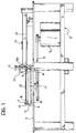
- the reference numeral 10 generally indicates a support structure with an upper horizontal plane 11; on the structure 10, beneath the plane 11, there is mounted a motor unit 12 which, via a transmission 13, drives a rotatable table 14 mounted rotatably on the upper part of plane 11, to turn about a vertical axis y.
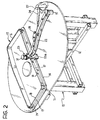
- a shaped pattern 15 preferably of resin, forming a perimeteral wall 16 which extends vertically.
- the wall 16 has an essentially vertical outer surface 17 and an essentially horizontal upper surface 18; these surfaces are disposed at an angle forming an edge or corner 19 ( Figures 4 and 5) which defines a peripheral fold line for the formation of a perimeteral flange on a sheet metal workpiece 20 associated from above with the pattern 15. It is intended, however, that such surfaces can also be inclined differently from what has been illustrated in the present example, forming between them angles different from 90° or variable along the periphery of the pattern, depending on the shape of the workpiece 20 to be flanged and the requirements of the designs.
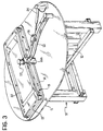
- the perimeteral wall 16 is dimensioned and shaped in such a way as to present an outline corresponding to the associated workpiece 20 the sheet metal edges 21 of which are to be folded or flanged perpendicularly to the main plane in which the workpiece lies, starting from an undeformed condition ( Figure 4) in which the edges project horizontally from the vertical wall 16 of the shaped pattern 15, to end up at a final flanged condition ( Figure 5) in which the edges are folded horizontally against the vertical outer surface 17 as will be explained in more detail herein below.
- the height of the vertical wall 16 measured with respect to the rotatable table 14, can be constant or variable along its perimeter as in the example of Figures 2 and 3, depending on the particular shape of the workpiece to be worked.
- the sheet metal workpiece 20 to be flanged is retained on the shaped pattern 15 preferably by means of magnets (not illustrated for simplicity) and centred in the correct position by means of a plurality of reference pins (not illustrated) projecting vertically from the shaped model which are inserted into corresponding apertures (not illustrated) preliminarily provided in the workpiece.
- an arm 22 turnable about a vertical axis y'; at its free end 22a the arm 22 carries a flangeing head, generally indicated 23, which in use is thrust against the wall 16 by means of an actuator 24, in this example a hydraulic cylinder, having a first end pivoted at 25 to the fixed structure 10 and a second end pivoted at 26 to the pivoted arm 22.
- an actuator 24 in this example a hydraulic cylinder, having a first end pivoted at 25 to the fixed structure 10 and a second end pivoted at 26 to the pivoted arm 22.
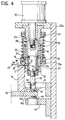
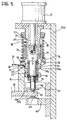
- the flangeing head 23 comprises a vertically extendable device generally indicated 28 mounted on the free end 22a of the pivoted arm.
- the device 28 comprises an upper cylindrical element 29 fixed with respect to the end 22a and a lower movable element 30 telescopically guided by the upper element 29 and actuated by a hydraulic cylinder 31 fixed to the end 22a of the arm 22.
- a flangeing roller 27 is fixed axially in a freely rotatable manner about the lower moveable element 30 so as to be displaceable vertically together with it.
- the roller 27 has the shape of a solid of rotation in which there is a pair of radially projecting vertically spaced annular formations 32 and 33.
- the lower annular formation 32 is able to roll against the vertical surface 17 of the walls 16, whilst the upper formation 33, which serves to fold the sheet metal edge 21, forms an upper cylindrical portion 33a which joins with a lower downwardly tapered portion 33b at an angle of about 45°.
- the flangeing head includes a second auxiliary roller 34 freely rotatable about the upper element 29 of the telescopic device 28, which serves to exert a downward pressure on the metal sheet 20, pressing it against the upper support surface 18 of the wall 16 close to the edge 21 to be deformed, for the purpose of maintaining the peripheral part of the metal sheet in the correct position against the shaped body 15.
- the auxiliary roller 34 is pressed downwardly by a spring 35, the bottom of which acts on a bearing ring 36 and the top of which engages against a biasing ring nut 37 threadedly coupled to the fixed cylindrical element 29 to adjust the position of the ring nut and therefore the thrust on the ring 36; between this ring and the auxiliary roller 34 are interposed rolling elements 38.
- the lower end 39 of the movable telescopic element 30 is slidably guided in a cylindrical bush 40 supported by the arm 22 by means of a first horizontal bracket 41 the bottom of which carries a support ball 42 which rolls against the upper horizontal surface 14a of the rotatable table 14.
- a second horizontal bracket 43 is fixed to the arm 22 and carries a support ball 44 which rolls against the lower horizontal surface 14b of the table 14.
- the brackets 41, 43 are vertically spaced in such a way as to pinch the table 14 slidably and thereby stabilise the vertical position of the flangeing head 23, and constitute means which resist the upward vertical reaction which the head 23 is subjected to by the effect of the thrust which this exerts downwardly against the edge of the metal sheet 20.
- the surfaces 14a, 14b project laterally from the vertical surface 17 of the pattern 15 and extend beyond the vertical axis of the head 23; in an equivalent embodiment the surfaces 14a, 14b are formed integrally with the pattern 15.
- the function of the machine according to the present invention is as follows.
- the table 14 is driven to rotate by displacing the wall 16 and the edges 21 of the metal sheet relative to the flangeing head 23 which is pressed laterally against the wall 16 of the shaped body 15 by the arm 22 by means of the actuator 24.
- the auxiliary roller 34 maintains the metal sheet 20 in contact with the upper surface 18 of the wall 16.
- the roller 27 is slowly and progressively displaced downwardly causing engagement of the tapered lower portion 33b with the edge 21 which projects out from the wall 16.
- this roller imposes on the edge 21 a force directed downwardly and towards the wall 16, progressively folding the edge 21 against the vertical surface 17 whilst table 14 rotates.
- the edge 21 is pressed by the upper cylindrical portion 33b of the roller 27 and constrained to reproduce the angle formed by the surfaces 17 and 18. In this way an inclined flange 21' as illustrated in Figure 5 is obtained.
- means can be provided to effect a vertical adjustment of the height of the head 23 with respect to the rotatable table 14.
- Such adjustment means may be disposed equally on the end 22a of the pivoted arm 22 and/or in correspondence with the vertical pin 45 by which the arm is pivoted to the structure 10.
- the shape of the flangeing roller 27 is variable in dependence on the type and the thickness of the metal sheet to be flanged.
- the flangeing head may also comprise other rollers or cam means (not illustrated) serving to guide the head and balance the forces and reactions generated during working.
- the extension of the hydraulic cylinder 24 is controllable in dependence on the instantaneous angular position of the rotatable table 14 to apply to the flangeing head a substantially constant lateral force sufficient to fold the edge of the metal sheet 20.
- the motor unit 12 is also controllable by known control means (not illustrated for simplicity) operable to vary the speed of rotation of the rotatable table instantaneously in dependence on the angular position of the table depending on the particular shape of the workpiece to be flanged; preferably, the movements of the actuator and of the table will be controlled and synchronised by means of a single computerised control system.
Landscapes
- Engineering & Computer Science (AREA)
- Mechanical Engineering (AREA)
- Shaping Of Tube Ends By Bending Or Straightening (AREA)
- Bending Of Plates, Rods, And Pipes (AREA)
Applications Claiming Priority (2)
| Application Number | Priority Date | Filing Date | Title |
|---|---|---|---|
| ITTO980862 | 1998-10-12 | ||
| IT000862 IT1303120B1 (it) | 1998-10-12 | 1998-10-12 | Macchina e procedimento per la flangiatura di bordi in lamiera. |
Publications (1)
| Publication Number | Publication Date |
|---|---|
| EP0993884A2 true EP0993884A2 (de) | 2000-04-19 |
Family
ID=11417104
Family Applications (1)
| Application Number | Title | Priority Date | Filing Date |
|---|---|---|---|
| EP19990119897 Withdrawn EP0993884A2 (de) | 1998-10-12 | 1999-10-07 | Vorrichtung und Verfahren zum Bördeln der Kanten eines Bleches |
Country Status (2)
| Country | Link |
|---|---|
| EP (1) | EP0993884A2 (de) |
| IT (1) | IT1303120B1 (de) |
-
1998
- 1998-10-12 IT IT000862 patent/IT1303120B1/it active IP Right Grant
-
1999
- 1999-10-07 EP EP19990119897 patent/EP0993884A2/de not_active Withdrawn
Also Published As
| Publication number | Publication date |
|---|---|
| IT1303120B1 (it) | 2000-10-30 |
| ITTO980862A1 (it) | 2000-04-12 |
Similar Documents
| Publication | Publication Date | Title |
|---|---|---|
| EP1535674B1 (de) | Formwerkzeug für eine Presse zum Biegen eines negativen Winkels | |
| US5784916A (en) | Thin sheet forming die assembly including a lower die having plural parallel rotating cylindrical members | |
| WO2018010333A1 (zh) | 三辊联动可调数控四辊卷板机 | |
| CN111151603B (zh) | 一种板料折弯用支撑机构 | |
| CN108097764A (zh) | 一种电动压筋机装置 | |
| EP1238722B1 (de) | Formwerkzeug zum Biegen eines negativen Winkels | |
| KR100566783B1 (ko) | 절곡 전면 보조 장치 | |
| KR200402219Y1 (ko) | 절곡 전면 보조 장치 | |
| US20160251189A1 (en) | Assembly and process for a press feed mechanism for providing rapid, efficient and tuned hold and release displacement of an upper feed roller relative to a lower roller and between which is communicated a sheet material for subsequent feeding into a press operation | |
| EP0993884A2 (de) | Vorrichtung und Verfahren zum Bördeln der Kanten eines Bleches | |
| US6223575B1 (en) | Tube forming machine using three point bending | |
| US4453396A (en) | Hemming apparatus | |
| CN207787382U (zh) | 一种电动压筋机装置 | |
| CN113385578A (zh) | 一种钢制品用冲压折弯装置 | |
| KR101272544B1 (ko) | 플랜지 음각 가공을 위한 프레스의 승하강 장치 | |
| CN212285606U (zh) | 洗衣机内筒用立式滚筋滚花收口机 | |
| JP3763881B2 (ja) | ロール曲げ方法及びその方法を実施する装置 | |
| KR100235538B1 (ko) | 조리용기 뚜껑용 링 성형장치 | |
| CN223440775U (zh) | 一种三辊卷板装置 | |
| JP4171435B2 (ja) | 機械プレスの制御方法及びその制御装置 | |
| CN2205262Y (zh) | 型钢卷圆机 | |
| CN219786128U (zh) | 一种防回弹式卷板机 | |
| CN119114702A (zh) | 一种三辊卷板机 | |
| CN222642951U (zh) | 一种内衬钽材管件压槽装置 | |
| CN120155521B (zh) | 一种车轮轧机热轧系统 |
Legal Events
| Date | Code | Title | Description |
|---|---|---|---|
| PUAI | Public reference made under article 153(3) epc to a published international application that has entered the european phase |
Free format text: ORIGINAL CODE: 0009012 |
|
| AK | Designated contracting states |
Kind code of ref document: A2 Designated state(s): AT BE CH CY DE DK ES FI FR GB GR IE IT LI LU MC NL PT SE |
|
| AX | Request for extension of the european patent |
Free format text: AL;LT;LV;MK;RO;SI |
|
| STAA | Information on the status of an ep patent application or granted ep patent |
Free format text: STATUS: THE APPLICATION IS DEEMED TO BE WITHDRAWN |
|
| 18D | Application deemed to be withdrawn |
Effective date: 20020503 |