EP0991588B1 - Montierbares kontaktelement für eine röhre mit einer äusseren elektrode - Google Patents
Montierbares kontaktelement für eine röhre mit einer äusseren elektrode Download PDFInfo
- Publication number
- EP0991588B1 EP0991588B1 EP98929375A EP98929375A EP0991588B1 EP 0991588 B1 EP0991588 B1 EP 0991588B1 EP 98929375 A EP98929375 A EP 98929375A EP 98929375 A EP98929375 A EP 98929375A EP 0991588 B1 EP0991588 B1 EP 0991588B1
- Authority
- EP
- European Patent Office
- Prior art keywords
- contact
- tube
- contact element
- element according
- electrode
- Prior art date
- Legal status (The legal status is an assumption and is not a legal conclusion. Google has not performed a legal analysis and makes no representation as to the accuracy of the status listed.)
- Expired - Lifetime
Links
- 239000011521 glass Substances 0.000 claims description 15
- 239000002241 glass-ceramic Substances 0.000 claims description 4
- 239000012811 non-conductive material Substances 0.000 claims description 4
- 229910000831 Steel Inorganic materials 0.000 claims description 3
- 239000010959 steel Substances 0.000 claims description 3
- 239000012799 electrically-conductive coating Substances 0.000 claims description 2
- 230000000087 stabilizing effect Effects 0.000 claims description 2
- 239000011248 coating agent Substances 0.000 description 8
- 238000000576 coating method Methods 0.000 description 8
- CBENFWSGALASAD-UHFFFAOYSA-N Ozone Chemical compound [O-][O+]=O CBENFWSGALASAD-UHFFFAOYSA-N 0.000 description 6
- 239000000463 material Substances 0.000 description 3
- 239000004020 conductor Substances 0.000 description 2
- 230000002093 peripheral effect Effects 0.000 description 2
- 238000003466 welding Methods 0.000 description 2
- 230000006978 adaptation Effects 0.000 description 1
- QVGXLLKOCUKJST-UHFFFAOYSA-N atomic oxygen Chemical compound [O] QVGXLLKOCUKJST-UHFFFAOYSA-N 0.000 description 1
- 230000005540 biological transmission Effects 0.000 description 1
- 230000015572 biosynthetic process Effects 0.000 description 1
- 238000010276 construction Methods 0.000 description 1
- 230000002349 favourable effect Effects 0.000 description 1
- 239000011888 foil Substances 0.000 description 1
- 239000007789 gas Substances 0.000 description 1
- 238000005259 measurement Methods 0.000 description 1
- 239000002184 metal Substances 0.000 description 1
- 239000001301 oxygen Substances 0.000 description 1
- 229910052760 oxygen Inorganic materials 0.000 description 1
- 238000005192 partition Methods 0.000 description 1
Images
Classifications
-
- C—CHEMISTRY; METALLURGY
- C01—INORGANIC CHEMISTRY
- C01B—NON-METALLIC ELEMENTS; COMPOUNDS THEREOF; METALLOIDS OR COMPOUNDS THEREOF NOT COVERED BY SUBCLASS C01C
- C01B13/00—Oxygen; Ozone; Oxides or hydroxides in general
- C01B13/10—Preparation of ozone
- C01B13/11—Preparation of ozone by electric discharge
-
- C—CHEMISTRY; METALLURGY
- C01—INORGANIC CHEMISTRY
- C01B—NON-METALLIC ELEMENTS; COMPOUNDS THEREOF; METALLOIDS OR COMPOUNDS THEREOF NOT COVERED BY SUBCLASS C01C
- C01B2201/00—Preparation of ozone by electrical discharge
- C01B2201/10—Dischargers used for production of ozone
- C01B2201/14—Concentric/tubular dischargers
-
- C—CHEMISTRY; METALLURGY
- C01—INORGANIC CHEMISTRY
- C01B—NON-METALLIC ELEMENTS; COMPOUNDS THEREOF; METALLOIDS OR COMPOUNDS THEREOF NOT COVERED BY SUBCLASS C01C
- C01B2201/00—Preparation of ozone by electrical discharge
- C01B2201/20—Electrodes used for obtaining electrical discharge
- C01B2201/22—Constructional details of the electrodes
-
- C—CHEMISTRY; METALLURGY
- C01—INORGANIC CHEMISTRY
- C01B—NON-METALLIC ELEMENTS; COMPOUNDS THEREOF; METALLOIDS OR COMPOUNDS THEREOF NOT COVERED BY SUBCLASS C01C
- C01B2201/00—Preparation of ozone by electrical discharge
- C01B2201/30—Dielectrics used in the electrical dischargers
- C01B2201/32—Constructional details of the dielectrics
Definitions
- the invention relates to a mountable contact element for a tube Made of an electrically non-conductive material that has a circumferential outer having an electrically conductive coating as an electrode.
- the problem is one mechanically stable and electrically very high voltage resistant mountable contact to produce an electrode that is electrical conductive circumferential outer coating on a tube made of an electrical non-conductive material, in particular made of glass or glass ceramic is.
- the demand for a small contact resistance closes the classic contacts, such as contacts in the form of sleeves, the enclose the area to be contacted in the form of a jacket.
- Such contacting is for example from DE 26 06 731 B 2 become known, which shows a tubular ozone generator with a Outer electrode, preferably in the form of a metal foil on a glass tube, which is surrounded by an outer jacket which is axially segmented, the Segments are held together by tensioning elements Outer electrode to the glass tube but also around the outer jacket to the Press on the outer electrode. A pole is then attached to this outer jacket High voltage source connected. In principle, none can continuous flat contact between the outer jacket and the outer electrode arise.
- the invention is based on the object of the type mentioned mountable contact element so that it is the aforementioned Application-specific requirements are sufficient.
- the two connected to each other via webs at an axial distance Arranged contact rings ensure a firm mechanical fit the outside coated tube with minimal external dimensions.
- the Contact brushes ensure a small contact resistance despite the quasi natural roughness of the conductive outer coating and for a high-voltage-proof contacting over the entire cylinder circumference Contact area.
- the contact element can with little effort on the coated pipe can be installed or removed from it, the construction ensures that at Assembly / disassembly neither the coating nor the pipe itself damaged can be.
- a suitable choice of materials can also ensure this be that the contact element has a high resistance to surrounding aggressive media, e.g. against ozone.
- a tube ozonizer has become known from US Pat. No. 4,877,588 a dielectric cylinder, coaxially and spaced surrounded by one conductive cylindrical partition as an outer electrode, several inside Has conductive areas as the inner electrode to which a high voltage can be created.
- the high-voltage supply line consists of one in the center of the dielectric cylinder arranged rigid conductor, which is an outer Has high-voltage contact and each at the level of the inner conductive areas of the dielectric cylinder radially in the arc of 360 ° brush contacts for the transmission of high voltage the central conductor on the inner electrode.
- a particularly favorable small contact resistance and a special one high resistance to aggressive media, especially to ozone achieve themselves according to a further embodiment of the invention if the Contact rings with the contact brushes and the steel bars with the Designation ST 1.4571 exist, and in connection with it the bristles of the Contact brushes with a diameter of the order of 0.02 mm have.
- the individual bristles adapt due to the small Diameter and their natural resilient properties of a rough Surface very well and therefore ensure a safe contact.
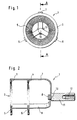
- the figures show a contact element 1, the opening 2 on a not shown tube made of an electrically non-conductive material, preferably glass or glass ceramic, which has a circumferential outer electrical Has conductive coating as an electrode, is mountable.
- a contact element 1 the opening 2 on a not shown tube made of an electrically non-conductive material, preferably glass or glass ceramic, which has a circumferential outer electrical Has conductive coating as an electrode, is mountable.
- Such Tube is the subject of DE 195 11 001 A1 cited at the beginning, so that this point can be referred to.
- a plastic can also be used appropriate hardness can be used.
- the contact element 1 has two axially spaced contact rings 3, 4, which both peripherally circumferential, arranged in a ring Have contact brushes 5, 6.
- the contact rings 3, 4 are via three axially extending webs 7, 8 and 9 mechanically and electrically connected to each other.
- the webs are on one joint connection point 10 and there e.g. by means of spot welding interconnected, as well as the webs 7, 8, 9 preferably by Spot welding with the contact rings 3, 4 are connected.
- the diameter of the bristles of the contact brushes 5, 6 in the brush rings 5, 6 is preferably 0.02 mm.
- the individual bristles then adapt due to their small diameter and their natural springy Properties of the rough surface of the tube electrode and ensure a safe contact.
- a threaded bolt 11 is located at the common connection point 10 welded, the internal thread 12 of the screw connection of a conventional Staff security corresponds.
- This can be used, for example, in one Tube ozonizer, in which several tubes with the invention Contact element are interconnected, secure each individual tube, see above that other tubes will not be affected in the event of a fault.
- the contact element according to the invention allows adaptation of a Security element in the KV area.
- a tube that with the invention Contact element 1 is provided, application in a tube ozonizer.
- the outer coated electrode of the tube is covered with a Dielectric provided with a discharge gap between the dielectric and a second outer coaxial electrode.
- a Dielectric provided with a discharge gap between the dielectric and a second outer coaxial electrode.
Landscapes
- Chemical & Material Sciences (AREA)
- Organic Chemistry (AREA)
- Inorganic Chemistry (AREA)
- Oxygen, Ozone, And Oxides In General (AREA)
Description
- hohe Ozonbeständigkeit
- Hochspannungsfestigkeit
- kleiner Übergangswiderstand Kontakt/Glasrohr trotz hoher Rauhigkeit der leitfähigen Glasbeschichtung
- Kontaktierung über den gesamten Zylinderumfang im Kontaktbereich
- fester mechanischer Sitz auf dem Glasrohr
- minimale äußere Abmessungen
- Sicherstellung, daß bei der Kontaktmontage weder Beschichtung noch Glas beschädigt werden können
- möglichst geringer Montage-/Demontageaufwand
- Fig. 1
- eine Draufsicht auf die Öffnung des erfindungsgemäßen Kontaktelementes, und
- Fig. 2
- einen Längsschnitt durch das Kontaktelement, genommen entlang der Schnittlinie A-A in Fig. 1.
Claims (6)
- Montierbares Kontaktelement (1) für eine Röhre aus einem elektrisch nichtleitenden Werkstoff, die eine umlaufende äußere elektrisch leitende Beschichtung als Elektrode aufweist, dadurch gekennzeichnet, daß zwei axial beabstandet angeordnete Kontaktringe (3, 4) mit elektrisch leitenden und mechanisch stabilisierenden Verbindungselementen zu der Elektrode vorgesehen sind, die bei mindestens einem Kontaktring (3, 4) als peripher umlaufende Kontaktbürsten (5, 6) ausgebildet sind, und daß die Kontaktringe (3, 4) über axial verlaufende Stege (7, 8, 9), die auf einen gemeinsamen Anschlußpunkt (10) geführt sind, untereinander mechanisch und elektrisch leitend verbunden sind.
- Kontaktelement nach Anspruch 1, dadurch gekennzeichnet, daß beide Kontaktringe (3, 4) mit peripher umlaufenden Kontaktbürsten (5, 6) versehen sind.
- Kontaktelement nach Anspruch 1 oder 2, dadurch gekennzeichnet, daß die Kontaktringe (3, 4) mit den Kontaktbürsten (5, 6) sowie die Stege (7, 8, 9) aus Stahl mit der Bezeichnung ST 1.4571 bestehen.
- Kontaktelement nach einem der Ansprüche 1 bis 3, dadurch gekennzeichnet, daß die Borsten der Kontaktbürsten (5, 6) einen Durchmesser in der Größenordnung von 0,02 mm besitzen.
- Kontaktelement nach einem der Ansprüche 1 bis 4, dadurch gekennzeichnet, daß drei jeweils um 120° peripher versetzte Stege (7, 8, 9) vorgesehen sind.
- Kontaktelement nach einem der Ansprüche 1 bis 5, dadurch gekennzeichnet, daß die Röhre eine zylindrische Glas- oder Glaskeramikröhre eines Röhren-Ozonisators ist, die von einem Dielektrikum und einem Entladungsspalt zwischen diesem und einer zweiten äußeren koaxialen Elektrode umgeben ist.
Applications Claiming Priority (3)
| Application Number | Priority Date | Filing Date | Title |
|---|---|---|---|
| DE19725524A DE19725524C1 (de) | 1997-06-17 | 1997-06-17 | Montierbares Kontaktelement für eine Röhre mit einer äußeren Elektrode |
| DE19725524 | 1997-06-17 | ||
| PCT/EP1998/003080 WO1998057885A1 (de) | 1997-06-17 | 1998-05-26 | Montierbares kontaktelement für eine röhre mit einer äusseren elektrode |
Publications (2)
| Publication Number | Publication Date |
|---|---|
| EP0991588A1 EP0991588A1 (de) | 2000-04-12 |
| EP0991588B1 true EP0991588B1 (de) | 2001-03-07 |
Family
ID=7832696
Family Applications (1)
| Application Number | Title | Priority Date | Filing Date |
|---|---|---|---|
| EP98929375A Expired - Lifetime EP0991588B1 (de) | 1997-06-17 | 1998-05-26 | Montierbares kontaktelement für eine röhre mit einer äusseren elektrode |
Country Status (4)
| Country | Link |
|---|---|
| US (1) | US6277336B1 (de) |
| EP (1) | EP0991588B1 (de) |
| DE (2) | DE19725524C1 (de) |
| WO (1) | WO1998057885A1 (de) |
Families Citing this family (4)
| Publication number | Priority date | Publication date | Assignee | Title |
|---|---|---|---|---|
| US7029637B2 (en) | 2003-01-09 | 2006-04-18 | H203, Inc. | Apparatus for ozone production, employing line and grooved electrodes |
| US8199453B2 (en) * | 2003-03-17 | 2012-06-12 | Illinois Tool Works Inc. | Shaft current control brush ring assembly |
| US7252750B2 (en) * | 2003-09-16 | 2007-08-07 | Taiwan Semiconductor Manufacturing Co., Ltd. | Dual contact ring and method for metal ECP process |
| US20070278093A1 (en) * | 2006-06-02 | 2007-12-06 | Barnard Michael P | Electrical conductive contact ring for electroplating or electrodeposition |
Family Cites Families (14)
| Publication number | Priority date | Publication date | Assignee | Title |
|---|---|---|---|---|
| US4035657A (en) * | 1975-12-24 | 1977-07-12 | Murray J. Guy | Ozone generator |
| DE2606731C3 (de) * | 1976-02-19 | 1978-09-21 | Arthur Bachenbuelach Gneupel (Schweiz) | Röhrenförmiger Ozonerzeuger |
| JPS52111488A (en) * | 1976-03-16 | 1977-09-19 | Toshiba Corp | Ozonizer |
| CH642606A5 (de) * | 1980-01-14 | 1984-04-30 | Bbc Brown Boveri & Cie | Ozonisator. |
| US4650573A (en) * | 1985-01-14 | 1987-03-17 | Nathanson Roger T | Ozone generator water treatment |
| JPS61186206A (ja) * | 1985-02-13 | 1986-08-19 | Mitsubishi Electric Corp | オゾン発生装置 |
| DE3870803D1 (de) * | 1987-10-27 | 1992-06-11 | Ozonia Ag | Ozonerzeuger. |
| US4877588A (en) * | 1988-06-17 | 1989-10-31 | Trineos | Method and apparatus for generating ozone by corona discharge |
| PL157693B1 (en) * | 1988-07-04 | 1992-06-30 | Inst Mech Precyz | Ozone generator |
| US5002739A (en) * | 1990-09-11 | 1991-03-26 | Trineos | Ozone cell with cooling bellows |
| DE4208376A1 (de) * | 1992-03-16 | 1993-09-23 | Asea Brown Boveri | Hochleistungsstrahler |
| DE4235743A1 (de) * | 1992-10-23 | 1994-04-28 | Heraeus Noblelight Gmbh | Hochleistungsstrahler |
| DE19511001A1 (de) * | 1995-03-25 | 1996-10-10 | Euroflamm Gmbh | Ozonisator und Verfahren zur Herstellung eines solchen |
| DE19543342A1 (de) * | 1995-11-22 | 1997-05-28 | Heraeus Noblelight Gmbh | Verfahren und Strahlungsanordnung zur Erzeugung von UV-Strahlen zur Körperbestrahlung sowie Verwendung |
-
1997
- 1997-06-17 DE DE19725524A patent/DE19725524C1/de not_active Expired - Fee Related
-
1998
- 1998-05-26 US US09/445,877 patent/US6277336B1/en not_active Expired - Fee Related
- 1998-05-26 DE DE59800513T patent/DE59800513D1/de not_active Expired - Fee Related
- 1998-05-26 EP EP98929375A patent/EP0991588B1/de not_active Expired - Lifetime
- 1998-05-26 WO PCT/EP1998/003080 patent/WO1998057885A1/de not_active Ceased
Also Published As
| Publication number | Publication date |
|---|---|
| US6277336B1 (en) | 2001-08-21 |
| DE59800513D1 (de) | 2001-04-12 |
| DE19725524C1 (de) | 1998-10-01 |
| WO1998057885A1 (de) | 1998-12-23 |
| EP0991588A1 (de) | 2000-04-12 |
Similar Documents
| Publication | Publication Date | Title |
|---|---|---|
| DE2708596A1 (de) | Metallgekapselte hochspannungsanlage | |
| DE2346174A1 (de) | Ueberspannungsableiter | |
| DE112005003138B4 (de) | Multikanal-Entlader mit multiplen Intervallen und gepulster Hochleistungsgenerator | |
| DE3835921C2 (de) | Überspannungsableiter mit Luftfunkenstrecke | |
| DE3101354C2 (de) | Funkenstrecke für die Begrenzung von Überspannungen | |
| DE19725524C1 (de) | Montierbares Kontaktelement für eine Röhre mit einer äußeren Elektrode | |
| DE19641385B4 (de) | Gasgefüllter Überspannungsableiter | |
| DE3118137C2 (de) | Gasentladungs-Überspannungsableiter mit parallel geschalteter Luftfunkenstrecke | |
| DE102020212404A1 (de) | Feldsondenkombination zur Verwendung bei Mittel- und Hochspannungen | |
| DE19547120A1 (de) | Elektrode | |
| DE3214487C2 (de) | ||
| DE19605979C2 (de) | Strom-tragfähiges Verbindungselement für Rohrleitungen einer gasisolierten Schaltanlage | |
| DE2849287A1 (de) | Hochspannungsvakuumschalter | |
| DE4016997C1 (de) | ||
| EP1249850B1 (de) | Isoliergehäuse, insbesondere Gehäuse einer Schaltröhre eines Vakuumschalters, mit einer Halterung zur Positionierung einer Steuerelektrode | |
| EP0715894A1 (de) | Elektrostatische Filtereinrichtung | |
| DE2602569C2 (de) | Überspannungs-Knopfableiter | |
| DE2814994C3 (de) | Brennelektrode für einen Lichtbogenschutzring | |
| DE102017102370A1 (de) | Verbindungsmuffe | |
| DE19629344C2 (de) | Gleitfunkenzündkerze zum Zünden eines Brennstoff-Luft-Gemisches | |
| EP4341977B1 (de) | Vakuumschalteinheit und vakuumschalter | |
| DE102011108858A1 (de) | Elektrischer Drei-Elektroden-Überspannungsableiter | |
| DE3630027A1 (de) | Gekapselte, druckgasisolierte hochspannungsschaltanlage | |
| DE29615185U1 (de) | Hochspannungseinrichtung mit einem Überspannungsableiter | |
| DE3504189A1 (de) | Schutzentladevorrichtung fuer einen kondensator in einem stosswellengenerator |
Legal Events
| Date | Code | Title | Description |
|---|---|---|---|
| PUAI | Public reference made under article 153(3) epc to a published international application that has entered the european phase |
Free format text: ORIGINAL CODE: 0009012 |
|
| 17P | Request for examination filed |
Effective date: 19991029 |
|
| AK | Designated contracting states |
Kind code of ref document: A1 Designated state(s): CH DE FR LI |
|
| GRAG | Despatch of communication of intention to grant |
Free format text: ORIGINAL CODE: EPIDOS AGRA |
|
| GRAG | Despatch of communication of intention to grant |
Free format text: ORIGINAL CODE: EPIDOS AGRA |
|
| GRAH | Despatch of communication of intention to grant a patent |
Free format text: ORIGINAL CODE: EPIDOS IGRA |
|
| 17Q | First examination report despatched |
Effective date: 20000719 |
|
| GRAH | Despatch of communication of intention to grant a patent |
Free format text: ORIGINAL CODE: EPIDOS IGRA |
|
| GRAA | (expected) grant |
Free format text: ORIGINAL CODE: 0009210 |
|
| AK | Designated contracting states |
Kind code of ref document: B1 Designated state(s): CH DE FR LI |
|
| REG | Reference to a national code |
Ref country code: CH Ref legal event code: EP |
|
| REF | Corresponds to: |
Ref document number: 59800513 Country of ref document: DE Date of ref document: 20010412 |
|
| ET | Fr: translation filed | ||
| PLBE | No opposition filed within time limit |
Free format text: ORIGINAL CODE: 0009261 |
|
| STAA | Information on the status of an ep patent application or granted ep patent |
Free format text: STATUS: NO OPPOSITION FILED WITHIN TIME LIMIT |
|
| 26N | No opposition filed | ||
| REG | Reference to a national code |
Ref country code: CH Ref legal event code: PUE Owner name: SCHOTT GLAS GMBH Free format text: SCHOTT-GERAETE GMBH#IM LANGGEWANN 5#65719 HOFHEIM A. TS. (DE) -TRANSFER TO- SCHOTT GLAS GMBH#HATTENBERGSTRASSE 10#55122 MAINZ (DE) |
|
| REG | Reference to a national code |
Ref country code: FR Ref legal event code: TP |
|
| REG | Reference to a national code |
Ref country code: FR Ref legal event code: RM |
|
| REG | Reference to a national code |
Ref country code: CH Ref legal event code: PUE Owner name: SCHOTT AG Free format text: SCHOTT GLAS#HATTENBERGSTRASSE 10#55122 MAINZ (DE) -TRANSFER TO- SCHOTT AG#HATTENBERGSTRASSE 10#55122 MAINZ (DE) |
|
| REG | Reference to a national code |
Ref country code: FR Ref legal event code: TP |
|
| PGFP | Annual fee paid to national office [announced via postgrant information from national office to epo] |
Ref country code: DE Payment date: 20080523 Year of fee payment: 11 Ref country code: CH Payment date: 20080515 Year of fee payment: 11 |
|
| REG | Reference to a national code |
Ref country code: CH Ref legal event code: PL |
|
| PG25 | Lapsed in a contracting state [announced via postgrant information from national office to epo] |
Ref country code: LI Free format text: LAPSE BECAUSE OF NON-PAYMENT OF DUE FEES Effective date: 20090531 Ref country code: CH Free format text: LAPSE BECAUSE OF NON-PAYMENT OF DUE FEES Effective date: 20090531 |
|
| REG | Reference to a national code |
Ref country code: FR Ref legal event code: ST Effective date: 20100129 |
|
| PG25 | Lapsed in a contracting state [announced via postgrant information from national office to epo] |
Ref country code: FR Free format text: LAPSE BECAUSE OF NON-PAYMENT OF DUE FEES Effective date: 20090602 |
|
| PGFP | Annual fee paid to national office [announced via postgrant information from national office to epo] |
Ref country code: FR Payment date: 20080526 Year of fee payment: 11 |
|
| PG25 | Lapsed in a contracting state [announced via postgrant information from national office to epo] |
Ref country code: DE Free format text: LAPSE BECAUSE OF NON-PAYMENT OF DUE FEES Effective date: 20091201 |