EP0991201A2 - Emetteur à AMRC capable de reduire la puissance d'émission - Google Patents
Emetteur à AMRC capable de reduire la puissance d'émission Download PDFInfo
- Publication number
- EP0991201A2 EP0991201A2 EP99119201A EP99119201A EP0991201A2 EP 0991201 A2 EP0991201 A2 EP 0991201A2 EP 99119201 A EP99119201 A EP 99119201A EP 99119201 A EP99119201 A EP 99119201A EP 0991201 A2 EP0991201 A2 EP 0991201A2
- Authority
- EP
- European Patent Office
- Prior art keywords
- dummy symbol
- signal
- peak
- symbol
- input data
- Prior art date
- Legal status (The legal status is an assumption and is not a legal conclusion. Google has not performed a legal analysis and makes no representation as to the accuracy of the status listed.)
- Withdrawn
Links
Images

Classifications
-
- H—ELECTRICITY
- H04—ELECTRIC COMMUNICATION TECHNIQUE
- H04B—TRANSMISSION
- H04B1/00—Details of transmission systems, not covered by a single one of groups H04B3/00 - H04B13/00; Details of transmission systems not characterised by the medium used for transmission
- H04B1/02—Transmitters
-
- H—ELECTRICITY
- H04—ELECTRIC COMMUNICATION TECHNIQUE
- H04J—MULTIPLEX COMMUNICATION
- H04J13/00—Code division multiplex systems
- H04J13/0007—Code type
- H04J13/004—Orthogonal
- H04J13/0048—Walsh
-
- H—ELECTRICITY
- H04—ELECTRIC COMMUNICATION TECHNIQUE
- H04B—TRANSMISSION
- H04B1/00—Details of transmission systems, not covered by a single one of groups H04B3/00 - H04B13/00; Details of transmission systems not characterised by the medium used for transmission
- H04B1/69—Spread spectrum techniques
- H04B1/707—Spread spectrum techniques using direct sequence modulation
-
- H—ELECTRICITY
- H04—ELECTRIC COMMUNICATION TECHNIQUE
- H04B—TRANSMISSION
- H04B2201/00—Indexing scheme relating to details of transmission systems not covered by a single group of H04B3/00 - H04B13/00
- H04B2201/69—Orthogonal indexing scheme relating to spread spectrum techniques in general
- H04B2201/707—Orthogonal indexing scheme relating to spread spectrum techniques in general relating to direct sequence modulation
- H04B2201/70706—Orthogonal indexing scheme relating to spread spectrum techniques in general relating to direct sequence modulation with means for reducing the peak-to-average power ratio
Definitions
- This invention relates to a transmitter for use in CDMA (Code Division Multiple Access), which will be called a CDMA transmitter.
- CDMA Code Division Multiple Access
- a base station has a CDMA transmitter which is operable in response to a plurality of input data signals.
- the CDMA transmitter spreads the input data signals by the use of short codes, such as Walsh codes, and long codes, such as pseudo random sequences, and thereafter transmits a transmission signal through a power amplifier downwards (namely, from the base station to mobile stations).
- the input data signals are individually subjected to spread spectrum modulation and are synthesized into a synthesized signal.
- the synthesized signal is varied in electric power over a very wide range, depending upon a peak value of each input data signal.
- a linear amplifier is used as the power amplifier to amplify the synthesized signal into the transmission signal.
- the power amplifier should have high power so as to linearly amplify the synthesized signal varied over the wide range and is therefore inevitably very expensive.
- a limiter is arrange prior to the power amplifier to limit an amplitude of the synthesized signal.
- such arrangement of the limiter deteriorates a transmission characteristic of the CDMA transmitter because the limiter itself is a nonlinear element.
- a CDMA transmitter to which this invention is applicable is operable in response to a plurality of input data signals to transmit a transmission signal, by subjecting the input data signals to symbol modulation, spread spectrum modulation, synthesizing, and amplification.
- the CDMA transmitter comprises a peak detector for detecting peak electric power of the input data signals synthesized to produce a peak power signal representative of the peak electric power, a dummy symbol generator, supplied with the peak power signal, for generating a dummy symbol such that the peak electric power is decreased, and a calculation circuit for calculating the synthesized input data signals and the dummy symbol to produce the transmission signal.
- the peak detector is supplied with each symbol of the input data signals which are subjected to the symbol modulation and the spread spectrum modulation and which are added by an adder.
- the peak detector detects the peak electric power of each symbol.
- the CDMA transmitter further may comprise a delay circuit which has a delay time delaying each synthesized input data signals by a single symbol time and which produces a delayed synthesized data signal.
- the calculation circuit comprises a subtractor for subtracting the dummy symbol from the delayed synthesized data signal.
- the above-mentioned dummy symbol generator comprises a comparator for comparing the peak power signal with a predetermined power level to detect whether or not the peak power signal exceeds the predetermined power level and a generating circuit for generating the dummy symbol when the peak power signal exceeds the predetermined power level.
- the dummy symbol generator generates the dummy symbol which is orthogonal to the synthesized input data signals and which is generated by the use of a code sequence which is unused in the synthesized input data signals.
- the dummy symbol is generated by the dummy symbol generator by the use of Walsh codes.
- the dummy symbol generator comprises a plurality of code generators for producing a plurality of codes different from one another, a weight calculator for calculating weight coefficients given to the codes, with reference to the peak power signal detected by the peak detector, a multiplier for multiplying the plurality of the codes by the weight coefficients to produce multiplied codes, and an adder circuit for summing up the multiplied codes to produce the dummy symbol.
- a CDMA transmitter may comprise a power adjustment circuit for adjusting transmission electric power with reference to the peak power signal.
- a CDMA transmitter is operable in response to a plurality of input data signals to produce a transmission signal and comprises a spread section for spectrum spreading the input data signals by using a plurality of predetermined spread codes to produce a synthesized signal, a dummy symbol generator for generating a dummy symbol which is subjected to spread spectrum modulation by the use of spread codes which are different from the predetermined spread codes, and a combining section for combining the synthesized signal with the dummy symbol.
- the illustrated CDMA transmitter has a plurality of input terminals IN1 to INn, n in number, where n is a positive integer.
- the input terminals IN1 to INn will be called first through n-th input terminals and are given from first through n-th users (not shown) first through n-th input data signals D1 to Dn representative of first trough n-th transmission data, respectively.
- the first through the n-th input data signals D1 to Dn are sent to first through n-th data modulators DM1 to DMn, respectively, to be subjected to data modulation.
- Each of the first through the n-th input data signals D1 and Dn is modulated in each data modulator DM1 to DMn by a carrier into a modulated data signal in a base-band to be sent to each of first through n-th spread spectrum modulators SM1 to SMn.
- the data modulation may be, for example, QPSK.
- the first through the n-th spread spectrum modulators SM1 to SMn are operated to carry out spread spectrum modulation of the modulated data signals by the use of spread codes, such as Walsh codes, and/or pseudo random codes, (namely, short codes and/or long codes) and to produce first through n-th spectrum spread signals, respectively.
- the first through the n-th spectrum spread signals are given to an adder AD to be summed up and to be produced as a summed signal.
- the summed signal is limited by a limiter LM and is thereafter sent to a power amplifier, namely, a transmission amplifier AP to be transmitted as a transmission signal through an antenna.
- the power amplifier is usually formed by a linear amplifier.
- the transmission signal has peak electric power as transmission power on transmission from the illustrated CDMA transmitter. For example, let each of the first through the n-th spectrum spread signals be transmitted with 1 Watt for each user and the number of the users be equal to ten in number. In this case, average electric power for ten users is equal to ten Watts. However, peak electric power must become ten times the average electric power and is therefore equal to 100 Watts.
- the limiter LM limits peak electric power of the summed signal at a limit electric power level which corresponds to a saturation output level of the power amplifier AP.
- the electric power which exceeds the limit electric level is forcibly and nonlinearly cut out by the limiter LM.
- Such nonlinear operation by the limiter LM inevitably degrades a signal transmission characteristic in the conventional CDMA transmitter.
- the conventional CDMA transmitter should have the power amplifier AP of very high power so as to linearly amplify an output signal given to the power amplifier AP.
- Such a power amplifier AP of high power consumes large electric power.
- a cost of a whole of the CDMA transmitter is determined by the cost of the power amplifier AP.
- the first through the n-th spread spectrum modulators SM1 to SMn carry out the spread spectrum modulation by the use of the Walsh codes of 32 ksps (kilo symbol per second) and are assumed to be smaller in number than the Walsh codes.
- the Walsh codes 32 ksps (kilo symbol per second) and are assumed to be smaller in number than the Walsh codes.
- unused ones of the Walsh codes are left in the CDMA transmitter.
- any other short and/or long codes may be assigned to the first through the n-th spread spectrum modulators SM1 to SMn, with unused codes left in such short and/or long codes.
- the adder AD produces the summed signal which is depicted by T(i) in Fig. 2 and which may be called a synthesized signal.
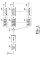
- the CDMA transmitter further comprises a symbol delay unit SD, a peak detector PD, a dummy symbol generator DM, a level adjustment calculator LA, a subtractor SU, and a multiplier MU. All of the enumerated units are located between the adder AD and the limiter LM.
- the summed or synthesized signal T(i) is formed by a sequence of symbols, as readily understood from the above, and given to the symbol delay unit SD and the peak detector PD.
- the synthesized signal T(i) is delayed by the symbol delay unit SD by a single symbol time to be sent to the subtractor SU as a delayed signal.
- the peak detector PD detects a peak value (a maximum value of electric power) at every symbol of the synthesized signal T(i).
- the peak value detected by the peak detector PD is delivered to the dummy symbol generator DM on one hand and to the level adjustment calculator LA on the other hand.
- the dummy symbol generator DM generates a dummy symbol with reference to the peak value in a manner to be described later in detail. At any rate, the dummy symbol serves to reduce or cancel the peak value of each symbol of the synthesized signal T(i) and is sent to the subtractor SU which is supplied with the synthesized signal T(i).
- the subtractor SU subtracts the peak value from the synthesized signal at every symbol to produce a peak suppressed or canceled signal.
- the level adjustment calculator LA calculates a power correction value (level adjustment value) from the peak value to produce a power correction signal (or a level adjustment signal) representative of the power correction value (or the level adjustment value).
- the multiplier MU multiplies the peak suppressed signal by the power correction signal to produce a product signal representative of a product of the peak suppressed signal and the power correction signal.
- the product signal is sent through the limiter LM to the power amplifier AP and is linearly amplified by the power amplifier AP into the transmission signal.
- the dummy symbol generator DM judges whether or not the peak value detected by the peak detector PD is greater than the maximum acceptable input power (Pin) of the power amplifier AP. As a result, when it is judged that the peak value is greater than the maximum acceptable input power P(in), the dummy symbol generator DM generates the dummy symbol S(i) which can cancel the peak value of each symbol of the synthesized signal T(i). Such a dummy symbol S(i) is subtracted from each symbol of the synthesized signal delayed by the symbol delay unit SD by the subtractor SU. In consequence, the peak suppressed signal is produced by the subtractor SU and is sent to the multiplier MU.
- Pin maximum acceptable input power
- a combination of the data modulators DM1 to DMn, the spread spectrum modulators SM1 to SMn, and the adder AD may be referred to as a spectrum spread section while a combination of the peak detector PD and the dummy symbol generator DM may be referred to as a dummy symbol section.
- the remaining elements may be collectively called a combination section for combining the synthesized signal with the dummy symbol.
- the dummy symbol generator DM generates the dummy symbol S(i) which is orthogonal to the synthesized signal, namely, each of transmission symbols and which may be formed by the Walsh codes.
- the Walsh codes which are used for the dummy symbol are selected from the Walsh codes which are not used to spread the first through the n-th input data signals D1 to Dn in the first through the n-th spread spectrum modulators SM1 to SMn.
- the Walsh codes for the dummy symbol S(i) are unused for transmission of the first through the n-th input data signals D1 to Dn and may be called unused codes.
- j is not smaller than zero and is smaller than K; and i, not smaller than zero and is smaller than L.
- S(i) is representative of the dummy symbol; L, a symbol length; K, the number assigned to the Walsh codes; W(i,j), a value of an i-th symbol in the j-th one of the Walsh codes; and Aj, a coefficient of an amplitude.
- the peak value is spectrum spread by the use of the unused Walsh codes.
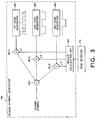
- the dummy code generator DM has first through third code generators M1 to M3 which may be formed by code memories to produce first through third unused Walsh codes W1 to W3 which are not used for the first through the n-th input data signals D1 to Dn.
- the first through the third unused Walsh codes W1 to W3 may have waveforms as exemplified under each code generator M1 to M3 in Fig. 3.
- the dummy symbol generator DM illustrated in Fig. 3 has a weight calculation circuit WC which is supplied with the peak value from the peak detector PD. Supplied with the peak value, the weight calculation circuit WC calculates first, second, and third weight coefficients ⁇ 1, ⁇ 2,and ⁇ 3 determined for the first through the third unused Walsh codes W1 to W3 on the basis of the peak value, respectively. The first through the third weight coefficients ⁇ 1, ⁇ 2,and ⁇ 3 are sent to first, second, and third multipliers MU1, MU2, and MU3 as first through third weight coefficient signals, respectively.
- the above-mentioned calculation may be executed only when the peak value exceeds the acceptable maximum input power Pin of the power amplifier AP.
- the weight calculation circuit WC may have a comparator for comparing the peak value with the acceptable maximum input power Pin.
- the weight calculation circuit WC may be structured so that the weight coefficients ⁇ 1, ⁇ 2,and ⁇ 3 may take zero as long as the peak value does not exceed the acceptable maximum input power Pin.
- the first through third weight coefficients ⁇ 1, ⁇ 2,and ⁇ 3 are given to the first through the third multipliers MU1 to MU3 which are supplied with the first through the third unused Walsh codes W1 to W3, respectively.
- the first through the third multipliers MU1 to MU3 multiply the first through the third unused Walsh codes W1 to W3 by the first through the third weight coefficients ⁇ 1, ⁇ 2,and ⁇ 3 to supply first through third multiplied Walsh codes to an adder AD1.
- the first through the third multiplied Walsh codes are summed up by the adder AD1 to obtain a sum signal.
- the sum signal is sent to the subtractor SU (Fig. 2) as the dummy symbol S(i).
- a reduction rate of each code with respect to each input data signal D1 to Dn is assumed to be represented by ⁇ .
- the dummy symbol S(i) which is calculated in the above-mentioned manner is delivered to the subtractor SU shown in Fig. 2 to subtract the dummy symbol S(i) from the delayed synthesized signal T(i) and to obtain the peak suppressed signal which will be represented by T'(i) hereinafter.
- T'(i) T(i) - S(i).
- the peak value of the delayed synthesized signal T(i) may be decreased by the dummy symbol S(i). This means that addition of the dummy symbol S(i) to the delayed synthesized signal T(i) may be executed, if a reduction is possible about the peak value of the delayed synthesized signal T(i).
- a distribution of the electric power namely, the average electric power is varied in the peak suppressed signal by modifying the delayed synthesized signal T(i) by the dummy symbol S(i) in the above-mentioned manner. Taking this into account, compensation of the electric power is carried out in accordance with a predetermined algorithm. To this end, the level adjustment calculator LA calculates a power adjustment value ⁇ which may be called a power correction value.
- the power adjustment value ⁇ is determined so that the following formula is satisfied: Pin ⁇ ⁇ x Pmax (where 0 ⁇ ⁇ ⁇ 1).
- the power adjustment value ⁇ is determined in consideration of the acceptable maximum input power Pin of the power amplifier AP.
- the power adjusted signal T''(i) is sent to the limiter LM which limits the amplitude of the power adjusted signal T''(i) at a predetermined limit level which may be equal to Pin.
- the power adjusted signal T''(i) may exceed Pin because the power adjusted signal T''(i) higher than Pin is limited by the limiter LM.
- the power adjustment value ⁇ is determined in accordance with an algorithm which can avoid both degradation of a transmission characteristic due to the limiter LM and deterioration which occurs due to compensation or modification of the input data signals.
- Equation (2) it is readily understood that, as the power adjustment value ⁇ becomes large, a ratio of the second component of the right-hand side of Equation (2) to Pout becomes relatively small. In other words, an influence of the dummy symbol becomes small. This is effective to lighten a load imposed on the power amplifier AP.
- the symbol delay unit SD is used to delay the synthesized signal by one symbol.
- a symbol delay unit may be removed when high speed elements are used. This structure serves to shorten a processing time and a delay time.
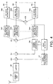
- a CDMA transmitter according to a modification of this invention comprises similar parts designated by like reference symbols and dispenses with the symbol delay unit SD illustrated in Fig. 2.
- the first through the n-th input data signals D1 to Dn are subjected to data modulation, such as QPSK, to be sent as first through n-th data modulated signals (namely, symbol modulated signals) to the first through the n-th spread spectrum modulators SM1 to SMn on one hand and to an additional adder AD2 on the other hand.
- data modulation such as QPSK
- the first through the n-th data modulated signals are delivered to the first through the n-th spread spectrum modulators SM1 to SMn to be processed by the first through the n-th spread spectrum modulators SM1 to SMn in a manner similar to that illustrated with reference to Fig. 2.
- the first through the n-th spectrum spread signals are sent to the adder AD to be produced as the synthesized signal T(i).
- the additional adder AD2 sums up the first through the n-th data modulated signals to supply a summed signal to the peak detector PD.
- the peak detector PD detects a peak value from the summed signal.
- the peak value detected is sent to the dummy symbol generator DM and the level adjustment calculator LA.
- the dummy symbol generator DM generates ,on the basis of the peak value, the dummy symbol which can cancel or decrease the peak value and supplies the dummy symbol to the subtractor SU.
- the subtractor SU subtracts the dummy symbol from the synthesized signal sent from the adder AD to produce a peak suppressed signal, as mentioned in conjunction with Fig. 2.
- the level adjustment calculator LA calculates the power adjustment value from the peak value detected by the peak detector PD.
- the power adjustment value is multiplied by the multiplier MU by the peak suppressed signal to be sent as the transmission signal through the limiter LM and the power amplifier AP to the antenna.
- the dummy symbol is used to modify the peak value of the synthesized signal and to reduce the electric power of the power amplifier AP.
- This structure is effective to decrease the peak electric power and to alleviate requirements for the power amplifier. For example, when the power amplifier AP can reduce the transmission power by 3 dB, the cost of the power amplifier AP can be reduced to one fourth and becomes very inexpensive. This shows that the power amplifier AP may be small in size and in electric power.
- the electric power of the peak suppressed signal is adjusted by the level adjustment value prior to the supply to the power amplifier. This structure can compensate a variation of the electric power which might occur due to addition of the dummy symbol and can avoid a variation of the average electric power.
- the CDMA transmitter transmits the transmission signal which carries not only the input data signals but also the dummy signal.
- a dummy signal is not demodulated by any receivers because the dummy signal is spread by the use of the spread codes which are not used for transmission, as mentioned before.
- the transmission signal which includes the dummy symbol can be received by usual CDMA receivers regardless of inclusion of the dummy signals.
- the dummy symbol may be superposed on the synthesized signal for another purpose different from the reduction of the peak value of the synthesized signal.
Landscapes
- Engineering & Computer Science (AREA)
- Computer Networks & Wireless Communication (AREA)
- Signal Processing (AREA)
- Transmitters (AREA)
- Mobile Radio Communication Systems (AREA)
- Compression, Expansion, Code Conversion, And Decoders (AREA)
Applications Claiming Priority (2)
| Application Number | Priority Date | Filing Date | Title |
|---|---|---|---|
| JP27397198 | 1998-09-28 | ||
| JP27397198A JP2988522B1 (ja) | 1998-09-28 | 1998-09-28 | Cdma送信機 |
Publications (2)
| Publication Number | Publication Date |
|---|---|
| EP0991201A2 true EP0991201A2 (fr) | 2000-04-05 |
| EP0991201A3 EP0991201A3 (fr) | 2003-01-29 |
Family
ID=17535138
Family Applications (1)
| Application Number | Title | Priority Date | Filing Date |
|---|---|---|---|
| EP19990119201 Withdrawn EP0991201A3 (fr) | 1998-09-28 | 1999-09-27 | Emetteur à AMRC capable de reduire la puissance d'émission |
Country Status (6)
| Country | Link |
|---|---|
| US (1) | US6519244B1 (fr) |
| EP (1) | EP0991201A3 (fr) |
| JP (1) | JP2988522B1 (fr) |
| KR (1) | KR100319997B1 (fr) |
| CN (1) | CN1249582A (fr) |
| BR (1) | BR9907469A (fr) |
Cited By (3)
| Publication number | Priority date | Publication date | Assignee | Title |
|---|---|---|---|---|
| WO2002009373A2 (fr) * | 2000-07-21 | 2002-01-31 | Pmc-Sierra, Ltd. | Systemes et procedes de reduction de pics en niveaux de signal moyen d'oscillogrammes a ondes porteuses multiples et uniques a capacite multiple |
| US6519244B1 (en) * | 1998-09-28 | 2003-02-11 | Nec Corporation | CDMA transmitter capable of reducing transmission power |
| EP2074703A1 (fr) * | 2006-06-22 | 2009-07-01 | Telefonaktiebolaget LM Ericsson (PUBL) | Attribution de puissance en cas d'envoi simultané de messages multiples |
Families Citing this family (20)
| Publication number | Priority date | Publication date | Assignee | Title |
|---|---|---|---|---|
| JP3715141B2 (ja) * | 1999-07-13 | 2005-11-09 | 松下電器産業株式会社 | 通信端末装置 |
| JP3478496B2 (ja) | 2000-11-24 | 2003-12-15 | 松下電器産業株式会社 | 送信電力制御方法及びその装置並びに通信装置 |
| US6826201B2 (en) * | 2000-12-19 | 2004-11-30 | Nortel Networks Limited | Multiplexing SONET /SDH data streams using independent encoding schemes |
| JP2003258768A (ja) | 2002-02-27 | 2003-09-12 | Fujitsu Ltd | 拡散信号多重化回路 |
| US6888393B2 (en) | 2002-09-04 | 2005-05-03 | Hitachi Kokusai Electric, Inc. | Amplitude limiting apparatus and multi-carrier signal generating apparatus |
| CN100483967C (zh) * | 2002-12-31 | 2009-04-29 | 中国科学技术大学 | 一种控制峰值功率的发射机和接收机 |
| US7251463B2 (en) * | 2003-06-30 | 2007-07-31 | Crestcom, Inc. | Methods and apparatus for controlling signals |
| US7295816B2 (en) * | 2003-06-30 | 2007-11-13 | Crestcom, Inc. | Methods and apparatus for controlling signals |
| JP4287225B2 (ja) * | 2003-09-18 | 2009-07-01 | 株式会社日立国際電気 | 送信機 |
| KR20040014614A (ko) * | 2004-01-13 | 2004-02-14 | 유흥균 | 코드선택 기법과 코드율이 1인 새로운 프리코딩을이용하여 대역폭 증가가 없는 2진 정진폭 mc-cdma 통신시스템의 설계 방법과 장치구성 |
| JP4469685B2 (ja) | 2004-08-25 | 2010-05-26 | 富士通株式会社 | 出力電力誤差吸収回路及び同回路を有するマルチキャリア送信機 |
| JP4619797B2 (ja) | 2005-01-14 | 2011-01-26 | 富士通株式会社 | 無線通信システム及び無線通信装置 |
| JP2007251341A (ja) * | 2006-03-14 | 2007-09-27 | Hitachi Kokusai Electric Inc | 送信機 |
| US7783260B2 (en) * | 2006-04-27 | 2010-08-24 | Crestcom, Inc. | Method and apparatus for adaptively controlling signals |
| JP4629611B2 (ja) * | 2006-05-17 | 2011-02-09 | ソフトバンクBb株式会社 | ピーク電力低減システム及び方法 |
| US8824574B2 (en) * | 2009-09-11 | 2014-09-02 | Crestcom, Inc. | Transmitting unit that reduces PAPR and method therefor |
| US8185065B2 (en) * | 2009-10-15 | 2012-05-22 | Crestcom, Inc. | Transmitting unit that reduces PAPR using out-of-band distortion and method therefor |
| JP5201158B2 (ja) | 2010-02-24 | 2013-06-05 | 住友電気工業株式会社 | 信号処理回路とこの回路を有する通信装置 |
| US20170155536A1 (en) * | 2015-11-30 | 2017-06-01 | Qualcomm Incorporated | Embedding data based on orthogonal codes |
| US9848342B1 (en) | 2016-07-20 | 2017-12-19 | Ccip, Llc | Excursion compensation in multipath communication systems having performance requirements parameters |
Family Cites Families (4)
| Publication number | Priority date | Publication date | Assignee | Title |
|---|---|---|---|---|
| US5757767A (en) * | 1995-04-18 | 1998-05-26 | Qualcomm Incorporated | Method and apparatus for joint transmission of multiple data signals in spread spectrum communication systems |
| JPH10257017A (ja) * | 1997-03-07 | 1998-09-25 | Sanyo Electric Works Ltd | スライディング相関器及びその同期方法 |
| JP2988522B1 (ja) * | 1998-09-28 | 1999-12-13 | 日本電気株式会社 | Cdma送信機 |
| US6188714B1 (en) * | 1998-12-29 | 2001-02-13 | Texas Instruments Incorporated | Parallel M-sequence generator circuit |
-
1998
- 1998-09-28 JP JP27397198A patent/JP2988522B1/ja not_active Expired - Fee Related
-
1999
- 1999-09-27 EP EP19990119201 patent/EP0991201A3/fr not_active Withdrawn
- 1999-09-28 KR KR1019990041476A patent/KR100319997B1/ko not_active IP Right Cessation
- 1999-09-28 US US09/406,716 patent/US6519244B1/en not_active Expired - Fee Related
- 1999-09-28 CN CN99119768A patent/CN1249582A/zh active Pending
- 1999-09-28 BR BR9907469A patent/BR9907469A/pt not_active IP Right Cessation
Non-Patent Citations (3)
| Title |
|---|
| BRAITHWAITE R N: "NONLINEAR AMPLIFICATION OF CDMA WAVEFORMS: AN ANALYSIS OF POWER AMPLIFIER GAIN ERRORS AND SPECTRAL REGROWTH" VTC'98. 48TH. IEEE VEHICULAR TECHNOLOGY CONFERENCE. OTTAWA, CANADA, MAY 18 - 21, 1998, IEEE VEHICULAR TECHNOLOGY CONFERENCE, NEW YORK, NY: IEEE, US, vol. 3 CONF. 48, 18 May 1998 (1998-05-18), pages 2160-2166, XP000903403 ISBN: 0-7803-4321-2 * |
| VAANANEN O ; VANKKA J ; VIERO T ; HALONEN K : "Reducing the crest factor of a CDMA downlink signal by adding unused channelization codes." IEEE COMMUN. LETT. (USA), IEEE COMMUNICATIONS LETTERS,, vol. 6, no. 10, October 2002 (2002-10), pages 443-445, XP002221161 * |
| WADA T ET AL: "A CONSTANT AMPLITUDE CODING FOR ORTHOGONAL MULTI-CODE CDMA SYSTEMS" IEICE TRANSACTIONS ON FUNDAMENTALS OF ELECTRONICS, COMMUNICATIONS AND COMPUTER SCIENCES, INSTITUTE OF ELECTRONICS INFORMATION AND COMM. ENG. TOKYO, JP, vol. E80-A, no. 12, 1 December 1997 (1997-12-01), pages 2477-2483, XP000768674 ISSN: 0916-8508 * |
Cited By (9)
| Publication number | Priority date | Publication date | Assignee | Title |
|---|---|---|---|---|
| US6519244B1 (en) * | 1998-09-28 | 2003-02-11 | Nec Corporation | CDMA transmitter capable of reducing transmission power |
| WO2002009373A2 (fr) * | 2000-07-21 | 2002-01-31 | Pmc-Sierra, Ltd. | Systemes et procedes de reduction de pics en niveaux de signal moyen d'oscillogrammes a ondes porteuses multiples et uniques a capacite multiple |
| WO2002009373A3 (fr) * | 2000-07-21 | 2002-06-06 | Pmc Sierra Ltd | Systemes et procedes de reduction de pics en niveaux de signal moyen d'oscillogrammes a ondes porteuses multiples et uniques a capacite multiple |
| US7061990B2 (en) | 2000-07-21 | 2006-06-13 | Pmc-Sierra Inc. | Systems and methods for the dynamic range compression of multi-bearer single-carrier and multi-carrier waveforms |
| US7061991B2 (en) | 2000-07-21 | 2006-06-13 | Pmc - Sierra Inc. | Systems and methods for the reduction of peak to average signal levels of multi-bearer single-carrier and multi-carrier waveforms |
| US7409011B2 (en) | 2000-07-21 | 2008-08-05 | Pmc-Sierra, Inc. | Systems and methods for the dynamic range compression of multi-bearer single-carrier and multi-carrier waveforms |
| US7453954B2 (en) | 2000-07-21 | 2008-11-18 | Pmc-Sierra, Inc. | Systems and methods for the reduction of peak to average signal levels of multi-bearer single-carrier and multi-carrier waveforms |
| EP2074703A1 (fr) * | 2006-06-22 | 2009-07-01 | Telefonaktiebolaget LM Ericsson (PUBL) | Attribution de puissance en cas d'envoi simultané de messages multiples |
| EP2074703A4 (fr) * | 2006-06-22 | 2014-06-11 | Unwired Planet Internat Ltd | Attribution de puissance en cas d'envoi simultané de messages multiples |
Also Published As
| Publication number | Publication date |
|---|---|
| CN1249582A (zh) | 2000-04-05 |
| JP2988522B1 (ja) | 1999-12-13 |
| BR9907469A (pt) | 2000-09-12 |
| EP0991201A3 (fr) | 2003-01-29 |
| KR100319997B1 (ko) | 2002-01-10 |
| KR20000023484A (ko) | 2000-04-25 |
| JP2000106548A (ja) | 2000-04-11 |
| US6519244B1 (en) | 2003-02-11 |
Similar Documents
| Publication | Publication Date | Title |
|---|---|---|
| EP0991201A2 (fr) | Emetteur à AMRC capable de reduire la puissance d'émission | |
| RU2156545C2 (ru) | Способ управления действительной мощностью передачи базовой станции в сотовой системе связи и устройство для его осуществления | |
| US6414946B1 (en) | Adaptive downlink transmission power control arbiter | |
| EP0776105B1 (fr) | Demodulateur amrc | |
| KR100262378B1 (ko) | 신호대 간섭 전력비 측정 장치,신호대 간섭 전력비 측정 방법 및cdma 통신 방식 하에서의 송신 전력 제어 방법 | |
| US7103029B1 (en) | Transmitter gain stabilizing apparatus | |
| CA2159971C (fr) | Commande d'alimentation utilisant le taux d'erreur sur les symboles pour les telecommunications mobiles | |
| EP1087541B1 (fr) | Procédé et dispositif de commande de la puissance de transmission vers l'avant dans un système de communication sans fil | |
| CA2278299C (fr) | Appareil d'estimation de voies, recepteur et emetteur-recepteur a acces multiple par code de repartition comportant chacun cet appareil | |
| EP0682418B1 (fr) | Contrôle de puissance de transmission pour radio mobile | |
| EP1091516A1 (fr) | Dispositif de station de base et procede de suppression de courant de pointe | |
| KR19990044216A (ko) | 감산적인 다중 액세스 간섭 소거를 위한 방법 및 시스템 | |
| IL96218A (en) | Method and device for regulating AMDC cellular transmission power in a mobile telephone system | |
| US6628929B1 (en) | Transmission power control for use in a transmitting apparatus in a CDMA communication system | |
| JP2005244982A (ja) | Cdma受信機中でのチャネル推定 | |
| JP2001520477A (ja) | 通信システムにおける非線形効果を測定し、その結果に基づいてチャンネルを選択する方法および装置 | |
| KR20000057064A (ko) | Ds-cdma 멀티유저 간섭캔슬러 및 그것을 이용하는cdma 멀티유저 시스템 | |
| KR20000002254A (ko) | 이동통신시스템의 송수신 장치 및 방법 | |
| JP4318253B2 (ja) | 送信機 | |
| US7593381B2 (en) | Mobile communication terminal, and antenna array directivity-pattern-controlling method | |
| JP3843562B2 (ja) | スペクトル拡散通信装置 | |
| EP1569350B1 (fr) | Dispositif de limitation de puissance et emetteur radio numerique utilisant un tel dispositif | |
| WO1998059417A1 (fr) | Commande de gain | |
| KR20010049806A (ko) | 과부하 전력 제어 방법 | |
| JP4185601B2 (ja) | 送信電力制御方法及び送信電力制御装置及びそれを備えた基地局 |
Legal Events
| Date | Code | Title | Description |
|---|---|---|---|
| PUAI | Public reference made under article 153(3) epc to a published international application that has entered the european phase |
Free format text: ORIGINAL CODE: 0009012 |
|
| AK | Designated contracting states |
Kind code of ref document: A2 Designated state(s): AT BE CH CY DE DK ES FI FR GB GR IE IT LI LU MC NL PT SE |
|
| AX | Request for extension of the european patent |
Free format text: AL;LT;LV;MK;RO;SI |
|
| PUAL | Search report despatched |
Free format text: ORIGINAL CODE: 0009013 |
|
| RIC1 | Information provided on ipc code assigned before grant |
Free format text: 7H 04B 1/707 A, 7H 04J 11/00 B |
|
| AK | Designated contracting states |
Designated state(s): AT BE CH CY DE DK ES FI FR GB GR IE IT LI LU MC NL PT SE |
|
| AX | Request for extension of the european patent |
Extension state: AL LT LV MK RO SI |
|
| 17P | Request for examination filed |
Effective date: 20021217 |
|
| 17Q | First examination report despatched |
Effective date: 20030618 |
|
| STAA | Information on the status of an ep patent application or granted ep patent |
Free format text: STATUS: THE APPLICATION HAS BEEN WITHDRAWN |
|
| AKX | Designation fees paid |
Designated state(s): DE GB |
|
| 18W | Application withdrawn |
Effective date: 20030904 |