EP0991069A1 - Méthode et appareil pour coder des données d'information numériques et support d'enregistrement avec une structure d'information obtenue par cette méthode - Google Patents
Méthode et appareil pour coder des données d'information numériques et support d'enregistrement avec une structure d'information obtenue par cette méthode Download PDFInfo
- Publication number
- EP0991069A1 EP0991069A1 EP98117843A EP98117843A EP0991069A1 EP 0991069 A1 EP0991069 A1 EP 0991069A1 EP 98117843 A EP98117843 A EP 98117843A EP 98117843 A EP98117843 A EP 98117843A EP 0991069 A1 EP0991069 A1 EP 0991069A1
- Authority
- EP
- European Patent Office
- Prior art keywords
- data words
- channel data
- signal
- signal component
- value
- Prior art date
- Legal status (The legal status is an assumption and is not a legal conclusion. Google has not performed a legal analysis and makes no representation as to the accuracy of the status listed.)
- Granted
Links
- 238000000034 method Methods 0.000 title claims abstract description 38
- 230000007704 transition Effects 0.000 claims description 5
- 238000009826 distribution Methods 0.000 claims description 3
- 238000013507 mapping Methods 0.000 claims description 2
- 230000005540 biological transmission Effects 0.000 abstract description 6
- 238000004519 manufacturing process Methods 0.000 abstract description 5
- 238000003860 storage Methods 0.000 abstract description 3
- 239000013589 supplement Substances 0.000 abstract description 2
- 230000002596 correlated effect Effects 0.000 abstract 1
- 230000000694 effects Effects 0.000 description 5
- 108010076504 Protein Sorting Signals Proteins 0.000 description 4
- 230000008859 change Effects 0.000 description 4
- 230000003247 decreasing effect Effects 0.000 description 4
- 238000004364 calculation method Methods 0.000 description 3
- 230000010354 integration Effects 0.000 description 3
- 230000008569 process Effects 0.000 description 3
- 238000004904 shortening Methods 0.000 description 3
- 230000008901 benefit Effects 0.000 description 2
- 230000001419 dependent effect Effects 0.000 description 2
- 238000005516 engineering process Methods 0.000 description 2
- 230000002349 favourable effect Effects 0.000 description 2
- 238000001746 injection moulding Methods 0.000 description 2
- 230000003287 optical effect Effects 0.000 description 2
- BDAGIHXWWSANSR-UHFFFAOYSA-M Formate Chemical compound [O-]C=O BDAGIHXWWSANSR-UHFFFAOYSA-M 0.000 description 1
- 238000009825 accumulation Methods 0.000 description 1
- 238000006243 chemical reaction Methods 0.000 description 1
- 238000012937 correction Methods 0.000 description 1
- 238000011157 data evaluation Methods 0.000 description 1
- 238000011161 development Methods 0.000 description 1
- 238000011835 investigation Methods 0.000 description 1
- 230000001788 irregular Effects 0.000 description 1
- 238000005259 measurement Methods 0.000 description 1
- 230000000737 periodic effect Effects 0.000 description 1
- 239000011295 pitch Substances 0.000 description 1
- 238000012545 processing Methods 0.000 description 1
- 239000000047 product Substances 0.000 description 1
- 230000009467 reduction Effects 0.000 description 1
- 238000000926 separation method Methods 0.000 description 1
- 239000000758 substrate Substances 0.000 description 1
- 230000003746 surface roughness Effects 0.000 description 1
- 230000005641 tunneling Effects 0.000 description 1
Images

Classifications
-
- G—PHYSICS
- G11—INFORMATION STORAGE
- G11B—INFORMATION STORAGE BASED ON RELATIVE MOVEMENT BETWEEN RECORD CARRIER AND TRANSDUCER
- G11B20/00—Signal processing not specific to the method of recording or reproducing; Circuits therefor
- G11B20/10—Digital recording or reproducing
- G11B20/10009—Improvement or modification of read or write signals
- G11B20/10046—Improvement or modification of read or write signals filtering or equalising, e.g. setting the tap weights of an FIR filter
- G11B20/10203—Improvement or modification of read or write signals filtering or equalising, e.g. setting the tap weights of an FIR filter baseline correction
-
- G—PHYSICS
- G11—INFORMATION STORAGE
- G11B—INFORMATION STORAGE BASED ON RELATIVE MOVEMENT BETWEEN RECORD CARRIER AND TRANSDUCER
- G11B20/00—Signal processing not specific to the method of recording or reproducing; Circuits therefor
- G11B20/10—Digital recording or reproducing
- G11B20/14—Digital recording or reproducing using self-clocking codes
- G11B20/1403—Digital recording or reproducing using self-clocking codes characterised by the use of two levels
- G11B20/1423—Code representation depending on subsequent bits, e.g. delay modulation, double density code, Miller code
- G11B20/1426—Code representation depending on subsequent bits, e.g. delay modulation, double density code, Miller code conversion to or from block codes or representations thereof
-
- H—ELECTRICITY
- H04—ELECTRIC COMMUNICATION TECHNIQUE
- H04L—TRANSMISSION OF DIGITAL INFORMATION, e.g. TELEGRAPHIC COMMUNICATION
- H04L25/00—Baseband systems
- H04L25/38—Synchronous or start-stop systems, e.g. for Baudot code
- H04L25/40—Transmitting circuits; Receiving circuits
- H04L25/49—Transmitting circuits; Receiving circuits using code conversion at the transmitter; using predistortion; using insertion of idle bits for obtaining a desired frequency spectrum; using three or more amplitude levels ; Baseband coding techniques specific to data transmission systems
- H04L25/4906—Transmitting circuits; Receiving circuits using code conversion at the transmitter; using predistortion; using insertion of idle bits for obtaining a desired frequency spectrum; using three or more amplitude levels ; Baseband coding techniques specific to data transmission systems using binary codes
Definitions
- the invention relates to a method for recoding digital information data words in channel data words, e.g. by adding a Blocks from a set of separating bit blocks to one preceding one each adjacent information data word or by mapping one each Information data word on one of a subset of channel data words, to set a specific DC component, for what a set of candidates for channel data words is formed from the a channel data word is selected according to a selection criterion; in addition, the invention relates to a recording medium according to information structure generated by this method.
- Channel data words implies that these data words are stored and / or transmitted data words, i.e. data words, that get from a data word source to a data word sink.
- the data to be stored on a compact disc are initially stored as information data words each with a length of 14 bits.
- This Information data words are converted into channel data words by a further three bits (so-called separating bits) are added to the four bits.
- the separator bits are chosen so that only predetermined sequences of only zeros or ones occur.
- the information to be processed is in the form of data words or samples, which are composed of the binary logical digit coefficients (bit) "0" or "1", whereby for Example the bit "1" according to the NRZ code identifies an optically (or magnetically) active area and the bit "0" an optically (or magnetically) inactive area.
- bit binary logical digit coefficients
- NRZI NRZI coding
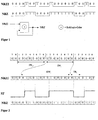
- the recoding can be done by EXCLUSIVE-OR operation Figure 1 can be performed.
- the information data words each have a length of 8 bits and are encoded into 14-bit information data words and then supplemented by the separating bits so that each channel data word has a length of Has 17 bits.
- the separation bits are also used to set the DC component or DC signal component to a minimum.
- the DC signal component is important because it is in the receiver, that is, in the playback device of a compact disc by circuitry Measures is determined and as a decision threshold is used to distinguish between zeros and ones.
- the creation of the DC component is explained in FIG. 2.
- the blocks of information words IW i are first recoded into the blocks of data words DW i and supplemented by suitable separating bits TR i .
- the NRZI-coded data stream thus obtained is brought into the form of the NRZ format on the recording medium, a "1" marking a transition at the beginning of the bit cell concerned and a "0" not marking a transition.
- the bit sequence labeled D W i and TR i has the signal sequence labeled SF on the record carrier, provided that idealized behavior is assumed for simplicity.
- the SF sequence has a non-zero DC component if the pulse lengths and the pause lengths are not identical.
- a frequently used measure for the direct component is the digital sum value DSV, which, assuming the above level assignment, is equal to the integral over the signal sequence SF.
- the DC component or DSV is of crucial importance when decoding the signal sequence SF, since it determines the decision threshold of the decoder.
- the decision threshold is to be minimized on the Average of the signal sequence recorded on the recording medium to adjust.
- DE-C 31 25 529 describes and claims Requirement to aim for the minimum DC component that Target demand, namely by means of a suitable decision threshold if possible to get little bit error, can not meet.
- the recorded one is recorded in a decoder geometric structure converted back into bit sequences.
- the digital data on a compact disc in the form of Wells (pits, optically inactive) of the same depth u and width b as well the rooms in between (Lands, optically active) saved.
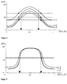
- the Information is represented by the varying length of the pits and lands, the lengths must meet the d, k condition. Because of the laser recording and injection molding duplication processes is for example the pit structure on the compact disc not ideally rectangular, but very rounded, as shown in Fig. 3 is.
- the short pits or lands occur significantly more frequently than the long pits or lands. Furthermore, due to the convolution effect between the pit structure and the reading beam geometry, the modulation amplitude of the reading signal SF is smaller for short pits or lands than for long pits or lands. Because of this, the short to medium pits have the greatest influence on the DC signal component SG, as can be seen from the example in Table 2.
- the single-signal constant components ⁇ SG i result from the read signal of a sequence of pits and lands of the same length i L T.
- the DC signal component ⁇ SG results from the superposition of all individual signal DC components ⁇ SG i , taking into account the probability of occurrence.
- the invention has for its object a method for recoding of digital information data words of the type mentioned at the beginning, where the bit and thus the data error rate compared to the known method is reduced.
- the present invention is based on knowledge from that the minimum DC component in practically no case the optimal decision threshold in the "receiver", ie in the decoder of the reader or player, but that the decision threshold have a value that deviates from the minimum DC signal component must if the lowest possible bit error rate is to be achieved. How results from the above consideration, the DC signal component to be set lies and therefore the decision threshold in the player is different than the minimum DC signal component.
- the invention proposes in the recoding of the information data words into the channel data words to be saved or transmitted make sure that the digital total value is set so that the most favorable value for the decision threshold in the player results.
- the invention takes advantage of the fact that in the player that in the decoder means only the data bits of the channel data word with respect to the Information is evaluated, but not the redundant separating bits. In the method according to the invention, therefore, changes for the recipient the data, in the case of the CD, for the user of the CD player, practically nothing, except that he enjoyed a more precise Playback of information is coming.
- a max is the maximum of the amplitudes A (i) of the read signal curves for different structure lengths i L T , to which the probability of occurrence densities p (i) are assigned.
- the size dx indicates the effective pit shortening.
- SG 1 (i) is the direct component of the read signal curve SF i1 , which is assigned to an optically active area (1) of length iL T.
- SG 0 (i) is the direct component of the read signal curve SF i0 , which is assigned to an optically inactive area (0) of length iL T.
- I defines the increment interval in bit cycles.
- the Growth rate (ZW) which is the signal DC component of the sequence of channel data words corresponds to a maximum digital sum value within a predetermined incremental interval is set, and that within each an increase interval determines the channel data for the channel words be that for the combinations of separating bits in question the digital sum values of the corresponding channel data words are formed and the difference with respect to the maximum total value is formed.
- the selection criterion for the selection of a channel data word candidate is preferably the smallest difference.
- the invention provides that from the set of candidates Candidates who are not a bit sequence in NRZI format are disregarded correspond between two bits "1" at least d and at most k Has bits "0".
- the constant component to be set from the frequency distribution of the lengths in succession Zeros or ones is calculated.
- the calculation can include other variables, namely the read waveform and the effective pit length variation.
- the typical shift of the individual direct components ⁇ SG i related to A max for the different structure lengths i can be found in Table 4 below:
- the actual decision threshold and thus the resulting DC signal component SGR must be optimally adjusted to the individual DC component SG i of the short pits.
- a DSV growth rate of -1 can be set. For this, the Bits of the split bit block used in each channel word.
- the data block which is composed of identical data words, for example, is unlimited and is initially available in the NRZI output format.
- the data block is supplemented by the separating bits TR and converted into the NRZ format.
- the received (scanned) Channel words decoded disregarding the separator bits, what concerns the information content, but only those mentioned at the beginning Fulfill purposes.
- the decision threshold is determined by determining the Signal DC component gained, which is an integration at the same time Division by time. To make the decision threshold in the decoder, that is, according to the invention compared to the minimum
- the growth interval must be small compared to the time constant of the Reading system in order not to influence the control loops of the reading system.
- the growth interval corresponds to a word length of Channel data word.
- the digital sum value DSV in the data stream is constantly decreasing, since the digital sum value is reduced by 1 in every incremental interval, in this example in each channel data word.
- the amount of the digital sum value would add up to an extremely high value for the entire data stream.
- the determination of the digital sum values is limited to finite, mutually adjacent growth intervals, for which purpose a number of channel data words, m max , is selected.
- the value m max thus corresponds to the number of channel data words that is available at most for changing the digital sum value DSV until DSV max is reached.
- the product of the growth rate ZW and the growth interval T ZW in the present example gives the value -1, so that the amount of the maximum digital sum value DSV max corresponds to the number of channel data words which are required for the change until DSV max is reached is available.
- m max would have to be increased with the same value of DSV max .
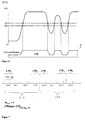
- FIG. 7 shows the beginning of the data stream which was obtained from information data words by inserting separating bit blocks.
- the value m max is set to 4 here.
- a channel data word CW consists of a data word with 14 bits and a separating bit block TR which contains three bits.
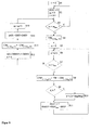
- the index counter i is introduced for the method for setting the changed DC signal component explained below with reference to FIG. 8. It is increased by 1 after each section comprising 4 channel data words.
- the index m is increased cyclically from 0 to 3, since the maximum value for the section of channel data words up to DSV max was set to 4 here.
- step S2 the digital sum value DSV is set to 0, and the cyclically running value of m within the maximum number m max of channel data words available for changing DSV is also set to 0.
- the index counter i is increased by 1, i.e. set to 1 in the first pass.
- step S4 the data word corresponding to the specified index is fetched, in the present example, data word DW 0 , the first data word in the data stream considered here.
- an index counter n is set to 0.
- steps S9 and S10 it is checked whether the channel data word which was formed in step S8, the d, k condition is satisfied. This condition was explained above. Steps S9 and S10 separate such channel data words that do not meet the d, k condition.
- step S11 the digital sum value belonging to the current index n is queried. This digital sum value depends on the data word and the separating bit block added to it in accordance with step S8.
- the difference value DDSV n between DSV max and the previously determined digital total value DSV n is determined in font S11. With three separating bits, this loop is therefore run through eight times with steps S6-S11, so that a difference value DDSV n results from step S11 eight times.
- step S7 proceeds to step S12.
- the channel word CW j is selected in step S13 from the 8 channel words formed in step S8, which corresponds to the smallest difference value. This channel word is then generated on the compact disc in the case of the present example.
- step S14 the increase or accumulation of the running digital sum value DSV around the digital sum value, the corresponds to the previously found smallest difference in step S11.
- the value DSV j added in step S14 corresponds to the maximum digital (n ⁇ x) digital sum value that was specified in the last eight passes of the loop in steps S6-S11.
- step S13 a channel data word is selected which corresponds to a very large digital sum value which is determined in step S11 has been. If the value DSV n in step S11 is almost as large as step DSV max , there is a correspondingly small difference DDSV n . The value DSV then obtained in step S14 by summation is then close to the value DSV max , so that the subsequently selected channel words have only a slight increase in the digital sum value.
- the method presented here is for setting a decision threshold when transferring or caching of digital information data words in principle for all Storage and transmission procedures applicable if applicable to these It can be demonstrated that the optimal decision threshold differs from the decision threshold that corresponds to the minimum DC signal component corresponds.
- a major advantage of the method described is that the readout system its structure does not have to be changed since the separating bits be eliminated in the data evaluation and thus, except for the desired one Shift of the DC signal component, no effect on the have further data processing in the device.
- the procedure is not limited to the compact disc case described, but can be on equivalent disks that have the setting allow a growth rate in the DSV to be applied.
- recording systems such as D igital V ersatile D isc (DVD) are known in which each of n 1-bit long information data word fulfill a certain number of different n 2 -bit long channel data words which are equivalent in their significance and the required channel conditions , can be assigned.
- DVD D igital V ersatile D isc
- the encoder can make a selection from the possible channel data words in such a way that a required growth rate can be set.
- the procedure for setting the growth rate in such a system is equivalent to the structure shown in FIG.
- a single information data word is then again assigned to each channel data word from the specific number of different, equivalent, n 2 -bit long channel data words.
Landscapes
- Engineering & Computer Science (AREA)
- Signal Processing (AREA)
- Physics & Mathematics (AREA)
- Spectroscopy & Molecular Physics (AREA)
- Computer Networks & Wireless Communication (AREA)
- Signal Processing For Digital Recording And Reproducing (AREA)
Priority Applications (4)
| Application Number | Priority Date | Filing Date | Title |
|---|---|---|---|
| EP19980117843 EP0991069B1 (fr) | 1998-09-15 | 1998-09-21 | Méthode et appareil pour coder des données d'information numériques et support d'enregistrement avec une structure d'information obtenue par cette méthode |
| PCT/EP1999/006808 WO2000016327A1 (fr) | 1998-09-15 | 1999-09-14 | Procede et dispositif pour decoder des mots de donnees de renseignements numeriques et support d'enregistrement muni de cette structure d'information obtenue a l'aide dudit procede |
| DE19981844T DE19981844D2 (de) | 1998-09-15 | 1999-09-14 | Verfahren und Vorrichtung zum Umkodieren Digitaler Informations-Datenwörter und Aufzeichnungsträger mit gemäss diesem Verfahren erzeugter Informationsstruktur |
| AU58634/99A AU5863499A (en) | 1998-09-15 | 1999-09-14 | Method and device for recoding digital information data words and a recording medium comprising an information structure according to said method |
Applications Claiming Priority (3)
| Application Number | Priority Date | Filing Date | Title |
|---|---|---|---|
| EP98117505 | 1998-09-15 | ||
| EP98117505 | 1998-09-15 | ||
| EP19980117843 EP0991069B1 (fr) | 1998-09-15 | 1998-09-21 | Méthode et appareil pour coder des données d'information numériques et support d'enregistrement avec une structure d'information obtenue par cette méthode |
Publications (2)
| Publication Number | Publication Date |
|---|---|
| EP0991069A1 true EP0991069A1 (fr) | 2000-04-05 |
| EP0991069B1 EP0991069B1 (fr) | 2001-03-28 |
Family
ID=26149637
Family Applications (1)
| Application Number | Title | Priority Date | Filing Date |
|---|---|---|---|
| EP19980117843 Expired - Lifetime EP0991069B1 (fr) | 1998-09-15 | 1998-09-21 | Méthode et appareil pour coder des données d'information numériques et support d'enregistrement avec une structure d'information obtenue par cette méthode |
Country Status (4)
| Country | Link |
|---|---|
| EP (1) | EP0991069B1 (fr) |
| AU (1) | AU5863499A (fr) |
| DE (1) | DE19981844D2 (fr) |
| WO (1) | WO2000016327A1 (fr) |
Citations (8)
| Publication number | Priority date | Publication date | Assignee | Title |
|---|---|---|---|---|
| DE3125529A1 (de) * | 1980-07-14 | 1982-05-13 | Naamloze Vennootschap Philips' Gloeilampenfabrieken, 5621 Eindhoven | "verfahren zum umkodieren einer folge von datenbits in eine folge von kanalbits, anordnung zum dekodieren der nach diesem verfahren kodierten kanalbits und aufzeichnungstraeger mit einer informationsstruktur" |
| US4539691A (en) * | 1981-09-11 | 1985-09-03 | Sony Corporation | Method and apparatus for encoding a binary digital information signal |
| EP0396346A1 (fr) * | 1989-04-28 | 1990-11-07 | Canon Kabushiki Kaisha | Dispositif de codage pour code de détection d'erreurs et de correction d'erreurs |
| US5469162A (en) * | 1992-03-31 | 1995-11-21 | Sony Corporation | Data modulation method |
| EP0691750A1 (fr) * | 1994-07-08 | 1996-01-10 | Victor Company Of Japan, Limited | Procédé pour la modulation ou démodulation numérique et appareil pour utiliser cette modulation ou démodulation |
| US5508701A (en) * | 1993-07-06 | 1996-04-16 | Mitsubishi Denki Kabushiki Kaisha | Data conversion method and recording and reproduction apparatus |
| US5627694A (en) * | 1992-02-19 | 1997-05-06 | Mitsubishi Denki Kabushiki Kaisha | Recording/reproducing apparatus for recording and reproducing multiple kinds of digital signals having different data amounts per unit time |
| US5742243A (en) * | 1995-02-20 | 1998-04-21 | Pioneer Electric Corporation | Method and apparatus for reducing DC component of RLL codes |
-
1998
- 1998-09-21 EP EP19980117843 patent/EP0991069B1/fr not_active Expired - Lifetime
-
1999
- 1999-09-14 AU AU58634/99A patent/AU5863499A/en not_active Abandoned
- 1999-09-14 DE DE19981844T patent/DE19981844D2/de not_active Expired - Fee Related
- 1999-09-14 WO PCT/EP1999/006808 patent/WO2000016327A1/fr not_active Ceased
Patent Citations (8)
| Publication number | Priority date | Publication date | Assignee | Title |
|---|---|---|---|---|
| DE3125529A1 (de) * | 1980-07-14 | 1982-05-13 | Naamloze Vennootschap Philips' Gloeilampenfabrieken, 5621 Eindhoven | "verfahren zum umkodieren einer folge von datenbits in eine folge von kanalbits, anordnung zum dekodieren der nach diesem verfahren kodierten kanalbits und aufzeichnungstraeger mit einer informationsstruktur" |
| US4539691A (en) * | 1981-09-11 | 1985-09-03 | Sony Corporation | Method and apparatus for encoding a binary digital information signal |
| EP0396346A1 (fr) * | 1989-04-28 | 1990-11-07 | Canon Kabushiki Kaisha | Dispositif de codage pour code de détection d'erreurs et de correction d'erreurs |
| US5627694A (en) * | 1992-02-19 | 1997-05-06 | Mitsubishi Denki Kabushiki Kaisha | Recording/reproducing apparatus for recording and reproducing multiple kinds of digital signals having different data amounts per unit time |
| US5469162A (en) * | 1992-03-31 | 1995-11-21 | Sony Corporation | Data modulation method |
| US5508701A (en) * | 1993-07-06 | 1996-04-16 | Mitsubishi Denki Kabushiki Kaisha | Data conversion method and recording and reproduction apparatus |
| EP0691750A1 (fr) * | 1994-07-08 | 1996-01-10 | Victor Company Of Japan, Limited | Procédé pour la modulation ou démodulation numérique et appareil pour utiliser cette modulation ou démodulation |
| US5742243A (en) * | 1995-02-20 | 1998-04-21 | Pioneer Electric Corporation | Method and apparatus for reducing DC component of RLL codes |
Non-Patent Citations (3)
| Title |
|---|
| ANONYMOUS: "Charge Constrained Byte Oriented (0,3) Code. December 1976.", IBM TECHNICAL DISCLOSURE BULLETIN, vol. 19, no. 7, December 1976 (1976-12-01), New York, US, pages 2715 - 2717, XP002088647 * |
| SEEHAUSEN G.: "influence of pit geometry on read-out signals of optical data disc drives", IEEE INTERNATIONAL PUBLICATION, (LONDON) ELECTRONICS LETTERS, vol. 28, no. 18, August 1992 (1992-08-01), pages 1709 - 1711, XP002088646 * |
| TANG D T ET AL: "Block codes for a class of constrained noiseless channels", INFORMATION AND CONTROL, DEC. 1970, USA, vol. 17, no. 5, ISSN 0019-9958, pages 436 - 461, XP002088712 * |
Also Published As
| Publication number | Publication date |
|---|---|
| DE19981844D2 (de) | 2001-06-21 |
| WO2000016327A1 (fr) | 2000-03-23 |
| AU5863499A (en) | 2000-04-03 |
| EP0991069B1 (fr) | 2001-03-28 |
Similar Documents
| Publication | Publication Date | Title |
|---|---|---|
| DE69117035T2 (de) | Digitale Modulation | |
| DE3125529C2 (de) | Verfahren zum Umkodieren einer Folge von Datenbits in eine Folge von Kanalbits, Anordnung zum Dekodieren der nach diesem Verfahren kodierten Kanalbits und Aufzeichnungsträger mit einer gemäß diesem Verfahren erzeugten Informationsstruktur | |
| DE69614458T2 (de) | Optisches Datenspeichermedium | |
| DE69714790T2 (de) | Optische Platte, optische Plattenvorrichtung und Verfahren zur Wiedergabe von Informationen auf der optischen Platte | |
| DE60133329T2 (de) | Aufzeichnung zusätzlicher Daten mit verbindenden Rahmen und verschiedenen Synchronisationssignalen | |
| DE69118244T2 (de) | Spuradressenmuster für ein Magnetplattengerät | |
| DE69421464T2 (de) | Optischer Aufzeichnungsträger, Methode zur Aufzeichnung von auf den Aufzeichnungsträgern aufgenommenen Informationssignalen und Vorrichtung zur Datenaufzeichnung für das Herstellen des optischen Aufzeichnungsträgers | |
| DE69131142T2 (de) | Datenaufzeichnungs- und Wiedergabegerät | |
| DE3852186T2 (de) | Verfahren zum Formatieren einer Platte, Verfahren zum Lesen und Schreiben auf eine so formatierte Platte, Plattenantrieb mit so formatierter Platte und so formatierte Platte. | |
| DE69327740T2 (de) | Verfahren und Gerät zur Modulation und Demodulation | |
| DE3587982T2 (de) | Verfahren und Gerät zur Positionierung von Abtastköpfen mittels digitaler Umsetzung analoger Signale. | |
| DE69612955T4 (de) | Verfahren zur umwandlung von m-bit-informationsworten in ein moduliertes signal, verfahren zur herstellung eines aufzeichnungsträgers, codiervorrichtung, vorrichtung, aufzeichnungsvorrichtung, signal sowie aufzeichnungsträger | |
| DE69522650T2 (de) | Signalmodulations- und -demodulationsverfahren und -vorrichtung | |
| DE69321746T2 (de) | Datenmodulations und -demodulationsverfahren und -vorrichtung | |
| DE69614338T2 (de) | Optisches Informationsaufzeichnungsmedium | |
| CH662202A5 (de) | Verfahren zum aufzeichnen eines binaeren informationssignals auf einem aufzeichnungstraeger mit einer strahlungsempfindlichen informationsschicht. | |
| DE69700462T2 (de) | Vorrichtung und Verfahren zur Aufzeichnung von Informationen | |
| DE2828219C2 (fr) | ||
| DE3122755A1 (de) | "verfahren zum kodieren von datenbits auf einem aufzeichnungstraeger, anordnung zum durchfuehren des verfahrens und aufzeichnungstraeger mit einer informationsstruktur" | |
| DE3434418C2 (fr) | ||
| DE69426482T2 (de) | Verfahren zur Herstellung eines optischen Informationsträgers, Vorrichtung zur Durchführung des Verfahrens, und nach diesem Verfahren hergestellter optischer Informationsträger | |
| DE2637963A1 (de) | Verfahren und vorrichtung zur aufnahme digitaler daten auf ein magnetband | |
| DE2430685A1 (de) | Verfahren und vorrichtung zur schnellen digitalen modulation | |
| DE69212027T2 (de) | Verfahren und Vorrichtung zur digitalen Modulation | |
| DE69626244T2 (de) | Binärkodierung von Signalen und digitale Signalverarbeitung |
Legal Events
| Date | Code | Title | Description |
|---|---|---|---|
| PUAI | Public reference made under article 153(3) epc to a published international application that has entered the european phase |
Free format text: ORIGINAL CODE: 0009012 |
|
| 17P | Request for examination filed |
Effective date: 19980921 |
|
| AK | Designated contracting states |
Kind code of ref document: A1 Designated state(s): AT BE CH CY DE DK ES FI FR GB GR IE IT LI LU MC NL PT SE |
|
| AX | Request for extension of the european patent |
Free format text: AL;LT;LV;MK;RO;SI |
|
| GRAG | Despatch of communication of intention to grant |
Free format text: ORIGINAL CODE: EPIDOS AGRA |
|
| GRAG | Despatch of communication of intention to grant |
Free format text: ORIGINAL CODE: EPIDOS AGRA |
|
| GRAH | Despatch of communication of intention to grant a patent |
Free format text: ORIGINAL CODE: EPIDOS IGRA |
|
| AKX | Designation fees paid |
Free format text: AT BE CH CY DE DK ES FI FR GB GR IE IT LI LU MC NL PT SE |
|
| AXX | Extension fees paid |
Free format text: AL PAYMENT 20000926;LT PAYMENT 20000926;LV PAYMENT 20000926;MK PAYMENT 20000926;RO PAYMENT 20000926;SI PAYMENT 20000926 |
|
| GRAH | Despatch of communication of intention to grant a patent |
Free format text: ORIGINAL CODE: EPIDOS IGRA |
|
| GRAA | (expected) grant |
Free format text: ORIGINAL CODE: 0009210 |
|
| AK | Designated contracting states |
Kind code of ref document: B1 Designated state(s): AT BE CH CY DE DK ES FI FR GB GR IE IT LI LU MC NL PT SE |
|
| AX | Request for extension of the european patent |
Free format text: AL PAYMENT 20000926;LT PAYMENT 20000926;LV PAYMENT 20000926;MK PAYMENT 20000926;RO PAYMENT 20000926;SI PAYMENT 20000926 |
|
| PG25 | Lapsed in a contracting state [announced via postgrant information from national office to epo] |
Ref country code: NL Free format text: LAPSE BECAUSE OF FAILURE TO SUBMIT A TRANSLATION OF THE DESCRIPTION OR TO PAY THE FEE WITHIN THE PRESCRIBED TIME-LIMIT Effective date: 20010328 Ref country code: IT Free format text: LAPSE BECAUSE OF FAILURE TO SUBMIT A TRANSLATION OF THE DESCRIPTION OR TO PAY THE FEE WITHIN THE PRE;WARNING: LAPSES OF ITALIAN PATENTS WITH EFFECTIVE DATE BEFORE 2007 MAY HAVE OCCURRED AT ANY TIME BEFORE 2007. THE CORRECT EFFECTIVE DATE MAY BE DIFFERENT FROM THE ONE RECORDED.SCRIBED TIME-LIMIT Effective date: 20010328 Ref country code: IE Free format text: LAPSE BECAUSE OF FAILURE TO SUBMIT A TRANSLATION OF THE DESCRIPTION OR TO PAY THE FEE WITHIN THE PRESCRIBED TIME-LIMIT Effective date: 20010328 Ref country code: GB Free format text: LAPSE BECAUSE OF FAILURE TO SUBMIT A TRANSLATION OF THE DESCRIPTION OR TO PAY THE FEE WITHIN THE PRESCRIBED TIME-LIMIT Effective date: 20010328 Ref country code: FR Free format text: LAPSE BECAUSE OF FAILURE TO SUBMIT A TRANSLATION OF THE DESCRIPTION OR TO PAY THE FEE WITHIN THE PRESCRIBED TIME-LIMIT Effective date: 20010328 Ref country code: FI Free format text: LAPSE BECAUSE OF FAILURE TO SUBMIT A TRANSLATION OF THE DESCRIPTION OR TO PAY THE FEE WITHIN THE PRESCRIBED TIME-LIMIT Effective date: 20010328 Ref country code: CY Free format text: LAPSE BECAUSE OF NON-PAYMENT OF DUE FEES Effective date: 20010328 |
|
| REF | Corresponds to: |
Ref document number: 200160 Country of ref document: AT Date of ref document: 20010415 Kind code of ref document: T |
|
| REG | Reference to a national code |
Ref country code: CH Ref legal event code: EP |
|
| REG | Reference to a national code |
Ref country code: IE Ref legal event code: FG4D Free format text: GERMAN |
|
| REF | Corresponds to: |
Ref document number: 59800578 Country of ref document: DE Date of ref document: 20010503 |
|
| PG25 | Lapsed in a contracting state [announced via postgrant information from national office to epo] |
Ref country code: SE Free format text: LAPSE BECAUSE OF FAILURE TO SUBMIT A TRANSLATION OF THE DESCRIPTION OR TO PAY THE FEE WITHIN THE PRESCRIBED TIME-LIMIT Effective date: 20010628 Ref country code: PT Free format text: LAPSE BECAUSE OF FAILURE TO SUBMIT A TRANSLATION OF THE DESCRIPTION OR TO PAY THE FEE WITHIN THE PRESCRIBED TIME-LIMIT Effective date: 20010628 Ref country code: DK Free format text: LAPSE BECAUSE OF FAILURE TO SUBMIT A TRANSLATION OF THE DESCRIPTION OR TO PAY THE FEE WITHIN THE PRESCRIBED TIME-LIMIT Effective date: 20010628 |
|
| PG25 | Lapsed in a contracting state [announced via postgrant information from national office to epo] |
Ref country code: GR Free format text: LAPSE BECAUSE OF FAILURE TO SUBMIT A TRANSLATION OF THE DESCRIPTION OR TO PAY THE FEE WITHIN THE PRESCRIBED TIME-LIMIT Effective date: 20010629 |
|
| EN | Fr: translation not filed | ||
| NLV1 | Nl: lapsed or annulled due to failure to fulfill the requirements of art. 29p and 29m of the patents act | ||
| PG25 | Lapsed in a contracting state [announced via postgrant information from national office to epo] |
Ref country code: MC Free format text: LAPSE BECAUSE OF NON-PAYMENT OF DUE FEES Effective date: 20010921 Ref country code: LU Free format text: LAPSE BECAUSE OF NON-PAYMENT OF DUE FEES Effective date: 20010921 Ref country code: AT Free format text: LAPSE BECAUSE OF NON-PAYMENT OF DUE FEES Effective date: 20010921 |
|
| GBV | Gb: ep patent (uk) treated as always having been void in accordance with gb section 77(7)/1977 [no translation filed] |
Effective date: 20010328 |
|
| PG25 | Lapsed in a contracting state [announced via postgrant information from national office to epo] |
Ref country code: ES Free format text: LAPSE BECAUSE OF FAILURE TO SUBMIT A TRANSLATION OF THE DESCRIPTION OR TO PAY THE FEE WITHIN THE PRESCRIBED TIME-LIMIT Effective date: 20010927 |
|
| PG25 | Lapsed in a contracting state [announced via postgrant information from national office to epo] |
Ref country code: BE Free format text: LAPSE BECAUSE OF NON-PAYMENT OF DUE FEES Effective date: 20010930 |
|
| REG | Reference to a national code |
Ref country code: IE Ref legal event code: FD4D |
|
| PLBE | No opposition filed within time limit |
Free format text: ORIGINAL CODE: 0009261 |
|
| STAA | Information on the status of an ep patent application or granted ep patent |
Free format text: STATUS: NO OPPOSITION FILED WITHIN TIME LIMIT |
|
| 26N | No opposition filed | ||
| BERE | Be: lapsed |
Owner name: SEEHAUSEN GERHARD Effective date: 20010930 |
|
| PG25 | Lapsed in a contracting state [announced via postgrant information from national office to epo] |
Ref country code: LI Free format text: LAPSE BECAUSE OF NON-PAYMENT OF DUE FEES Effective date: 20020930 Ref country code: CH Free format text: LAPSE BECAUSE OF NON-PAYMENT OF DUE FEES Effective date: 20020930 |
|
| REG | Reference to a national code |
Ref country code: CH Ref legal event code: PL |
|
| PGFP | Annual fee paid to national office [announced via postgrant information from national office to epo] |
Ref country code: DE Payment date: 20051125 Year of fee payment: 8 |
|
| PG25 | Lapsed in a contracting state [announced via postgrant information from national office to epo] |
Ref country code: DE Free format text: LAPSE BECAUSE OF NON-PAYMENT OF DUE FEES Effective date: 20070403 |