EP0991069A1 - Method and apparatus for coding digital information data and recording medium with structure of information obtained with that method - Google Patents
Method and apparatus for coding digital information data and recording medium with structure of information obtained with that method Download PDFInfo
- Publication number
- EP0991069A1 EP0991069A1 EP98117843A EP98117843A EP0991069A1 EP 0991069 A1 EP0991069 A1 EP 0991069A1 EP 98117843 A EP98117843 A EP 98117843A EP 98117843 A EP98117843 A EP 98117843A EP 0991069 A1 EP0991069 A1 EP 0991069A1
- Authority
- EP
- European Patent Office
- Prior art keywords
- data words
- channel data
- signal
- signal component
- value
- Prior art date
- Legal status (The legal status is an assumption and is not a legal conclusion. Google has not performed a legal analysis and makes no representation as to the accuracy of the status listed.)
- Granted
Links
- 238000000034 method Methods 0.000 title claims abstract description 38
- 230000007704 transition Effects 0.000 claims description 5
- 238000009826 distribution Methods 0.000 claims description 3
- 238000013507 mapping Methods 0.000 claims description 2
- 230000005540 biological transmission Effects 0.000 abstract description 6
- 238000004519 manufacturing process Methods 0.000 abstract description 5
- 238000003860 storage Methods 0.000 abstract description 3
- 239000013589 supplement Substances 0.000 abstract description 2
- 230000002596 correlated effect Effects 0.000 abstract 1
- 230000000694 effects Effects 0.000 description 5
- 108010076504 Protein Sorting Signals Proteins 0.000 description 4
- 230000008859 change Effects 0.000 description 4
- 230000003247 decreasing effect Effects 0.000 description 4
- 238000004364 calculation method Methods 0.000 description 3
- 230000010354 integration Effects 0.000 description 3
- 230000008569 process Effects 0.000 description 3
- 238000004904 shortening Methods 0.000 description 3
- 230000008901 benefit Effects 0.000 description 2
- 230000001419 dependent effect Effects 0.000 description 2
- 238000005516 engineering process Methods 0.000 description 2
- 230000002349 favourable effect Effects 0.000 description 2
- 238000001746 injection moulding Methods 0.000 description 2
- 230000003287 optical effect Effects 0.000 description 2
- BDAGIHXWWSANSR-UHFFFAOYSA-M Formate Chemical compound [O-]C=O BDAGIHXWWSANSR-UHFFFAOYSA-M 0.000 description 1
- 238000009825 accumulation Methods 0.000 description 1
- 238000006243 chemical reaction Methods 0.000 description 1
- 238000012937 correction Methods 0.000 description 1
- 238000011157 data evaluation Methods 0.000 description 1
- 238000011161 development Methods 0.000 description 1
- 238000011835 investigation Methods 0.000 description 1
- 230000001788 irregular Effects 0.000 description 1
- 238000005259 measurement Methods 0.000 description 1
- 230000000737 periodic effect Effects 0.000 description 1
- 239000011295 pitch Substances 0.000 description 1
- 238000012545 processing Methods 0.000 description 1
- 239000000047 product Substances 0.000 description 1
- 230000009467 reduction Effects 0.000 description 1
- 238000000926 separation method Methods 0.000 description 1
- 239000000758 substrate Substances 0.000 description 1
- 230000003746 surface roughness Effects 0.000 description 1
- 230000005641 tunneling Effects 0.000 description 1
Images

Classifications
-
- G—PHYSICS
- G11—INFORMATION STORAGE
- G11B—INFORMATION STORAGE BASED ON RELATIVE MOVEMENT BETWEEN RECORD CARRIER AND TRANSDUCER
- G11B20/00—Signal processing not specific to the method of recording or reproducing; Circuits therefor
- G11B20/10—Digital recording or reproducing
- G11B20/10009—Improvement or modification of read or write signals
- G11B20/10046—Improvement or modification of read or write signals filtering or equalising, e.g. setting the tap weights of an FIR filter
- G11B20/10203—Improvement or modification of read or write signals filtering or equalising, e.g. setting the tap weights of an FIR filter baseline correction
-
- G—PHYSICS
- G11—INFORMATION STORAGE
- G11B—INFORMATION STORAGE BASED ON RELATIVE MOVEMENT BETWEEN RECORD CARRIER AND TRANSDUCER
- G11B20/00—Signal processing not specific to the method of recording or reproducing; Circuits therefor
- G11B20/10—Digital recording or reproducing
- G11B20/14—Digital recording or reproducing using self-clocking codes
- G11B20/1403—Digital recording or reproducing using self-clocking codes characterised by the use of two levels
- G11B20/1423—Code representation depending on subsequent bits, e.g. delay modulation, double density code, Miller code
- G11B20/1426—Code representation depending on subsequent bits, e.g. delay modulation, double density code, Miller code conversion to or from block codes or representations thereof
-
- H—ELECTRICITY
- H04—ELECTRIC COMMUNICATION TECHNIQUE
- H04L—TRANSMISSION OF DIGITAL INFORMATION, e.g. TELEGRAPHIC COMMUNICATION
- H04L25/00—Baseband systems
- H04L25/38—Synchronous or start-stop systems, e.g. for Baudot code
- H04L25/40—Transmitting circuits; Receiving circuits
- H04L25/49—Transmitting circuits; Receiving circuits using code conversion at the transmitter; using predistortion; using insertion of idle bits for obtaining a desired frequency spectrum; using three or more amplitude levels ; Baseband coding techniques specific to data transmission systems
- H04L25/4906—Transmitting circuits; Receiving circuits using code conversion at the transmitter; using predistortion; using insertion of idle bits for obtaining a desired frequency spectrum; using three or more amplitude levels ; Baseband coding techniques specific to data transmission systems using binary codes
Definitions
- the invention relates to a method for recoding digital information data words in channel data words, e.g. by adding a Blocks from a set of separating bit blocks to one preceding one each adjacent information data word or by mapping one each Information data word on one of a subset of channel data words, to set a specific DC component, for what a set of candidates for channel data words is formed from the a channel data word is selected according to a selection criterion; in addition, the invention relates to a recording medium according to information structure generated by this method.
- Channel data words implies that these data words are stored and / or transmitted data words, i.e. data words, that get from a data word source to a data word sink.
- the data to be stored on a compact disc are initially stored as information data words each with a length of 14 bits.
- This Information data words are converted into channel data words by a further three bits (so-called separating bits) are added to the four bits.
- the separator bits are chosen so that only predetermined sequences of only zeros or ones occur.
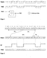
- the information to be processed is in the form of data words or samples, which are composed of the binary logical digit coefficients (bit) "0" or "1", whereby for Example the bit "1" according to the NRZ code identifies an optically (or magnetically) active area and the bit "0" an optically (or magnetically) inactive area.
- bit binary logical digit coefficients
- NRZI NRZI coding
- the recoding can be done by EXCLUSIVE-OR operation Figure 1 can be performed.
- the information data words each have a length of 8 bits and are encoded into 14-bit information data words and then supplemented by the separating bits so that each channel data word has a length of Has 17 bits.
- the separation bits are also used to set the DC component or DC signal component to a minimum.
- the DC signal component is important because it is in the receiver, that is, in the playback device of a compact disc by circuitry Measures is determined and as a decision threshold is used to distinguish between zeros and ones.
- the creation of the DC component is explained in FIG. 2.
- the blocks of information words IW i are first recoded into the blocks of data words DW i and supplemented by suitable separating bits TR i .
- the NRZI-coded data stream thus obtained is brought into the form of the NRZ format on the recording medium, a "1" marking a transition at the beginning of the bit cell concerned and a "0" not marking a transition.
- the bit sequence labeled D W i and TR i has the signal sequence labeled SF on the record carrier, provided that idealized behavior is assumed for simplicity.
- the SF sequence has a non-zero DC component if the pulse lengths and the pause lengths are not identical.
- a frequently used measure for the direct component is the digital sum value DSV, which, assuming the above level assignment, is equal to the integral over the signal sequence SF.
- the DC component or DSV is of crucial importance when decoding the signal sequence SF, since it determines the decision threshold of the decoder.
- the decision threshold is to be minimized on the Average of the signal sequence recorded on the recording medium to adjust.
- DE-C 31 25 529 describes and claims Requirement to aim for the minimum DC component that Target demand, namely by means of a suitable decision threshold if possible to get little bit error, can not meet.
- the recorded one is recorded in a decoder geometric structure converted back into bit sequences.
- the digital data on a compact disc in the form of Wells (pits, optically inactive) of the same depth u and width b as well the rooms in between (Lands, optically active) saved.
- the Information is represented by the varying length of the pits and lands, the lengths must meet the d, k condition. Because of the laser recording and injection molding duplication processes is for example the pit structure on the compact disc not ideally rectangular, but very rounded, as shown in Fig. 3 is.
- the short pits or lands occur significantly more frequently than the long pits or lands. Furthermore, due to the convolution effect between the pit structure and the reading beam geometry, the modulation amplitude of the reading signal SF is smaller for short pits or lands than for long pits or lands. Because of this, the short to medium pits have the greatest influence on the DC signal component SG, as can be seen from the example in Table 2.
- the single-signal constant components ⁇ SG i result from the read signal of a sequence of pits and lands of the same length i L T.
- the DC signal component ⁇ SG results from the superposition of all individual signal DC components ⁇ SG i , taking into account the probability of occurrence.
- the invention has for its object a method for recoding of digital information data words of the type mentioned at the beginning, where the bit and thus the data error rate compared to the known method is reduced.
- the present invention is based on knowledge from that the minimum DC component in practically no case the optimal decision threshold in the "receiver", ie in the decoder of the reader or player, but that the decision threshold have a value that deviates from the minimum DC signal component must if the lowest possible bit error rate is to be achieved. How results from the above consideration, the DC signal component to be set lies and therefore the decision threshold in the player is different than the minimum DC signal component.
- the invention proposes in the recoding of the information data words into the channel data words to be saved or transmitted make sure that the digital total value is set so that the most favorable value for the decision threshold in the player results.
- the invention takes advantage of the fact that in the player that in the decoder means only the data bits of the channel data word with respect to the Information is evaluated, but not the redundant separating bits. In the method according to the invention, therefore, changes for the recipient the data, in the case of the CD, for the user of the CD player, practically nothing, except that he enjoyed a more precise Playback of information is coming.
- a max is the maximum of the amplitudes A (i) of the read signal curves for different structure lengths i L T , to which the probability of occurrence densities p (i) are assigned.
- the size dx indicates the effective pit shortening.
- SG 1 (i) is the direct component of the read signal curve SF i1 , which is assigned to an optically active area (1) of length iL T.
- SG 0 (i) is the direct component of the read signal curve SF i0 , which is assigned to an optically inactive area (0) of length iL T.
- I defines the increment interval in bit cycles.
- the Growth rate (ZW) which is the signal DC component of the sequence of channel data words corresponds to a maximum digital sum value within a predetermined incremental interval is set, and that within each an increase interval determines the channel data for the channel words be that for the combinations of separating bits in question the digital sum values of the corresponding channel data words are formed and the difference with respect to the maximum total value is formed.
- the selection criterion for the selection of a channel data word candidate is preferably the smallest difference.
- the invention provides that from the set of candidates Candidates who are not a bit sequence in NRZI format are disregarded correspond between two bits "1" at least d and at most k Has bits "0".
- the constant component to be set from the frequency distribution of the lengths in succession Zeros or ones is calculated.
- the calculation can include other variables, namely the read waveform and the effective pit length variation.
- the typical shift of the individual direct components ⁇ SG i related to A max for the different structure lengths i can be found in Table 4 below:
- the actual decision threshold and thus the resulting DC signal component SGR must be optimally adjusted to the individual DC component SG i of the short pits.
- a DSV growth rate of -1 can be set. For this, the Bits of the split bit block used in each channel word.
- the data block which is composed of identical data words, for example, is unlimited and is initially available in the NRZI output format.
- the data block is supplemented by the separating bits TR and converted into the NRZ format.
- the received (scanned) Channel words decoded disregarding the separator bits, what concerns the information content, but only those mentioned at the beginning Fulfill purposes.
- the decision threshold is determined by determining the Signal DC component gained, which is an integration at the same time Division by time. To make the decision threshold in the decoder, that is, according to the invention compared to the minimum
- the growth interval must be small compared to the time constant of the Reading system in order not to influence the control loops of the reading system.
- the growth interval corresponds to a word length of Channel data word.
- the digital sum value DSV in the data stream is constantly decreasing, since the digital sum value is reduced by 1 in every incremental interval, in this example in each channel data word.
- the amount of the digital sum value would add up to an extremely high value for the entire data stream.
- the determination of the digital sum values is limited to finite, mutually adjacent growth intervals, for which purpose a number of channel data words, m max , is selected.
- the value m max thus corresponds to the number of channel data words that is available at most for changing the digital sum value DSV until DSV max is reached.
- the product of the growth rate ZW and the growth interval T ZW in the present example gives the value -1, so that the amount of the maximum digital sum value DSV max corresponds to the number of channel data words which are required for the change until DSV max is reached is available.
- m max would have to be increased with the same value of DSV max .
- FIG. 7 shows the beginning of the data stream which was obtained from information data words by inserting separating bit blocks.
- the value m max is set to 4 here.
- a channel data word CW consists of a data word with 14 bits and a separating bit block TR which contains three bits.
- the index counter i is introduced for the method for setting the changed DC signal component explained below with reference to FIG. 8. It is increased by 1 after each section comprising 4 channel data words.
- the index m is increased cyclically from 0 to 3, since the maximum value for the section of channel data words up to DSV max was set to 4 here.
- step S2 the digital sum value DSV is set to 0, and the cyclically running value of m within the maximum number m max of channel data words available for changing DSV is also set to 0.
- the index counter i is increased by 1, i.e. set to 1 in the first pass.
- step S4 the data word corresponding to the specified index is fetched, in the present example, data word DW 0 , the first data word in the data stream considered here.
- an index counter n is set to 0.
- steps S9 and S10 it is checked whether the channel data word which was formed in step S8, the d, k condition is satisfied. This condition was explained above. Steps S9 and S10 separate such channel data words that do not meet the d, k condition.
- step S11 the digital sum value belonging to the current index n is queried. This digital sum value depends on the data word and the separating bit block added to it in accordance with step S8.
- the difference value DDSV n between DSV max and the previously determined digital total value DSV n is determined in font S11. With three separating bits, this loop is therefore run through eight times with steps S6-S11, so that a difference value DDSV n results from step S11 eight times.
- step S7 proceeds to step S12.
- the channel word CW j is selected in step S13 from the 8 channel words formed in step S8, which corresponds to the smallest difference value. This channel word is then generated on the compact disc in the case of the present example.
- step S14 the increase or accumulation of the running digital sum value DSV around the digital sum value, the corresponds to the previously found smallest difference in step S11.
- the value DSV j added in step S14 corresponds to the maximum digital (n ⁇ x) digital sum value that was specified in the last eight passes of the loop in steps S6-S11.
- step S13 a channel data word is selected which corresponds to a very large digital sum value which is determined in step S11 has been. If the value DSV n in step S11 is almost as large as step DSV max , there is a correspondingly small difference DDSV n . The value DSV then obtained in step S14 by summation is then close to the value DSV max , so that the subsequently selected channel words have only a slight increase in the digital sum value.
- the method presented here is for setting a decision threshold when transferring or caching of digital information data words in principle for all Storage and transmission procedures applicable if applicable to these It can be demonstrated that the optimal decision threshold differs from the decision threshold that corresponds to the minimum DC signal component corresponds.
- a major advantage of the method described is that the readout system its structure does not have to be changed since the separating bits be eliminated in the data evaluation and thus, except for the desired one Shift of the DC signal component, no effect on the have further data processing in the device.
- the procedure is not limited to the compact disc case described, but can be on equivalent disks that have the setting allow a growth rate in the DSV to be applied.
- recording systems such as D igital V ersatile D isc (DVD) are known in which each of n 1-bit long information data word fulfill a certain number of different n 2 -bit long channel data words which are equivalent in their significance and the required channel conditions , can be assigned.
- DVD D igital V ersatile D isc
- the encoder can make a selection from the possible channel data words in such a way that a required growth rate can be set.
- the procedure for setting the growth rate in such a system is equivalent to the structure shown in FIG.
- a single information data word is then again assigned to each channel data word from the specific number of different, equivalent, n 2 -bit long channel data words.
Landscapes
- Engineering & Computer Science (AREA)
- Signal Processing (AREA)
- Physics & Mathematics (AREA)
- Spectroscopy & Molecular Physics (AREA)
- Computer Networks & Wireless Communication (AREA)
- Signal Processing For Digital Recording And Reproducing (AREA)
Abstract
Description
Die Erfindung betrifft ein Verfahren zum Umkodieren digitaler Informations-Datenwörter in Kanaldatenwörter, z.B. durch Anfügen eines Blocks aus einer Menge von Trennbit-Blöcken auf je ein vorausgehendes benachbartes Informations-Datenwort oder durch Abbilden je eines Informations-Datenworts auf eines aus einer Teilmenge von Kanaldatenwörtern, um einen bestimmten Signal-Gleichanteil einzustellen, wozu eine Menge von Kandidaten für Kanaldatenwörter gebildet wird, aus der ein Kanaldatenwort gemäß einem Auswahlkriterium ausgewählt wird; außerdem betrifft die Erfindung einen Aufzeichnungsträger mit gemäß diesem Verfahren erzeugter Informationsstruktur.The invention relates to a method for recoding digital information data words in channel data words, e.g. by adding a Blocks from a set of separating bit blocks to one preceding one each adjacent information data word or by mapping one each Information data word on one of a subset of channel data words, to set a specific DC component, for what a set of candidates for channel data words is formed from the a channel data word is selected according to a selection criterion; in addition, the invention relates to a recording medium according to information structure generated by this method.
Ein solches Verfahren ist aus der DE-C-31 25 529 bekannt. Der Begriff "Kanaldatenwörter" impliziert, daß es sich bei diesen Datenwörtern um gespeicherte und/oder übertragene Datenwörter handelt, also Datenwörter, die von einer Datenwortquelle zu einer Datenwortsenke gelangen.Such a method is known from DE-C-31 25 529. The term "Channel data words" implies that these data words are stored and / or transmitted data words, i.e. data words, that get from a data word source to a data word sink.
Als spezielles Beispiel soll im folgenden auf eine Compact-Disc Bezug genommen werden, wobei der Fachmann jedoch sieht, daß das Verfahren ebenso bei der Übertragung von Daten über eine beliebige Übertragungsstrecke Anwendung findet.As a specific example, reference is made to a compact disc in the following be, however, the skilled worker sees that the method the same applies to the transmission of data over any transmission path Application.
Die auf einer Compact-Disc zu speichernden Daten liegen zunächst als Informations-Datenwörter mit jeweils einer Länge von 14 Bits vor. Diese Informations-Datenwörter werden umgesetzt in Kanaldatenwörter, indem den vier Bits weitere drei Bits (sogenannte Trennbits) hinzugefügt werden. Aus Gründen der geforderten Höchstbandbreite und um im "Empfänger", das heißt im Lesegerät oder Abspielgerät für die Compact-Disc das Taktsignal synchron erzeugen können, werden die Trennbits so gewählt, daß nur vorbestimmte Folgen von ausschließlich Nullen oder Einsen vorkommen.The data to be stored on a compact disc are initially stored as information data words each with a length of 14 bits. This Information data words are converted into channel data words by a further three bits (so-called separating bits) are added to the four bits. For reasons of the required maximum bandwidth and in the "receiver", that is, the clock signal in the reader or player for the compact disc can generate synchronously, the separator bits are chosen so that only predetermined sequences of only zeros or ones occur.
Um das Verständnis der Erfindung zu erleichtern, soll zunächst kurz die Art der Kodierung bei Compact-Discs erläutert werden.In order to facilitate understanding of the invention, Art the coding of compact discs.
Bei der digitalen Übertragung in optischen (oder auch magnetischen) Aufnahme- bzw. Wiedergabesystemen liegt die zu verarbeitende Information in Form von Datenworten oder Abtastwerten vor, die aus den binären logischen Stellenkoeffizienten (Bit) "0" oder "1" zusammengesetzt sind, wobei zum Beispiel das Bit "1" gemäß des NRZ-Kodes einen optisch (oder magnetisch) aktiven und das Bit "0" einen optisch (oder magnetisch) inaktiven Bereich kennzeichnet. Grundsätzlich wird zwischen der NRZ- und NRZI-Kodierung unterschieden. In Fig. 1 sind die beiden Kodierungsarten an Hand eines Beispiels dargestellt. Die NRZI-Kodierung entsteht aus der NRZ-Kodierung dadurch, daß bei einem Bitwechsel (0-1; 1-0) des NRZ-Signals eine "1" im NRZI-Signal gesetzt wird und bei ausbleibendem Wechsel des NRZ-Signals eine "0" im NRZI-Signal resultiert (NRZ = Non-Return to Zero).In digital transmission in optical (or magnetic) recording or playback systems, the information to be processed is in the form of data words or samples, which are composed of the binary logical digit coefficients (bit) "0" or "1", whereby for Example the bit "1" according to the NRZ code identifies an optically (or magnetically) active area and the bit "0" an optically (or magnetically) inactive area. A basic distinction is made between the NRZ and NRZI coding. In Fig. 1, the two types of coding are shown using an example. The NRZI coding arises from the NRZ coding in that a "1" is set in the NRZI signal when there is a bit change (0-1; 1-0) in the NRZI signal and a "0" if there is no change in the NRZI signal "results in the NRZI signal (NRZ = N on- R eturn to Z ero).
Die Umkodierung kann durch EXKLUSIV-ODER-Verknüpfung gemäß Figur 1 durchgeführt werden.The recoding can be done by EXCLUSIVE-OR operation Figure 1 can be performed.
Nach dem bekannten Verfahren werden - wie erwähnt - die Folgen von Informations-Datenwörter so umkodiert und ergänzt, daß in der NRZI-Kodierung die Bitfolge minimal d und maximal k Bits vom Typ "0" zwischen den Bits vom Typ "1" aufweist. Diese Bedingung wird als d, k-Bedingung bezeichnet. Im speziellen Fall der Compact Disc sind d=2 und k=10. Das bedeutet, daß die NRZ-Datenstruktur auf der Compact Disc sich aus optisch aktiven Bereichen der minimalen Länge 3T und der maximalen Länge 11T respektive aus optisch inaktiven Bereichen der minimalen Länge 3T und der maximalen Länge 11T zusammensetzt. Dabei kennzeichnet T die Länge eines Bittaktes. According to the known method, the consequences of Information data words recoded and supplemented so that in the NRZI coding the bit sequence minimum d and maximum k bits of type "0" between has bits of type "1". This condition is called the d, k condition designated. In the special case of the compact disc, d = 2 and k = 10. This means that the NRZ data structure on the compact disc is different from optically active areas of minimum length 3T and maximum Length 11T or from optically inactive areas of minimum length 3T and the maximum length 11T. T denotes the length of a bit clock.
Die Informations-Datenwörter haben jeweils eine Länge von 8 Bits und werden in 14 Bits lange Informations-Datenwörter umkodiert und dann durch die Trennbits ergänzt, so daß jedes Kanaldatenwort eine Länge von 17 Bits hat.The information data words each have a length of 8 bits and are encoded into 14-bit information data words and then supplemented by the separating bits so that each channel data word has a length of Has 17 bits.
Bei dem bekannten Verfahren werden die Trennbits außerdem dazu benutzt, den Gleichstromanteil oder Signal-Gleichanteil auf ein Minimum einzustellen. Der Signal-Gleichanteil ist deshalb von Bedeutung, weil er im Empfänger, das heißt in dem Wiedergabegerät einer Compact-Disc durch schaltungstechnische Maßnahmen ermittelt wird und als Entscheidungsschwelle für die Unterscheidung zwischen Nullen und Einsen benutzt wird.In the known method, the separation bits are also used to set the DC component or DC signal component to a minimum. The DC signal component is important because it is in the receiver, that is, in the playback device of a compact disc by circuitry Measures is determined and as a decision threshold is used to distinguish between zeros and ones.
Das Entstehen des Gleichanteils ist in Fig. 2 erläutert. Die Blöcke der Informationsworte I Wi werden zunächst in die Blöcke der Datenworte D Wi umkodiert und durch geeignete Trennbits T Ri ergänzt. Der so erhaltene NRZI-kodierte Datenstrom wird in die Form des NRZ-Formats auf den Aufzeichnungsträger gebracht, wobei eine "1" einen Übergang am Anfang der betreffenden Bitzelle und eine "0" keinen Übergang markiert. Die mit D Wi und T Ri bezeichnete Bitfolge hat auf dem Aufzeichnungsträger, sofern vereinfachend idealisiertes Verhalten angenommen wird, die mit SF bezeichnete Signalfolge. Wird dem Pulspegel der Folge SF virtuell der Wert +1 und dem Pausenpegel von SF der Wert -1 zugeordnet, so weist die Folge SF einen von Null verschiedenen Gleichanteil auf, wenn die Pulslängen und die Pausenlängen nicht identisch sind. Ein häufig verwendetes Maß für den Gleichanteil ist der digitale Summenwert DSV, der unter der Annahme der obigen Pegelzuordnung gleich dem Integral über die Signalfolge SF ist. Der Gleichanteil oder DSV hat bei der Dekodierung der Signalfolge SF eine entscheidende Bedeutung, da er die Entscheidungsschwelle des Dekodierers festlegt.The creation of the DC component is explained in FIG. 2. The blocks of information words IW i are first recoded into the blocks of data words DW i and supplemented by suitable separating bits TR i . The NRZI-coded data stream thus obtained is brought into the form of the NRZ format on the recording medium, a "1" marking a transition at the beginning of the bit cell concerned and a "0" not marking a transition. The bit sequence labeled D W i and TR i has the signal sequence labeled SF on the record carrier, provided that idealized behavior is assumed for simplicity. If the pulse level of the SF sequence is virtually assigned the value +1 and the pause level of SF is assigned the value -1, the SF sequence has a non-zero DC component if the pulse lengths and the pause lengths are not identical. A frequently used measure for the direct component is the digital sum value DSV, which, assuming the above level assignment, is equal to the integral over the signal sequence SF. The DC component or DSV is of crucial importance when decoding the signal sequence SF, since it determines the decision threshold of the decoder.
Bei dem Verfahren nach der DE-C 31 25 529 besteht die Besonderheit des Umkodier-Verfahrens darin, daß die Auswahl der Trennbits mit der Maßgabe erfolgt, daß ein minimaler Signal-Gleichanteil erhalten wird. Dies führt im Ergebnis dazu, daß der digitale Summenwert DSV sich periodisch über eine geringe Anzahl aufeinanderfolgender Kanaldatenwörter in der Weise ändert, daß innerhalb eines kurzen Intervalls ein mittlerer digitaler Summenwert von "0" und ein entsprechender Signal-Gleichanteil erreicht wird.In the process according to DE-C 31 25 529 there is the special feature of Recoding method in that the selection of the separating bits with the proviso takes place that a minimum DC signal component is obtained. this leads to as a result, that the digital sum value DSV periodically over a small number of consecutive channel data words in the manner changes that within a short interval an average digital sum value of "0" and a corresponding signal component is reached.
Die Minimierung des Gleichanteils soll die Entscheidungsschwelle auf den Mittelwert der auf den Aufeichnungsträger aufgezeichneten Signalfolge einstellen.The decision threshold is to be minimized on the Average of the signal sequence recorded on the recording medium to adjust.
Es hat sich nun gezeigt, daß die der DE-C 31 25 529 beschriebene und beanspruchte Forderung, den minimalen Gleichstromanteil anzustreben, der Zielforderung, nämlich durch geeignete Entscheidungsschwelle möglichst wenig Bitfehler zu erhalten, nicht erfüllen kann.It has now been shown that DE-C 31 25 529 describes and claims Requirement to aim for the minimum DC component that Target demand, namely by means of a suitable decision threshold if possible to get little bit error, can not meet.
In dem Abspielgerät einer Compact Disc wird in einem Dekodierer die aufgezeichnete geometrische Struktur in Bitfolgen zurückverwandelt. Beispielsweise werden die digitalen Daten bei einer Compact Disc in Form von Vertiefungen (Pits, optisch inaktiv) derselben Tiefe u und Breite b sowie den dazwischenliegenden Räumen (Lands, optisch aktiv) gespeichert. Die Information wird durch die variierende Länge der Pits und Lands repräsentiert, wobei die Längen die d, k-Bedingung erfüllen müssen. Aufgrund des lasertechnischen Aufzeichnungs- und spritzgußtechnischen Vervielfältigungsverfahrens ist zum Beispiel die Pit-Struktur auf der Compact Disc nicht ideal rechteckförmig, sondern stark abgerundet, wie in Fig. 3 dargestellt ist.In the player of a compact disc, the recorded one is recorded in a decoder geometric structure converted back into bit sequences. For example the digital data on a compact disc in the form of Wells (pits, optically inactive) of the same depth u and width b as well the rooms in between (Lands, optically active) saved. The Information is represented by the varying length of the pits and lands, the lengths must meet the d, k condition. Because of the laser recording and injection molding duplication processes is for example the pit structure on the compact disc not ideally rectangular, but very rounded, as shown in Fig. 3 is.
Mit zunehmender Entwicklung der Herstellungstechnologie konnte die Spritzgußzeit für ein Compact-Disc-Substrat auf nahezu 20% des Ausgangswertes gesenkt werden, was allerdings eine zunehmende Verflachung und Verrundung der Pitstruktur zur Folge hatte. Typische Werte der Pitwinkel liegen unter α=25°. Um die Auswirkung auf das Leseprinzip möglichst gering zu halten, wird die Verrundung durch eine Verbreiterung der Pits kompensiert. Eine adäquate Verlängerung der Pits ist nicht uneingeschränkt durchführbar, da dadurch die Speicherkapazität herabgesetzt würde. Beim Auslesen der verrundeten Pitstrukturen tritt eine weitere Verfälschung ein, da der Laser-Abtaststrahl einen endlichen Durchmesser hat. Dieser liegt in der Größenordnung der kürzesten Pitlänge (3T).With the increasing development of manufacturing technology, the Injection molding time for a compact disc substrate to almost 20% of the initial value be lowered, which however is an increasing flattening and rounded the pit structure. Typical pit angle values are below α = 25 °. To the effect on the reading principle as possible to keep the rounding down by widening the Pits compensated. Adequate extension of the pits is not unrestricted feasible, as this would reduce the storage capacity. A further falsification occurs when reading out the rounded pit structures because the laser scanning beam has a finite diameter. This is of the order of the shortest pit length (3T).
In Seehausen, G., Influence of Pit Geometry on Read-Out Signals of Optical
Data Disc Drives, Electronics Letters, Vol. 28 No. 18, August 1992, S.
1709-1711, IEEE International Publication, London, wird ein Berechnungsverfahren
zur Simulation des Auslesesignals in Abhängigkeit der Pitform
angegeben, auf dessen Algorithmen im weiteren zurückgegriffen wird.
Demnach kann das Auslesesignal aus der Faltung des Abtaststrahls a(x,y)
mit der Pitstruktur r(x,y) und anschließender Integration über die Detektorfläche
gebildet werden:
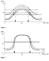
In Fig. 4 und Fig. 5 sind zwei Auslesesignale SF dargestellt, die sich auf
unterschiedliche Pitlängen (3T, 11T) bei ansonsten gleichen Parametern
beziehen. Die Signale sind als Funktion der Leserichtung für verschiedene
Pitwinkel α wiedergegeben, wobei sich der optisch aktive Bereich (Land)
zwischen den beiden Dreiecken befindet. Die Pit-Land-Struktur ist in beiden
Fällen periodisch und wurde so gewählt, daß sich ein konstanter Gleichanteil
in der Bitebene einstellt. Abweichend vom idealen Verhalten ergibt sich
in der Signalebene ein nicht konstanter Signal-Gleichanteil SG (oder Mittelwert),
der folgendermaßen definiert ist
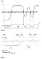
Auf einem realen Datenträger ist die Datenstruktur nicht periodisch, sondem
statistisch verteilt. Fig. 6 zeigt den Verlauf des Lesesignals SF für die
abgebildete unregelmäßige Pit-Land-Struktur. In diesem Fall resultiert der
Signal-Gleichanteil SG für DSV=0 aus der Überlagerung der Gleichanteile
aller auftretenden Signal-Komponenten für die unterschiedlichen Pit- bzw.
Landlängen, wobei die Häufigkeit für das Auftreten der verschiedenen Längen
zu berücksichtigen ist. Hierfür gilt der mathematische Zusammenhang
- I1 LT:
- Minimale auftretende Länge der Pits oder Lands
- I2 LT:
- Maximale auftretende Länge der Pits oder Lands
- LT:
- Längenstufe
- p(i):
- Wahrscheinlichkeitsdichte für das Auftreten der verschiedenen Längen i
- SFi:
- Lesesignalverlauf bei der Pit-Land-Struktur der Länge 2i LT
- I 1 L T :
- Minimum occurring length of the pits or lands
- I 2 L T :
- Maximum length of pits or lands
- L T :
- Length step
- pi):
- Probability density for the occurrence of the different lengths i
- SF i :
- Reading signal curve for the pit-land structure of length 2i L T
Beispielsweise ist bei der Compact Disc I1=3 und I2=11, wobei die typischen
Verteilungsdichten in Tabelle 1 dargestellt sind.
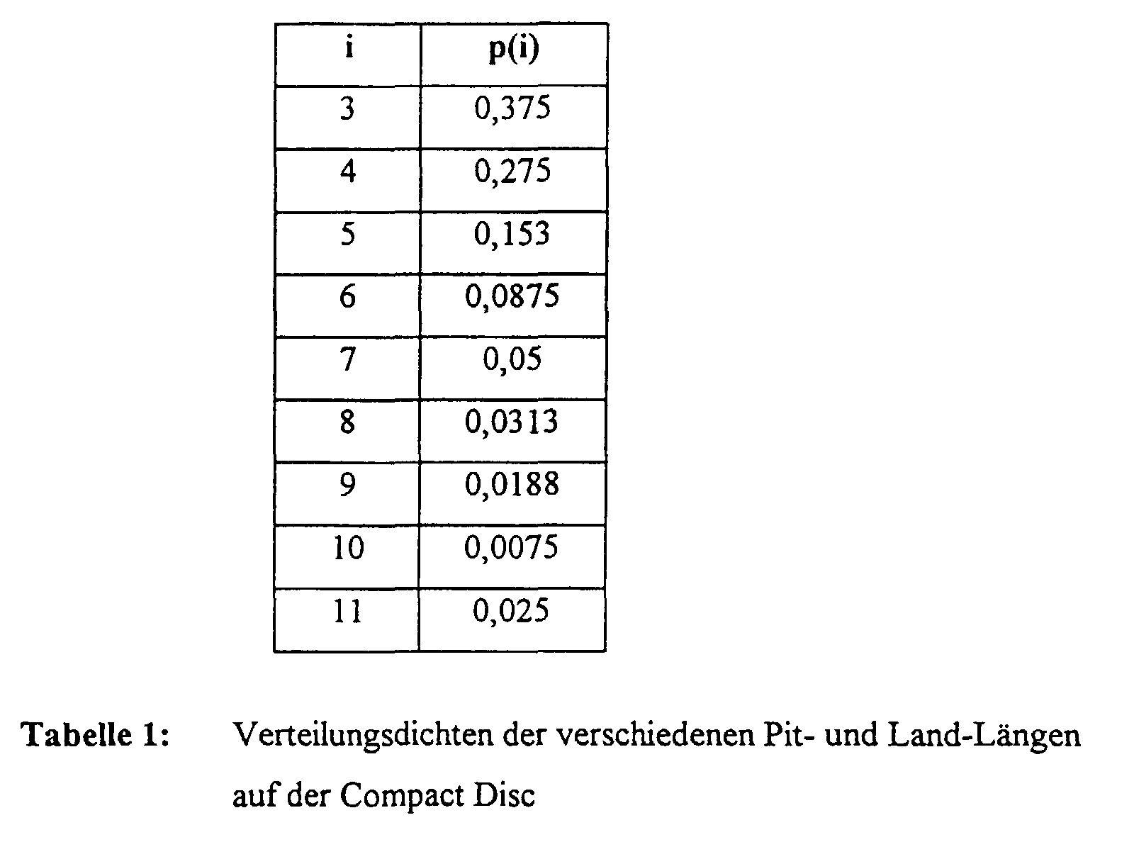
Wie aus Tab. 1 zu entnehmen ist, treten die kurzen Pits bzw. Lands erheblich
häufiger auf als die langen Pits bzw. Lands. Weiterhin ist aufgrund des
Faltungseffektes zwischen Pitstruktur und Lesestrahlgeometrie die Modulationsamplitude
des Lesesignals SF bei kurzen Pits bzw. Lands kleiner als bei
langen Pits bzw. Lands. Aufgrund dieser Tatsache beeinflussen die kurzen
bis mittleren Pits den Signal-Gleichanteil SG am stärksten, wie an dem Beispiel
aus Tab. 2 ersichtlich ist.
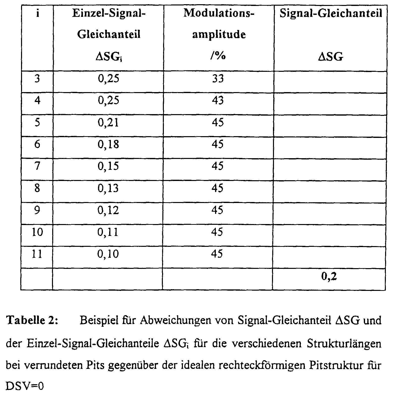
Die Einzel-Signal-Gleichanteile ΔSGi ergeben sich aus dem Lesesignal einer Folge von Pits und Lands gleicher Länge i LT. Der Signal-Gleichanteil ΔSG resultiert aus der Überlagerung aller Einzel-Signal-Gleichanteile ΔSGi unter der Berücksichtigung der Auftrittswahrscheinlichkeit.The single-signal constant components ΔSG i result from the read signal of a sequence of pits and lands of the same length i L T. The DC signal component ΔSG results from the superposition of all individual signal DC components ΔSG i , taking into account the probability of occurrence.
Tab. 2 zeigt beispielhaft die absoluten Abweichungen von Signal-Gleichanteil SG und der Einzel-Signal-Gleichanteile SGi für verschiedene Strukturlängen i bei verrundeten Pits gegenüber der idealen rechteckförmigen Pitstruktur, wobei in der zugrundeliegenden Datenebene ein DSV=0 eingestellt wurde. Wie aus dem Zahlenbeispiel in Tab. 2 erkennbar ist, liegt der Signal-Gleichanteil SG bei 0,2, während die Einzel-Signal-Gleichanteile SGi für i=3 und i=4 mit 0,25 höher angesiedelt sind. Tab. 2 shows an example of the absolute deviations of DC signal component SG and the individual signal DC component SG i for different structure lengths i for rounded pits compared to the ideal rectangular pit structure, whereby a DSV = 0 was set in the underlying data level. As can be seen from the numerical example in Table 2, the DC signal component SG is 0.2, while the individual DC signal components SG i for i = 3 and i = 4 are 0.25 higher.
In Fig. 6 wird verdeutlicht, daß gerade bei den kurzen Pits die Entscheidungsschwelle ES zur korrekten Längenbestimmung nicht übereinstimmt mit dem Gleichanteil.In Fig. 6 it is made clear that the decision threshold is precisely for the short pits ES does not match for correct length determination with the DC component.
Die obige Untersuchung zeigt, daß bei dem bekannten Verfahren durch die Festlegung des digitalen Summenwerts DSV=0 ein Signal-Gleichanteil im Dekodierer oder CD-Lesegerät entsteht, der von dem idealen Wert abweicht, so daß die im Dekodierer ermittelte Enscheidungsschwelle nicht übereinstimmt mit dem (fälschlicherweise) angenommenen idealen Signal-Gleichanteil bei DSV=0.The above investigation shows that in the known method by Determination of the digital sum value DSV = 0 a DC signal component in Decoder or CD reader is produced which deviates from the ideal value, so that the decision threshold determined in the decoder is not matches the (wrongly) assumed ideal signal component at DSV = 0.
Die obige Betrachtung zeigt darüberhinaus, daß gerade die am häufigsten auftretenden kürzeren Pitlängen (das heißt ununterbrochene Folgen von Nullen oder Einsen) mit größter Ungenauigkeit wiedergegeben werden. Dies führt aufgrund der geringen Modulationsamplitude der kürzeren Pits insbesondere in Anwesenheit von Oberflächenrauhigkeiten und produktionsbedingten Abformungsverlusten zu erhöhtem Jitter und damit zu einem Anstieg der Bitfehlerrate.The above consideration also shows that the most common shorter pit lengths that occur (i.e. uninterrupted sequences of Zeros or ones) are reproduced with the greatest inaccuracy. This leads due to the low modulation amplitude of the shorter pits especially in the presence of surface roughness and production-related Impression losses to increased jitter and thus to one Bit error rate increase.
Man kann zwar dem Modulationsverlust der kürzeren Pits durch geeignete Filter begegnen, allerdings ist diese Maßnahme mit erhöhtem Rauschen ohne nennenswerte Veränderung des Signal-Gleichanteils verbunden.One can compensate for the modulation loss of the shorter pits by suitable ones Encounter filters, but this measure is without increased noise significant change in the DC signal component connected.
Der Erfindung liegt die Aufgabe zugrunde, ein Verfahren zum Umkodieren von digitalen Informations-Datenwörtern der eingangs genannten Art anzugeben, bei dem die Bit- und damit die Datenfehlerrate im Vergleich zu dem bekannten Verfahren verringert ist.The invention has for its object a method for recoding of digital information data words of the type mentioned at the beginning, where the bit and thus the data error rate compared to the known method is reduced.
Erfindungsgemäß wird diese Aufgabe durch folgende Merkmale gelöst:
Im Gegensatz zu dem bekannten Verfahren, bei dem der minimale Signal-Gleichanteil angestrebt wird, geht die vorliegende Erfindung von der Erkenntnis aus, daß der minimale Gleichanteil in praktisch keinem Fall die optimale Entscheidungsschwelle im "Empfänger", das heißt im Dekodierer des Lesegeräts oder Abspielgeräts liefert, sondern daß die Entscheidungsschwelle einen vom minimalen Signal-Gleichanteil abweichenden Wert haben muß, wenn die kleinstmögliche Bitfehlerrate erzielt werden soll. Wie sich aus der obigen Betrachtung ergibt, liegt der einzustellende Signal-Gleichanteil und mithin die Entscheidungsschwelle im Abspielgerät anders als der minimale Signal-Gleichanteil.In contrast to the known method, in which the minimum direct signal component the present invention is based on knowledge from that the minimum DC component in practically no case the optimal decision threshold in the "receiver", ie in the decoder of the reader or player, but that the decision threshold have a value that deviates from the minimum DC signal component must if the lowest possible bit error rate is to be achieved. How results from the above consideration, the DC signal component to be set lies and therefore the decision threshold in the player is different than the minimum DC signal component.
Die Erfindung schlägt vor, bei der Umkodierung der Informations-Datenwörter in die zu speichernden oder zu übertragenden Kanaldatenwörter drauf zu achten, daß der digitale Summenwert so eingestellt wird, daß sich im Abspielgerät der günstigste Wert für die Entscheidungsschwelle ergibt. Die Erfindung nutzt dabei den Vorteil, daß im Abspielgerät, das heißt im Dekodierer, nur die Datenbits des Kanaldatenworts bezüglich der Information ausgewertet werden, nicht jedoch die redundanten Trennbits. Bei dem erfindungsgemäßen Verfahren ändert sich also für den Empfänger der Daten, das heißt im Fall der CD, für den Benutzer des CD-Abspielgeräts, praktisch nichts, nur daß er in den Genuß einer exakteren Informationswiedergabe kommt.The invention proposes in the recoding of the information data words into the channel data words to be saved or transmitted make sure that the digital total value is set so that the most favorable value for the decision threshold in the player results. The invention takes advantage of the fact that in the player that in the decoder means only the data bits of the channel data word with respect to the Information is evaluated, but not the redundant separating bits. In the method according to the invention, therefore, changes for the recipient the data, in the case of the CD, for the user of the CD player, practically nothing, except that he enjoyed a more precise Playback of information is coming.
Zur Ausführung der Erfindung sind verschiedene spezielle Maßnahmen möglich. Eine Möglichkeit besteht grundsätzlich darin, zunächst eine Tabelle zusammenzustellen, in der abhängig von den jeweiligen Parametern (Pitwinkel etc.) eine Größe für die Beziehung zwischen optimaler Entscheidungsschwelle und Signal-Gleichanteil für einen digitalen Summenwert DSV=0 erstellt wird.Various special measures are required to implement the invention possible. Basically, one possibility is to start with a table compile, depending on the respective parameters (Pit angle etc.) a variable for the relationship between the optimal decision threshold and DC signal component for a digital sum value DSV = 0 is created.
Der Signal-Gleichanteil für den Fall DSV=0 kann rein mathematisch mit den
oben angegebenen Formeln oder meßtechnisch ermittelt werden. Die tatsächliche
Entscheidungsschwelle EST kann durch Vermessung der Strukturlängen
des Datenträgers (der CD) mittels Rasterelektronenmikroskop
oder Tunnel-Rastermikroskop und Einstellung der Entscheidungsschwelle
im Hinblick auf minimale Abweichung bezüglich der vermessenen Strukturlängen
aufgefunden werden. Günstiger ist es möglicherweise, die optimale
Entscheidungsschwelle mit Hilfe eines Referenzdatenträgers mit DSV=0
und bekannter Pitform auf meßtechnischem Wege zu ermitteln, indem man
ein Referenz-Lesesystem verwendet und bei diesem die Entscheidungsschwelte
so lange variiert, bis der minimale Jitter und die minimale Bitfehlerrate
festgestellt sind. Dieser Wert wird dann als optimale Entscheidungsschwelle
EST verwendet. Man erhält beispielsweise folgende Tabelle:

In einer speziellen Ausgestaltung der Erfindung ist vorgesehen, daß die
Differenz ermittelt wird zwischen
Amax ist herbei die Maximale der Amplituden A(i) der Lesesignal-Verläufe
für unterschiedliche Strukturlängen i LT, denen die Auftrittswahrscheinlichkeitsdichten
p(i) zugeordnet sind. Die Größe dx kennzeichnet die effektive
Pitverkürzung. SG1(i) ist der Gleichanteil des Lesesignal-Verlaufs SFi1, der
einem optisch aktiven Bereich (1) der Länge iLT zugeordnet ist. SG0(i) ist
der Gleichanteil des Lesesignal-Verlaufs SFi0, der einem optisch inaktiven
Bereich (0) der Länge iLT zugeordnet ist. In Gleichung (4) ist für positive
Zuwachsraten SG1(i), für negative Zuwachsraten SG0(i) gemäß folgender
Gleichungen einzusetzen:
Die Formel (4) kann für Differenzen (EST-SG0), die hinreichend klein gegenüber
der maximal auftretenden Amplitude Amax sind, vereinfacht werden,
so daß sich unter dieser Voraussetzung ein für die Praxis einfacher zu verwendender
linearer Zusammenhang zwischen Zuwachsrate und dem resultierenden
relativen Gleichanteilanstieg einstellt:
Wird einem Datenbit vom Wert "0" der Wert B=-1 und einem Datenbit vom
Wert "1" der Wert B=I zugeordnet, so ist die Zuwachsrate in einem Datenstrom,
der das NRZ-Format nach Figur 1 aufweist, folgendermaßen definiert:
I legt hierbei das Zuwachsintervall in Bittakten fest.I defines the increment interval in bit cycles.
In einer Ausführungsform der Erfindung ist vorgesehen, daß anhand der Zuwachsrate (ZW), die dem Signal-Gleichanteil der Folge von Kanaldatenwörtern entspricht, ein maximaler digitaler Summenwert innerhalb eines vorbestimmten Zuwachsintervalls festgelegt wird, und daß innerhalb jeweils eines Zuwachsintervalls die Kanaldaten für die Kanalwörter dadurch ermittelt werden, daß für die in Frage kommenden Kombinationen von Trennbits die digitalen Summenwerte der entsprechenden Kanaldatenwörter gebildet werden und daraus jeweils die Differenz bezüglich des maximalen Summenwerts gebildet wird. Das Auswahlkriterium für die Auswahl eines Kanaldatenwort-Kandidaten ist vorzugsweise die kleinste Differenz.In one embodiment of the invention it is provided that the Growth rate (ZW), which is the signal DC component of the sequence of channel data words corresponds to a maximum digital sum value within a predetermined incremental interval is set, and that within each an increase interval determines the channel data for the channel words be that for the combinations of separating bits in question the digital sum values of the corresponding channel data words are formed and the difference with respect to the maximum total value is formed. The selection criterion for the selection of a channel data word candidate is preferably the smallest difference.
Um bei dem Verfahren die oben erwähnte d, k-Bedingung zu berücksichtigen, sieht die Erfindung vor, daß aus der Menge von Kandidaten solche Kandidaten unberücksichtigt bleiben, die im NRZI-Format nicht einer Bitfolge entsprechen, die zwischen zwei Bits "1" mindestens d und höchstens k Bits "0" aufweist. In order to take the d, k condition mentioned above into account in the method, The invention provides that from the set of candidates Candidates who are not a bit sequence in NRZI format are disregarded correspond between two bits "1" at least d and at most k Has bits "0".
In einer speziellen Ausgestaltung der Erfindung ist vorgesehen, daß der einzustellende Gleichanteil aus der Häufigkeitsverteilung der Längen aufeinanderfolgender Nullen oder Einsen errechnet wird. In die Berechnung können weitere Größen einfließen, namentlich die Lesesignalform und die effektive Pitlängenvariation.In a special embodiment of the invention it is provided that the constant component to be set from the frequency distribution of the lengths in succession Zeros or ones is calculated. In the calculation can include other variables, namely the read waveform and the effective pit length variation.
Wie bereits erwähnt, treten kürzere Pit- bzw. Land-Längen häufiger auf als längere. Aus den einzelnen Pit- bzw. Land-Längen lassen sich einzelne zugehörige Signal-Gleichanteile errechnen. Berücksichtigt man dabei noch die Wahrscheinlichkeit des Auftretens für die entsprechenden Pit-Längen, so wird der einzustellende Gleichanteil beispielsweise so festgelegt, daß er einer Entscheidungsschwelle entspricht, die zwischen den Signal-Gleichanteilen für die am häufigsten auftretenden Pit-Längen liegt. Dies wird weiter unten noch näher erläutert.As already mentioned, shorter pit or land lengths occur more often than longer. Individual associated pitches can be made from the individual pit or country lengths Calculate DC signal components. If you take that into account Probability of occurrence for the corresponding pit lengths, see above the direct component to be set is determined, for example, so that it corresponds to a decision threshold between the equal signal components for the most common pit lengths. This will be explained in more detail below.
Im folgenden wird ein Ausführungsbeispiel der Erfindung anhand der
Zeichnung näher erläutert. Es zeigen:
Als Ausführungsbeispiel soll das Verfahren zum Umwandeln von Information-Datenwörtern
in Kanaldatenwörter bei der Herstellung einer Compact
Disc (CD) erläutert werden, bei der ein Pitwinkel von α<25° gemessen
wurde, was einer effektiven Pitverkürzung dx in der Größenordnung von
100 nm entspricht. Gegenüber der idealen Pitform ergibt sich bei DSV=0
typischerweise eine relative Verschiebung des Signal-Gleichanteils
ΔSG/Amax = 0,15 gegenüber dem Signal-Gleichanteil bei idealer Pitform.
Die typische Verschiebung der auf Amax bezogenen Einzel-Gleichanteile
ΔSGi für die unterschiedlichen Strukturlängen i läßt sich der nachstehenden
Tabelle 4 entnehmen:
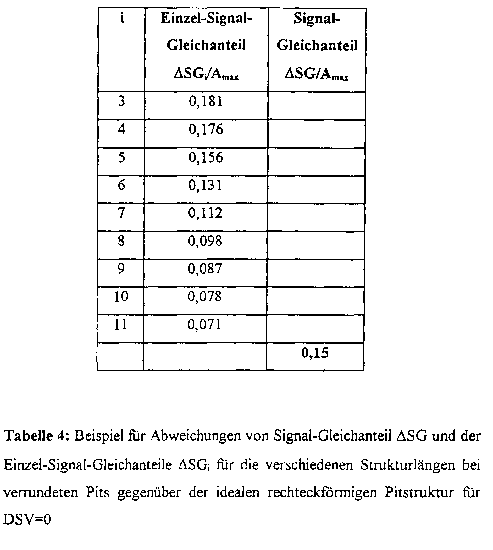
Zur Minimierung von Lesefehlern muß die tatsächliche Entscheidungsschwelle
und damit der resultierende Signal-Gleichanteil SGR an den Einzel-Gleichanteil
SGi der kurzen Pits optimal angeglichen werden. In dem
Beispiel der Tabelle 4 wird der resultierende Signal-Gleichanteil beispielsweise
zwischen SG3 und SG4 gelegt, so daß die Verschiebung des resultierenden
Signal-Gleichanteils der Einfachheit halber zu
Die relative Differenz zwischen ΔSGR und ΔSG ((0,179 - 0,15) Amax = 0,029 Amax) entspricht der Größe (EST-SG0)/Amax gemäß Tabelle 3 und gemäß Formel (4) errechnet sich ZW = - 0,058 ( =- 1/17). The relative difference between ΔSGR and ΔSG ((0.179 - 0.15) A max = 0.029 A max ) corresponds to the size (EST-SG0) / A max according to table 3 and according to formula (4), ZW = - 0.058 (= - 1/17).
Innerhalb eines Datenworts, welches eine Länge von 17 Bits aufweist, muß also eine DSV-Zuwachsrate von -1 eingestellt werden. Hierzu werden die Bits des Trennbit-Blocks in jedem Kanalwort verwendet.Within a data word that has a length of 17 bits a DSV growth rate of -1 can be set. For this, the Bits of the split bit block used in each channel word.
Die Einstellung der Zuwachsrate in einem Datenstrom soll anhand des in
Tabelle 5 wiedergegebenen Datenblocks, der im CD-Standard der digitalen
Null entspricht, erläutert werden.
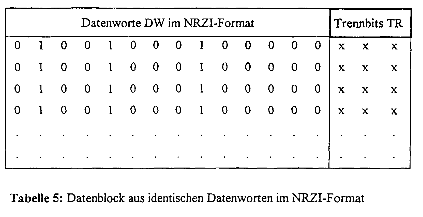
Der Datenblock, der sich beispielsweise aus identischen Datenworten zusammensetzt,
sei unbegrenzt und liegt zunächst im NRZI-Ausgangsformat
vor. Zur Übertragung wird der Datenblock um die Trennbits TR ergänzt
und in das NRZ-Format umgewandelt. Für die Zuwachsrate ZW=0,058 ist
das Ergebnis in Tab. 6 dargestellt, wobei die Wahl der Anfangs-Bit-Polarität
beliebig sein kann. In Tab. 6 wurde beispielsweise mit Bit-Polarität
1 begonnen.
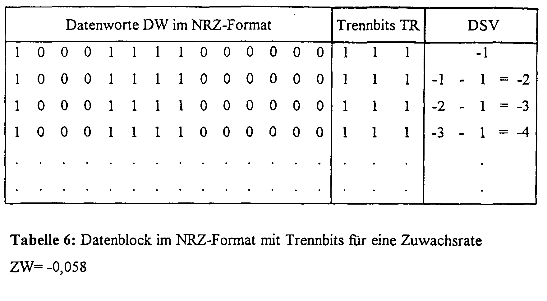
Beim Herstellungsprozeß des Datenträgers ist dafür zu sorgen, daß die "1"-wenigen Bits in Tab. 6 den relativen Maxima im Lesesignal und die "0"-wenigen Bits den relativen Minima zugeordnet sind. Wird diese Zuordnung invertiert, so wird auch fälschlicherweise die Polarität des resultierenden Signal-Gleichanteils invertiert. Aufgrund der Regelmäßigkeit in dem Datenblock aus Tab. 6 ergibt sich ein Zuwachsintervall von Tzw=17 Bittakten. Da der DSV pro Zuwachsintervall um -3+4-6+4=-1 (das sind die Bitfolgen zusammenhängender 1en und 0en) steigt, resultiert die geforderte Zuwachsrate von 1/Tzw= -1/17= -0,058.In the manufacturing process of the data carrier, care must be taken that the "1" few bits in Table 6 are assigned to the relative maxima in the read signal and the "0" few bits to the relative minima. If this assignment is inverted, the polarity of the resulting DC signal component is also incorrectly inverted. Due to the regularity in the data block from Tab. 6, there is an increase interval of T zw = 17 bit clocks. Since the DSV increases by -3 + 4-6 + 4 = -1 (these are the bit sequences of connected 1s and 0s) per growth interval, the required growth rate of 1 / T zw = -1 / 17 = -0.058 results.
Das obige Beispiel ist ein Spezialfall. Im allgemeinen Fall erstreckt sich das Zuwachsintervall über mehrere Wortlängen, also ein ganzzahliges Vielfaches von 17 Bittakten.The above example is a special case. In the general case, this extends Growth interval over several word lengths, i.e. an integer multiple of 17 bit clocks.
In dem Dekodierer (Abspielgerät) werden die empfangenen (abgetasteten) Kanalwörter dekodiert, wobei die Trennbits unberücksichtigt bleiben, was den Informationsgehalt angeht, sondern lediglich die eingangs angesprochenen Zwecke erfüllen. Die Entscheidungsschwelle wird durch Ermitteln des Signal-Gleichanteils gewonnen, was einer Aufintegration bei gleichzeitiger Division durch die Zeit entspricht. Um im Dekodierer nun die Entscheidungsschwelle, also den erfindungsgemäß gegenüber dem minimalen Gleichanteil veränderten Gleichanteil dauernd aufrecht zu erhalten, wird der digitale Summenwert DSV in den Kanaldatenwörtern laufend verändert, also erhöht oder vermindert, im dargestellten Beispiel erfolgt die Verminderung um "1" innerhalb jedes Kanaldatenworts.In the decoder (player) the received (scanned) Channel words decoded, disregarding the separator bits, what concerns the information content, but only those mentioned at the beginning Fulfill purposes. The decision threshold is determined by determining the Signal DC component gained, which is an integration at the same time Division by time. To make the decision threshold in the decoder, that is, according to the invention compared to the minimum To maintain a constant DC component, the digital total value DSV in the channel data words continuously changed, thus increased or decreased, in the example shown the reduction takes place by "1" within each channel data word.
Das Zuwachsintervall muß klein sein gegenüber den Zeitkonstanten des Lesesystems, um die Regelkreise des Lesesystems nicht zu beeinflussen. Im vorliegenden Beispiel entspricht das Zuwachsintervall einer Wortlänge des Kanaldatenworts.The growth interval must be small compared to the time constant of the Reading system in order not to influence the control loops of the reading system. in the In the present example, the growth interval corresponds to a word length of Channel data word.
Wie oben erwähnt, und wie aus der rechten Spalte in Tabelle 6 hervorgeht,
nimmt der digitale Summenwert DSV in dem Datenstrom ständig ab, da in
jedem Zuwachsintervall, im vorliegenden Beispiel also in jedem Kanaldatenwort,
der digitale Summenwert um 1 vermindert wird. Bei dem Beispiel
einer CD würde sich für den gesamten Datenstrom der Betrag des digitalen
Summenwerts auf einen extrem hohen Wert aufsummieren. Aus praktischen
Gründen wird also die Ermitttlung der digitalen Summenwerte beschränkt
auf endliche aneinandergrenzende Zuwachsintervalle, wozu eine Anzahl von
Kanaldatenwörtern, mmax gewählt wird. In der Praxis kann dieser Wert mmax
zum Beispiel bei 100 liegen, in dem weiter unten dargestellten Beispiel wird
er aus Gründen der Übersichtlichkeit auf mmax=4 festgelegt. Der Wert mmax
entspricht also der Anzahl von Kanaldatenwörtern, die maximal für die Veränderung
des digitalen Summenwerts DSV bis zum Erreichen von DSVmax
zur Verfügung steht. Dieser maximale digitale Summenwert der sowohl
positiv - bei Erhöhung des Signal-Gleichanteils - als auch negativ - bei Erniedrigung
des Signal-Gleichanteils - sein kann, steht mit dem Wert mmax
durch folgende Beziehung in Zusammenhang:
In der Gleichung (10) ergibt das Produkt aus Zuwachsrate ZW und Zuwachsintervall TZW im vorliegenden Beispiel den Wert -1, so daß der Betrag des maximalen digitalen Summenwerts DSVmax der Anzahl der Kanaldatenwörter entspricht, die für die Veränderung bis zum Erreichen von DSVmax zur Verfügung steht. Bei einer geringeren Zuwachsrate ZW und gleichem Zuwachsintervall (hier: 17 Bittakte) müßte mmax bei gleichem Wert von DSVmax erhöht werden.In the equation (10), the product of the growth rate ZW and the growth interval T ZW in the present example gives the value -1, so that the amount of the maximum digital sum value DSV max corresponds to the number of channel data words which are required for the change until DSV max is reached is available. With a lower growth rate ZW and the same growth interval (here: 17 bit clocks), m max would have to be increased with the same value of DSV max .
Figur 7 zeigt den Anfang des Datenstroms, der aus Informations-Datenwörtern durch Einfügen von Trennbit-Blöcken erhalten wurde. Der Wert mmax ist hier auf 4 festgelegt. Ein Kanaldatenwort CW besteht aus jeweils einem Datenwort mit 14 Bits und einem Trennbit-Block TR, der drei Bits enthält.FIG. 7 shows the beginning of the data stream which was obtained from information data words by inserting separating bit blocks. The value m max is set to 4 here. A channel data word CW consists of a data word with 14 bits and a separating bit block TR which contains three bits.
Für das im folgenden anhand der Figur 8 erläuterte Verfahren zum Einstellen des veränderten Signal-Gleichanteils wird der Indexzähler i eingeführt. Er wird nach jedem 4 Kanaldatenwörter umfassenden Abschnitt um 1 erhöht. Der Index m wird zyklisch von 0 auf 3 erhöht, da der maximale Wert für den Abschnitt von Kanaldatenwörtern bis zum Erreichen von DSVmax hier auf 4 festgelegt wurde. Unten in Figur 7 ist der von i und m abhängige Index des jeweiligen Kanaldatenworts CW angegeben. Bei i=2 und m=2 ergibt sich nach dem angegebenen Index das Kanaldatenwort CW6 (4·1+ 2=6).The index counter i is introduced for the method for setting the changed DC signal component explained below with reference to FIG. 8. It is increased by 1 after each section comprising 4 channel data words. The index m is increased cyclically from 0 to 3, since the maximum value for the section of channel data words up to DSV max was set to 4 here. The index of the respective channel data word CW, which is dependent on i and m, is given at the bottom in FIG. With i = 2 and m = 2, the channel data word CW 6 (4 · 1 + 2 = 6) results from the specified index.
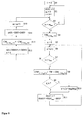
In dem in Figur 8 dargestellten Ablauf wird im Schritt S1 zunächst der in Figur 7 dargestellte Indexzähler i auf Null gesetzt.In the sequence shown in FIG. 8, the step in Figure 7 index counter i set to zero.
Im Schritt S2 wird der digitale Summenwert DSV auf 0 gesetzt, und auch der zyklisch durchlaufende Wert von m innerhalb der maximalen Anzahl mmax von zur Veränderung von DSV zur Verfügung stehenden Kanaldatenwörtern wird auf 0 gesetzt. Der Indexzähler i wird um 1 erhöht, also im ersten Durchlauf auf den Wert 1 gesetzt.In step S2, the digital sum value DSV is set to 0, and the cyclically running value of m within the maximum number m max of channel data words available for changing DSV is also set to 0. The index counter i is increased by 1, i.e. set to 1 in the first pass.
Bei Erreichen des Entscheidungsschritts S3 ist (wegen m=0) die Bedingung JA erfüllt.When decision step S3 is reached (because of m = 0) the condition is YES fulfilled.
Deshalb wird im Schritt S4 das dem angegebenen Index entsprechende Datenwort geholt, im vorliegenden Beispiel also das Datenwort DW0, das erste Datenwort in dem hier betrachteten Datenstrom. Therefore, in step S4, the data word corresponding to the specified index is fetched, in the present example, data word DW 0 , the first data word in the data stream considered here.
Im nachfolgenden Schritt S5 wird ein Indexzähler n auf 0 gesetzt. Der Indexzähler n wird in der nachfolgenden Schleife laufend um jeweils 1 erhöht bis auf den Wert n=7, da bei drei Trennbits insgesamt nmax=8 Bitkombinationen möglich sind.In the subsequent step S5, an index counter n is set to 0. The index counter n is continuously increased in the following loop by 1 to the value n = 7, since a total of n max = 8 bit combinations are possible with three separating bits.
Nach Erhöhung des Indexzählers n im Schritt S6 und der Entscheidung JA im Entscheidungsschritt S7 wird für den Wert n (beim ersten Durchlauf also n=0) das im Schritt S4 geholte Datenwort ergänzt, so daß sich ein Kanaldatenwort (mit 17 Bits) entsprechend dem durch i und m festgelegten Index ergibt.After the index counter n has been increased in step S6 and the decision YES in decision step S7, the value n is (for the first pass, that is n = 0) supplements the data word fetched in step S4, so that there is a channel data word (with 17 bits) according to the index defined by i and m results.
In den Schritten S9 und S10 wird geprüft, ob das Kanaldatenwort, welches im Schritt S8 gebildet wurde, der d, k-Bedingung genügt. Diese Bedingung wurde oben erläutert. Die Schritte S9 und S10 sondern solche Kanaldatenwörter aus, die der d, k-Bedingung nicht genügen.In steps S9 and S10 it is checked whether the channel data word which was formed in step S8, the d, k condition is satisfied. This condition was explained above. Steps S9 and S10 separate such channel data words that do not meet the d, k condition.
Im Schritt S11 wird der zu dem laufenden Index n gehörige digitale Summenwert abgefragt. Dieser digitale Summenwert hängt ab von dem Datenwort und dem diesem hinzugefügten Trennbit-Block entsprechend dem Schritt S8. Außerdem wird im Schrift S11 der Differenzwert DDSVn zwischen DSVmax und dem zuvor ermittelten digitalen Summenwert DSVn ermittelt. Bei drei Trennbits wird diese Schleife mit den Schritten S6-S11 also achtmal durchlaufen, so daß aus dem Schritt S11 sich achtmal ein Differenzwert DDSVn ergibt.In step S11, the digital sum value belonging to the current index n is queried. This digital sum value depends on the data word and the separating bit block added to it in accordance with step S8. In addition, the difference value DDSV n between DSV max and the previously determined digital total value DSV n is determined in font S11. With three separating bits, this loop is therefore run through eight times with steps S6-S11, so that a difference value DDSV n results from step S11 eight times.
Nach dem letzten Durchlauf erfolgt aus dem Schritt S7 ein Übergang zum Schritt S12. Hier wird der kleinste aufgefündene Differenzwert aus den vorausgehenden mehrmaligen Berechnungen entsprechend dem Schritt S11 ermittelt und mit Hilfe eines Index j wird im Schritt S13 das Kanalwort CWj von den 8 im Schritt S8 gebildeten Kanalwörtern ausgewählt, welches dem kleinsten Differenzwert entspricht. Dieses Kanalwort wird dann im Fall des vorliegenden Beispiels auf der Compact Disc erzeugt. After the last run, step S7 proceeds to step S12. Here, the smallest difference value found is determined from the preceding multiple calculations in accordance with step S11 and with the aid of an index j, the channel word CW j is selected in step S13 from the 8 channel words formed in step S8, which corresponds to the smallest difference value. This channel word is then generated on the compact disc in the case of the present example.
Im nachfolgenden Schritt S14 erfolgt die Erhöhung oder Akkumulation des laufenden digitalen Summenwerts DSV um den digitalen Summenwert, der der zuvor aufgefündenen kleinsten Differenz gemäß Schritt S11 entspricht.In the subsequent step S14, the increase or accumulation of the running digital sum value DSV around the digital sum value, the corresponds to the previously found smallest difference in step S11.
Mit anderen Worten: der im Schritt S14 hinzuaddierte Wert DSVj entspricht dem im Betrag maximalen gültigen (n≠x) digitalen Summenwert, der in den letzten acht Durchläufen der Schleife der Schritte S6-S11 aufgeführt wurde.In other words, the value DSV j added in step S14 corresponds to the maximum digital (n ≠ x) digital sum value that was specified in the last eight passes of the loop in steps S6-S11.
Dann wird der Zähler m im Schritt S15 um 1 erhöht, ist der Zähler m noch kleiner als der Wert mmax (im vorliegenden Beispiel kleiner als 4), so wird die Schleife mit den Schritten S3-S15 noch einmal durchlaufen, wobei die Schleife mit den Schritten S6-S11 (m=8)-mal durchlaufen wird. Schließlich ist man bei dem Wert mmax angelangt, in Figur 7 also bei dem Kanaldatenwort CW3. Dies führt durch die Antwort NEIN im Schritt S3 den Ablauf erneut zum Schritt S2, in welchem der Indexzähler i um 1 erhöht wird, was einem Übergang zu den rechts in Figur 7 dargestellten Kanaldatenwörtern CW4 bis CW7 entsprechend dem Indexzähler i=2 entspricht.Then the counter m is incremented by 1 in step S15, if the counter m is still smaller than the value m max (in the present example less than 4), the loop with steps S3-S15 is run through again, the loop with steps S6-S11 (m = 8) times. Finally, the value m max has been reached , that is to say the channel data word CW 3 in FIG. 7. With the answer NO in step S3, this again leads to step S2, in which the index counter i is increased by 1, which corresponds to a transition to the channel data words CW 4 to CW 7 shown on the right in FIG. 7, corresponding to the index counter i = 2.
Wie aus dem oben beschriebenen Ablauf des Prozesses zum Einstellen des veränderten Signal-Gleichanteils hervorgeht, kann es zum Beispiel vorkommen, daß beim erstmaligen Festlegen eines Kanaldatenworts im Schritt S13 ein Kanaldatenwort ausgewählt wird, welches einem sehr großen digitalen Summenwert entspricht, der im Schritt S11 ermittelt wurde. Wenn der Wert DSVn im Schritt S11 nahezu so groß ist wie der Schritt DSVmax, so ergibt sich eine entsprechend kleine Differenz DDSVn. Der im Schritt S14 dann durch Aufsummierung erhaltene Wert DSV liegt dann in der Nähe des Werts DSVmax, so daß die nachfolgend ausgewählten Kanalworte nur einen geringen Zuwachs des digitalen Summenwerts aufweist.As can be seen from the above-described sequence of the process for setting the changed DC signal component, it can happen, for example, that when a channel data word is first set in step S13, a channel data word is selected which corresponds to a very large digital sum value which is determined in step S11 has been. If the value DSV n in step S11 is almost as large as step DSV max , there is a correspondingly small difference DDSV n . The value DSV then obtained in step S14 by summation is then close to the value DSV max , so that the subsequently selected channel words have only a slight increase in the digital sum value.
Wie bereits eingangs erläutert, ist das hier vorgestellte Verfahren zum Festlegen einer Entscheidungsschwelle bei der Übertragung oder Zwischenspeicherung von digitalen Informations-Datenwörtern grundsätzlich bei sämtlichen Speicher- und Übertragungsverfahren anwendbar, wenn bei diesen Verfahren nachweisbar ist, daß die optimale Entscheidungsschwelle abweicht von derjenigen Entscheidungsschwelle, die dem minimalen Signal-Gleichanteil entspricht.As already explained at the beginning, the method presented here is for setting a decision threshold when transferring or caching of digital information data words in principle for all Storage and transmission procedures applicable if applicable to these It can be demonstrated that the optimal decision threshold differs from the decision threshold that corresponds to the minimum DC signal component corresponds.
Ein wesentlicher Vorteil des beschriebenen Verfahrens ist es, daß das Auslesesystem in seinem Aufbau nicht verändert werden muß, da die Trennbits bei der Datenauswertung eliminiert werden und somit, bis auf die gewünschte Verschiebung des Signal-Gleichanteils, keine Auswirkung auf die weitere Datenverarbeitung im Gerät haben.A major advantage of the method described is that the readout system its structure does not have to be changed since the separating bits be eliminated in the data evaluation and thus, except for the desired one Shift of the DC signal component, no effect on the have further data processing in the device.
Das Verfahren ist nicht auf den beschriebenen Fall der Compact Disc beschränkt, sondern kann auf äquivalente Datenträger, die die Einstellung einer Zuwachsrate im DSV erlauben, angewendet werden.The procedure is not limited to the compact disc case described, but can be on equivalent disks that have the setting allow a growth rate in the DSV to be applied.
So sind zum Beispiel Aufzeichnungssysteme wie Digital Versatile Disc (DVD) bekannt, bei denen jedem n1-Bit langem Informations-Datenwort eine bestimmte Anzahl unterschiedlicher n2-Bit langer Kanaldatenworte, die in ihrer Bedeutung gleichwertig sind und die geforderten Kanalbedingungen erfüllen, zugeordnet werden können. Das heißt, der Kodierer kann eine Auswahl aus den möglichen Kanaldatenworten so treffen, daß eine geforderte Zuwachsrate einstellbar ist. Der Ablauf zur Einstellung der Zuwachsrate bei einem derartigen System ist dem in Figur 8 dargestellten Aufbau äquivalent. Im Auslesesystem wird dann jedem Kanaldatenwort aus der bestimmten Anzahl von unterschiedlichen, gleichbedeutenden, n2-Bit langen Kanaldatenwörtern wieder ein einziges Informations-Datenwort zugeordnet.Thus, for example, recording systems such as D igital V ersatile D isc (DVD) are known in which each of n 1-bit long information data word fulfill a certain number of different n 2 -bit long channel data words which are equivalent in their significance and the required channel conditions , can be assigned. This means that the encoder can make a selection from the possible channel data words in such a way that a required growth rate can be set. The procedure for setting the growth rate in such a system is equivalent to the structure shown in FIG. In the readout system, a single information data word is then again assigned to each channel data word from the specific number of different, equivalent, n 2 -bit long channel data words.
Claims (9)
gekennzeichnet durch folgende Merkmale;
characterized by the following features;
daß eine Zuwachsrate (ZW) für den digitalen Summenwert (DSV) gemäß der Formel
that a growth rate (ZW) for the digital total value (DSV) according to the formula
Priority Applications (4)
| Application Number | Priority Date | Filing Date | Title |
|---|---|---|---|
| EP19980117843 EP0991069B1 (en) | 1998-09-15 | 1998-09-21 | Method and apparatus for coding digital information data and recording medium with structure of information obtained with that method |
| DE19981844T DE19981844D2 (en) | 1998-09-15 | 1999-09-14 | Method and device for recoding digital information data words and record carriers with an information structure generated according to this method |
| AU58634/99A AU5863499A (en) | 1998-09-15 | 1999-09-14 | Method and device for recoding digital information data words and a recording medium comprising an information structure according to said method |
| PCT/EP1999/006808 WO2000016327A1 (en) | 1998-09-15 | 1999-09-14 | Method and device for recoding digital information data words and a recording medium comprising an information structure according to said method |
Applications Claiming Priority (3)
| Application Number | Priority Date | Filing Date | Title |
|---|---|---|---|
| EP98117505 | 1998-09-15 | ||
| EP98117505 | 1998-09-15 | ||
| EP19980117843 EP0991069B1 (en) | 1998-09-15 | 1998-09-21 | Method and apparatus for coding digital information data and recording medium with structure of information obtained with that method |
Publications (2)
| Publication Number | Publication Date |
|---|---|
| EP0991069A1 true EP0991069A1 (en) | 2000-04-05 |
| EP0991069B1 EP0991069B1 (en) | 2001-03-28 |
Family
ID=26149637
Family Applications (1)
| Application Number | Title | Priority Date | Filing Date |
|---|---|---|---|
| EP19980117843 Expired - Lifetime EP0991069B1 (en) | 1998-09-15 | 1998-09-21 | Method and apparatus for coding digital information data and recording medium with structure of information obtained with that method |
Country Status (4)
| Country | Link |
|---|---|
| EP (1) | EP0991069B1 (en) |
| AU (1) | AU5863499A (en) |
| DE (1) | DE19981844D2 (en) |
| WO (1) | WO2000016327A1 (en) |
Citations (8)
| Publication number | Priority date | Publication date | Assignee | Title |
|---|---|---|---|---|
| DE3125529A1 (en) * | 1980-07-14 | 1982-05-13 | Naamloze Vennootschap Philips' Gloeilampenfabrieken, 5621 Eindhoven | "METHOD FOR RECODING A SEQUENCE OF DATA BITS INTO A SEQUENCE OF CHANNEL BITS, ARRANGEMENT FOR DECODING THE CHANNEL BITS ENCODED BY THIS METHOD AND RECORDING MEDIUM WITH AN INFORMATION STRUCTURE" |
| US4539691A (en) * | 1981-09-11 | 1985-09-03 | Sony Corporation | Method and apparatus for encoding a binary digital information signal |
| EP0396346A1 (en) * | 1989-04-28 | 1990-11-07 | Canon Kabushiki Kaisha | Error check or error correction code coding device |
| US5469162A (en) * | 1992-03-31 | 1995-11-21 | Sony Corporation | Data modulation method |
| EP0691750A1 (en) * | 1994-07-08 | 1996-01-10 | Victor Company Of Japan, Limited | Digital modulating/demodulating method and apparatus using same |
| US5508701A (en) * | 1993-07-06 | 1996-04-16 | Mitsubishi Denki Kabushiki Kaisha | Data conversion method and recording and reproduction apparatus |
| US5627694A (en) * | 1992-02-19 | 1997-05-06 | Mitsubishi Denki Kabushiki Kaisha | Recording/reproducing apparatus for recording and reproducing multiple kinds of digital signals having different data amounts per unit time |
| US5742243A (en) * | 1995-02-20 | 1998-04-21 | Pioneer Electric Corporation | Method and apparatus for reducing DC component of RLL codes |
-
1998
- 1998-09-21 EP EP19980117843 patent/EP0991069B1/en not_active Expired - Lifetime
-
1999
- 1999-09-14 DE DE19981844T patent/DE19981844D2/en not_active Expired - Fee Related
- 1999-09-14 WO PCT/EP1999/006808 patent/WO2000016327A1/en not_active Ceased
- 1999-09-14 AU AU58634/99A patent/AU5863499A/en not_active Abandoned
Patent Citations (8)
| Publication number | Priority date | Publication date | Assignee | Title |
|---|---|---|---|---|
| DE3125529A1 (en) * | 1980-07-14 | 1982-05-13 | Naamloze Vennootschap Philips' Gloeilampenfabrieken, 5621 Eindhoven | "METHOD FOR RECODING A SEQUENCE OF DATA BITS INTO A SEQUENCE OF CHANNEL BITS, ARRANGEMENT FOR DECODING THE CHANNEL BITS ENCODED BY THIS METHOD AND RECORDING MEDIUM WITH AN INFORMATION STRUCTURE" |
| US4539691A (en) * | 1981-09-11 | 1985-09-03 | Sony Corporation | Method and apparatus for encoding a binary digital information signal |
| EP0396346A1 (en) * | 1989-04-28 | 1990-11-07 | Canon Kabushiki Kaisha | Error check or error correction code coding device |
| US5627694A (en) * | 1992-02-19 | 1997-05-06 | Mitsubishi Denki Kabushiki Kaisha | Recording/reproducing apparatus for recording and reproducing multiple kinds of digital signals having different data amounts per unit time |
| US5469162A (en) * | 1992-03-31 | 1995-11-21 | Sony Corporation | Data modulation method |
| US5508701A (en) * | 1993-07-06 | 1996-04-16 | Mitsubishi Denki Kabushiki Kaisha | Data conversion method and recording and reproduction apparatus |
| EP0691750A1 (en) * | 1994-07-08 | 1996-01-10 | Victor Company Of Japan, Limited | Digital modulating/demodulating method and apparatus using same |
| US5742243A (en) * | 1995-02-20 | 1998-04-21 | Pioneer Electric Corporation | Method and apparatus for reducing DC component of RLL codes |
Non-Patent Citations (3)
| Title |
|---|
| ANONYMOUS: "Charge Constrained Byte Oriented (0,3) Code. December 1976.", IBM TECHNICAL DISCLOSURE BULLETIN, vol. 19, no. 7, December 1976 (1976-12-01), New York, US, pages 2715 - 2717, XP002088647 * |
| SEEHAUSEN G.: "influence of pit geometry on read-out signals of optical data disc drives", IEEE INTERNATIONAL PUBLICATION, (LONDON) ELECTRONICS LETTERS, vol. 28, no. 18, August 1992 (1992-08-01), pages 1709 - 1711, XP002088646 * |
| TANG D T ET AL: "Block codes for a class of constrained noiseless channels", INFORMATION AND CONTROL, DEC. 1970, USA, vol. 17, no. 5, ISSN 0019-9958, pages 436 - 461, XP002088712 * |
Also Published As
| Publication number | Publication date |
|---|---|
| AU5863499A (en) | 2000-04-03 |
| EP0991069B1 (en) | 2001-03-28 |
| DE19981844D2 (en) | 2001-06-21 |
| WO2000016327A1 (en) | 2000-03-23 |
Similar Documents
| Publication | Publication Date | Title |
|---|---|---|
| DE69117035T2 (en) | Digital modulation | |
| DE3125529C2 (en) | Method for recoding a sequence of data bits into a sequence of channel bits, arrangement for decoding the channel bits coded according to this method and recording medium with an information structure generated according to this method | |
| DE69614458T2 (en) | Optical data storage medium | |
| DE69714790T2 (en) | Optical disk, optical disk device and method for reproducing information on the optical disk | |
| DE60133329T2 (en) | Record additional data with connecting frames and different synchronization signals | |
| EP0612156B1 (en) | Digital coding method | |
| DE69319997T2 (en) | Modulation method, modulation device and demodulation device | |
| DE69421464T2 (en) | Optical recording medium, method for recording information signals recorded on the recording medium and device for data recording for the production of the optical recording medium | |
| DE69131142T2 (en) | Data recording and playback device | |
| DE3852186T2 (en) | Method for formatting a disc, method for reading and writing on a disc so formatted, disc drive with a disc so formatted and disc so formatted. | |
| DE69327740T2 (en) | Method and device for modulation and demodulation | |
| DE69612955T4 (en) | METHOD FOR CONVERTING M-BIT INFORMATION WORDS IN A MODULAR SIGNAL, METHOD FOR PRODUCING A RECORDING TRAY, CODING DEVICE, DEVICE, RECORDING DEVICE, SIGNAL, AND RECORDING CARRIER | |
| DE69522650T2 (en) | SIGNAL MODULATION AND DEMODULATION METHOD AND DEVICE | |
| DE69321746T2 (en) | Data modulation and demodulation method and device | |
| DE69614338T2 (en) | Optical information recording medium | |
| CH662202A5 (en) | METHOD FOR RECORDING A BINARY INFORMATION SIGNAL ON A RECORDING CARRIER WITH A RADIO-SENSITIVE INFORMATION LAYER. | |
| DE69700462T2 (en) | Device and method for recording information | |
| DE2828219C2 (en) | ||
| DE3122755A1 (en) | "METHOD FOR ENCODING DATA BITS ON A RECORDING CARRIER, ARRANGEMENT FOR IMPLEMENTING THE METHOD, AND RECORDING CARRIER WITH AN INFORMATION STRUCTURE" | |
| DE3434418C2 (en) | ||
| DE69426482T2 (en) | Method for producing an optical information carrier, device for carrying out the method, and optical information carrier produced by this method | |
| DE2637963A1 (en) | METHOD AND DEVICE FOR THE RECORDING OF DIGITAL DATA ON A MAGNETIC TAPE | |
| DE2430685A1 (en) | METHOD AND DEVICE FOR FAST DIGITAL MODULATION | |
| DE69212027T2 (en) | Method and device for digital modulation | |
| DE69626244T2 (en) | Binary coding of signals and digital signal processing |
Legal Events
| Date | Code | Title | Description |
|---|---|---|---|
| PUAI | Public reference made under article 153(3) epc to a published international application that has entered the european phase |
Free format text: ORIGINAL CODE: 0009012 |
|
| 17P | Request for examination filed |
Effective date: 19980921 |
|
| AK | Designated contracting states |
Kind code of ref document: A1 Designated state(s): AT BE CH CY DE DK ES FI FR GB GR IE IT LI LU MC NL PT SE |
|
| AX | Request for extension of the european patent |
Free format text: AL;LT;LV;MK;RO;SI |
|
| GRAG | Despatch of communication of intention to grant |
Free format text: ORIGINAL CODE: EPIDOS AGRA |
|
| GRAG | Despatch of communication of intention to grant |
Free format text: ORIGINAL CODE: EPIDOS AGRA |
|
| GRAH | Despatch of communication of intention to grant a patent |
Free format text: ORIGINAL CODE: EPIDOS IGRA |
|
| AKX | Designation fees paid |
Free format text: AT BE CH CY DE DK ES FI FR GB GR IE IT LI LU MC NL PT SE |
|
| AXX | Extension fees paid |
Free format text: AL PAYMENT 20000926;LT PAYMENT 20000926;LV PAYMENT 20000926;MK PAYMENT 20000926;RO PAYMENT 20000926;SI PAYMENT 20000926 |
|
| GRAH | Despatch of communication of intention to grant a patent |
Free format text: ORIGINAL CODE: EPIDOS IGRA |
|
| GRAA | (expected) grant |
Free format text: ORIGINAL CODE: 0009210 |
|
| AK | Designated contracting states |
Kind code of ref document: B1 Designated state(s): AT BE CH CY DE DK ES FI FR GB GR IE IT LI LU MC NL PT SE |
|
| AX | Request for extension of the european patent |
Free format text: AL PAYMENT 20000926;LT PAYMENT 20000926;LV PAYMENT 20000926;MK PAYMENT 20000926;RO PAYMENT 20000926;SI PAYMENT 20000926 |
|
| PG25 | Lapsed in a contracting state [announced via postgrant information from national office to epo] |
Ref country code: NL Free format text: LAPSE BECAUSE OF FAILURE TO SUBMIT A TRANSLATION OF THE DESCRIPTION OR TO PAY THE FEE WITHIN THE PRESCRIBED TIME-LIMIT Effective date: 20010328 Ref country code: IT Free format text: LAPSE BECAUSE OF FAILURE TO SUBMIT A TRANSLATION OF THE DESCRIPTION OR TO PAY THE FEE WITHIN THE PRE;WARNING: LAPSES OF ITALIAN PATENTS WITH EFFECTIVE DATE BEFORE 2007 MAY HAVE OCCURRED AT ANY TIME BEFORE 2007. THE CORRECT EFFECTIVE DATE MAY BE DIFFERENT FROM THE ONE RECORDED.SCRIBED TIME-LIMIT Effective date: 20010328 Ref country code: IE Free format text: LAPSE BECAUSE OF FAILURE TO SUBMIT A TRANSLATION OF THE DESCRIPTION OR TO PAY THE FEE WITHIN THE PRESCRIBED TIME-LIMIT Effective date: 20010328 Ref country code: GB Free format text: LAPSE BECAUSE OF FAILURE TO SUBMIT A TRANSLATION OF THE DESCRIPTION OR TO PAY THE FEE WITHIN THE PRESCRIBED TIME-LIMIT Effective date: 20010328 Ref country code: FR Free format text: LAPSE BECAUSE OF FAILURE TO SUBMIT A TRANSLATION OF THE DESCRIPTION OR TO PAY THE FEE WITHIN THE PRESCRIBED TIME-LIMIT Effective date: 20010328 Ref country code: FI Free format text: LAPSE BECAUSE OF FAILURE TO SUBMIT A TRANSLATION OF THE DESCRIPTION OR TO PAY THE FEE WITHIN THE PRESCRIBED TIME-LIMIT Effective date: 20010328 Ref country code: CY Free format text: LAPSE BECAUSE OF NON-PAYMENT OF DUE FEES Effective date: 20010328 |
|
| REF | Corresponds to: |
Ref document number: 200160 Country of ref document: AT Date of ref document: 20010415 Kind code of ref document: T |
|
| REG | Reference to a national code |
Ref country code: CH Ref legal event code: EP |
|
| REG | Reference to a national code |
Ref country code: IE Ref legal event code: FG4D Free format text: GERMAN |
|
| REF | Corresponds to: |
Ref document number: 59800578 Country of ref document: DE Date of ref document: 20010503 |
|
| PG25 | Lapsed in a contracting state [announced via postgrant information from national office to epo] |
Ref country code: SE Free format text: LAPSE BECAUSE OF FAILURE TO SUBMIT A TRANSLATION OF THE DESCRIPTION OR TO PAY THE FEE WITHIN THE PRESCRIBED TIME-LIMIT Effective date: 20010628 Ref country code: PT Free format text: LAPSE BECAUSE OF FAILURE TO SUBMIT A TRANSLATION OF THE DESCRIPTION OR TO PAY THE FEE WITHIN THE PRESCRIBED TIME-LIMIT Effective date: 20010628 Ref country code: DK Free format text: LAPSE BECAUSE OF FAILURE TO SUBMIT A TRANSLATION OF THE DESCRIPTION OR TO PAY THE FEE WITHIN THE PRESCRIBED TIME-LIMIT Effective date: 20010628 |
|
| PG25 | Lapsed in a contracting state [announced via postgrant information from national office to epo] |
Ref country code: GR Free format text: LAPSE BECAUSE OF FAILURE TO SUBMIT A TRANSLATION OF THE DESCRIPTION OR TO PAY THE FEE WITHIN THE PRESCRIBED TIME-LIMIT Effective date: 20010629 |
|
| EN | Fr: translation not filed | ||
| NLV1 | Nl: lapsed or annulled due to failure to fulfill the requirements of art. 29p and 29m of the patents act | ||
| PG25 | Lapsed in a contracting state [announced via postgrant information from national office to epo] |
Ref country code: MC Free format text: LAPSE BECAUSE OF NON-PAYMENT OF DUE FEES Effective date: 20010921 Ref country code: LU Free format text: LAPSE BECAUSE OF NON-PAYMENT OF DUE FEES Effective date: 20010921 Ref country code: AT Free format text: LAPSE BECAUSE OF NON-PAYMENT OF DUE FEES Effective date: 20010921 |
|
| GBV | Gb: ep patent (uk) treated as always having been void in accordance with gb section 77(7)/1977 [no translation filed] |
Effective date: 20010328 |
|
| PG25 | Lapsed in a contracting state [announced via postgrant information from national office to epo] |
Ref country code: ES Free format text: LAPSE BECAUSE OF FAILURE TO SUBMIT A TRANSLATION OF THE DESCRIPTION OR TO PAY THE FEE WITHIN THE PRESCRIBED TIME-LIMIT Effective date: 20010927 |
|
| PG25 | Lapsed in a contracting state [announced via postgrant information from national office to epo] |
Ref country code: BE Free format text: LAPSE BECAUSE OF NON-PAYMENT OF DUE FEES Effective date: 20010930 |
|
| REG | Reference to a national code |
Ref country code: IE Ref legal event code: FD4D |
|
| PLBE | No opposition filed within time limit |
Free format text: ORIGINAL CODE: 0009261 |
|
| STAA | Information on the status of an ep patent application or granted ep patent |
Free format text: STATUS: NO OPPOSITION FILED WITHIN TIME LIMIT |
|
| 26N | No opposition filed | ||
| BERE | Be: lapsed |
Owner name: SEEHAUSEN GERHARD Effective date: 20010930 |
|
| PG25 | Lapsed in a contracting state [announced via postgrant information from national office to epo] |
Ref country code: LI Free format text: LAPSE BECAUSE OF NON-PAYMENT OF DUE FEES Effective date: 20020930 Ref country code: CH Free format text: LAPSE BECAUSE OF NON-PAYMENT OF DUE FEES Effective date: 20020930 |
|
| REG | Reference to a national code |
Ref country code: CH Ref legal event code: PL |
|
| PGFP | Annual fee paid to national office [announced via postgrant information from national office to epo] |
Ref country code: DE Payment date: 20051125 Year of fee payment: 8 |
|
| PG25 | Lapsed in a contracting state [announced via postgrant information from national office to epo] |
Ref country code: DE Free format text: LAPSE BECAUSE OF NON-PAYMENT OF DUE FEES Effective date: 20070403 |