EP0989897B1 - Bar screen basket for fiber suspensions and method for the production thereof - Google Patents
Bar screen basket for fiber suspensions and method for the production thereof Download PDFInfo
- Publication number
- EP0989897B1 EP0989897B1 EP98934957A EP98934957A EP0989897B1 EP 0989897 B1 EP0989897 B1 EP 0989897B1 EP 98934957 A EP98934957 A EP 98934957A EP 98934957 A EP98934957 A EP 98934957A EP 0989897 B1 EP0989897 B1 EP 0989897B1
- Authority
- EP
- European Patent Office
- Prior art keywords
- screen
- profiled
- bars
- profiled bar
- profiled bars
- Prior art date
- Legal status (The legal status is an assumption and is not a legal conclusion. Google has not performed a legal analysis and makes no representation as to the accuracy of the status listed.)
- Expired - Lifetime
Links
- 239000000835 fiber Substances 0.000 title claims abstract description 46
- 239000000725 suspension Substances 0.000 title claims abstract description 43
- 238000004519 manufacturing process Methods 0.000 title claims description 17
- 238000000034 method Methods 0.000 title claims description 15
- 239000000463 material Substances 0.000 claims abstract description 31
- 238000006073 displacement reaction Methods 0.000 claims abstract description 15
- 230000001154 acute effect Effects 0.000 claims description 5
- 230000004323 axial length Effects 0.000 claims description 4
- 239000011324 bead Substances 0.000 claims description 2
- 230000002093 peripheral effect Effects 0.000 abstract description 6
- 239000002184 metal Substances 0.000 abstract description 2
- 238000013461 design Methods 0.000 description 6
- 238000005452 bending Methods 0.000 description 5
- 238000010438 heat treatment Methods 0.000 description 5
- 230000008569 process Effects 0.000 description 3
- 235000001674 Agaricus brunnescens Nutrition 0.000 description 2
- 230000035508 accumulation Effects 0.000 description 2
- 238000009825 accumulation Methods 0.000 description 2
- 230000002776 aggregation Effects 0.000 description 2
- 230000008901 benefit Effects 0.000 description 2
- 230000008859 change Effects 0.000 description 2
- 238000003825 pressing Methods 0.000 description 2
- 238000005096 rolling process Methods 0.000 description 2
- 238000003466 welding Methods 0.000 description 2
- TVEXGJYMHHTVKP-UHFFFAOYSA-N 6-oxabicyclo[3.2.1]oct-3-en-7-one Chemical compound C1C2C(=O)OC1C=CC2 TVEXGJYMHHTVKP-UHFFFAOYSA-N 0.000 description 1
- 238000005054 agglomeration Methods 0.000 description 1
- 238000004220 aggregation Methods 0.000 description 1
- 230000015572 biosynthetic process Effects 0.000 description 1
- 239000000969 carrier Substances 0.000 description 1
- 229910010293 ceramic material Inorganic materials 0.000 description 1
- 238000004140 cleaning Methods 0.000 description 1
- 239000000356 contaminant Substances 0.000 description 1
- 238000011161 development Methods 0.000 description 1
- 230000018109 developmental process Effects 0.000 description 1
- 238000004049 embossing Methods 0.000 description 1
- 238000005516 engineering process Methods 0.000 description 1
- 238000007373 indentation Methods 0.000 description 1
- 238000003754 machining Methods 0.000 description 1
- 229910001092 metal group alloy Inorganic materials 0.000 description 1
- 238000003801 milling Methods 0.000 description 1
- 230000004048 modification Effects 0.000 description 1
- 238000012986 modification Methods 0.000 description 1
- 239000004745 nonwoven fabric Substances 0.000 description 1
- 239000000123 paper Substances 0.000 description 1
- 238000002360 preparation method Methods 0.000 description 1
- 238000012545 processing Methods 0.000 description 1
- 230000009467 reduction Effects 0.000 description 1
- 239000007787 solid Substances 0.000 description 1
Images


Classifications
-
- B—PERFORMING OPERATIONS; TRANSPORTING
- B07—SEPARATING SOLIDS FROM SOLIDS; SORTING
- B07B—SEPARATING SOLIDS FROM SOLIDS BY SIEVING, SCREENING, SIFTING OR BY USING GAS CURRENTS; SEPARATING BY OTHER DRY METHODS APPLICABLE TO BULK MATERIAL, e.g. LOOSE ARTICLES FIT TO BE HANDLED LIKE BULK MATERIAL
- B07B1/00—Sieving, screening, sifting, or sorting solid materials using networks, gratings, grids, or the like
- B07B1/46—Constructional details of screens in general; Cleaning or heating of screens
- B07B1/4609—Constructional details of screens in general; Cleaning or heating of screens constructional details of screening surfaces or meshes
- B07B1/4618—Manufacturing of screening surfaces
-
- B—PERFORMING OPERATIONS; TRANSPORTING
- B01—PHYSICAL OR CHEMICAL PROCESSES OR APPARATUS IN GENERAL
- B01D—SEPARATION
- B01D29/00—Filters with filtering elements stationary during filtration, e.g. pressure or suction filters, not covered by groups B01D24/00 - B01D27/00; Filtering elements therefor
- B01D29/11—Filters with filtering elements stationary during filtration, e.g. pressure or suction filters, not covered by groups B01D24/00 - B01D27/00; Filtering elements therefor with bag, cage, hose, tube, sleeve or like filtering elements
- B01D29/111—Making filtering elements
-
- B—PERFORMING OPERATIONS; TRANSPORTING
- B01—PHYSICAL OR CHEMICAL PROCESSES OR APPARATUS IN GENERAL
- B01D—SEPARATION
- B01D29/00—Filters with filtering elements stationary during filtration, e.g. pressure or suction filters, not covered by groups B01D24/00 - B01D27/00; Filtering elements therefor
- B01D29/11—Filters with filtering elements stationary during filtration, e.g. pressure or suction filters, not covered by groups B01D24/00 - B01D27/00; Filtering elements therefor with bag, cage, hose, tube, sleeve or like filtering elements
- B01D29/13—Supported filter elements
- B01D29/23—Supported filter elements arranged for outward flow filtration
-
- B—PERFORMING OPERATIONS; TRANSPORTING
- B01—PHYSICAL OR CHEMICAL PROCESSES OR APPARATUS IN GENERAL
- B01D—SEPARATION
- B01D29/00—Filters with filtering elements stationary during filtration, e.g. pressure or suction filters, not covered by groups B01D24/00 - B01D27/00; Filtering elements therefor
- B01D29/44—Edge filtering elements, i.e. using contiguous impervious surfaces
- B01D29/445—Bar screens
-
- B—PERFORMING OPERATIONS; TRANSPORTING
- B01—PHYSICAL OR CHEMICAL PROCESSES OR APPARATUS IN GENERAL
- B01D—SEPARATION
- B01D33/00—Filters with filtering elements which move during the filtering operation
- B01D33/06—Filters with filtering elements which move during the filtering operation with rotary cylindrical filtering surfaces, e.g. hollow drums
- B01D33/067—Construction of the filtering drums, e.g. mounting or sealing arrangements
-
- B—PERFORMING OPERATIONS; TRANSPORTING
- B01—PHYSICAL OR CHEMICAL PROCESSES OR APPARATUS IN GENERAL
- B01D—SEPARATION
- B01D33/00—Filters with filtering elements which move during the filtering operation
- B01D33/06—Filters with filtering elements which move during the filtering operation with rotary cylindrical filtering surfaces, e.g. hollow drums
- B01D33/11—Filters with filtering elements which move during the filtering operation with rotary cylindrical filtering surfaces, e.g. hollow drums arranged for outward flow filtration
-
- B—PERFORMING OPERATIONS; TRANSPORTING
- B01—PHYSICAL OR CHEMICAL PROCESSES OR APPARATUS IN GENERAL
- B01D—SEPARATION
- B01D33/00—Filters with filtering elements which move during the filtering operation
- B01D33/27—Filters with filtering elements which move during the filtering operation with rotary filtering surfaces, which are neither cylindrical nor planar, e.g. helical surfaces
- B01D33/275—Filters with filtering elements which move during the filtering operation with rotary filtering surfaces, which are neither cylindrical nor planar, e.g. helical surfaces using contiguous impervious surfaces
-
- B—PERFORMING OPERATIONS; TRANSPORTING
- B07—SEPARATING SOLIDS FROM SOLIDS; SORTING
- B07B—SEPARATING SOLIDS FROM SOLIDS BY SIEVING, SCREENING, SIFTING OR BY USING GAS CURRENTS; SEPARATING BY OTHER DRY METHODS APPLICABLE TO BULK MATERIAL, e.g. LOOSE ARTICLES FIT TO BE HANDLED LIKE BULK MATERIAL
- B07B1/00—Sieving, screening, sifting, or sorting solid materials using networks, gratings, grids, or the like
- B07B1/18—Drum screens
-
- B—PERFORMING OPERATIONS; TRANSPORTING
- B07—SEPARATING SOLIDS FROM SOLIDS; SORTING
- B07B—SEPARATING SOLIDS FROM SOLIDS BY SIEVING, SCREENING, SIFTING OR BY USING GAS CURRENTS; SEPARATING BY OTHER DRY METHODS APPLICABLE TO BULK MATERIAL, e.g. LOOSE ARTICLES FIT TO BE HANDLED LIKE BULK MATERIAL
- B07B1/00—Sieving, screening, sifting, or sorting solid materials using networks, gratings, grids, or the like
- B07B1/46—Constructional details of screens in general; Cleaning or heating of screens
- B07B1/4609—Constructional details of screens in general; Cleaning or heating of screens constructional details of screening surfaces or meshes
- B07B1/4681—Meshes of intersecting, non-woven, elements
-
- D—TEXTILES; PAPER
- D21—PAPER-MAKING; PRODUCTION OF CELLULOSE
- D21D—TREATMENT OF THE MATERIALS BEFORE PASSING TO THE PAPER-MAKING MACHINE
- D21D5/00—Purification of the pulp suspension by mechanical means; Apparatus therefor
- D21D5/02—Straining or screening the pulp
- D21D5/16—Cylinders and plates for screens
Definitions
- the invention relates to a sieve for fiber suspensions one essentially rotationally symmetrical with respect to a sieve axis Form, the one, first peripheral side an inlet side and its other, second peripheral side is an outlet side of the sieve for the fiber suspension, as well as with a series of profile bars that are transverse to the direction of the wire circumference extend in the circumferential direction at equal intervals are arranged from each other and between themselves form slit-shaped sieve openings, and with at least two in planes perpendicular to the sieve axis and spaced from each other in the direction of the sieve axis Tragrings, each in its sieve inlet side facing first edge area a series from the sieve inlet side to open-cut-outs in which the profile bars are used, and so that they with a part their cross-section in the radial direction over the first Project over the edges of the support rings.
- strainer baskets are known in particular from EP-B-0 417 408 and the corresponding one DE-A-39 27 748, EP-A-0 499 154 and the corresponding ones DE-A-41 04 615 and from EP-A-0 705 936.
- the cut-outs are initially straight or only slightly curved profile beam supports, which later be bent into closed support rings.
- the edge open Cutouts have such a shape that they are at a radial distance from the first edge of the profile beam into which the cutouts flow, each form an undercut, and the cross-sectional shape of the profile bars is based on the shape of the Cutouts adjusted so that a projection of the profile bar cross-section engages in this undercut and so the Profile bars are held in a form-fitting manner in the cutouts and not transversely to the longitudinal direction of the profiled bar supports Can slide out cutouts.
- strainer basket Bar screen basket according to EP-A-0 499 154 and DE-A-41 04 615 only in that it is the design of the undercuts of the Cut-outs of the profile bar supports and those in these undercuts engaging projections of the profile bars allowed, the profile bars transverse to their longitudinal direction in the insert open-edge cutouts of the profile beam, resulting in a kind of snap, through which the Profile bars are prevented from running transversely to their longitudinal direction slide out of the cut-outs of the profile beam.
- Bar strainers can also be the profile bars in the longitudinal direction shift compared to the beam members, what happens during the bending of the profile beam closed support rings can prove a hindrance - only through this bending process, the profile bars are in the Clippings clamped in, and of course have to finish one Bar screen basket one or the other ends of all profile bars in the same, perpendicular to the sieve axis Level.
- the invention was based on the object, a bar screen basket and to create a process for its manufacture which or that it not only makes it relatively easy Fix profile bars permanently precisely to the support rings, but also opens up the possibility of screen baskets being quite different Diameter using profile bars one and the same cross-section as well as from beam members to produce with the same cutout shape.
- a sieve for Fiber suspensions with one with respect to a sieve axis in the essential rotationally symmetrical shape, one, the first
- the peripheral side is an inlet side and its other, second peripheral side an outlet side of the screen for the fiber suspension forms, with a series of profile bars that cross extend to the wire circumferential direction, in the wire circumferential direction in are equally spaced from each other and between form slit-shaped sieve openings and their cross sections each an elongated shape with a first, of the end area facing away from the sieve outlet and a second, end area facing away from the sieve inlet side, and with at least two in perpendicular to the sieve axis Layers lying in the direction of the sieve axis at a distance support rings arranged from one another made of plastically deformable Material, each in its sieve inlet side facing first edge area a series of the Has sieve inlet side to open cutouts, whose Form - viewed in the direction of the sieve axis - the shape
- such a sieve is now designed in such a way that the support rings on the side facing the sieve outlet side the profiled bars have such plastically deformed areas, that due to a displacement of support ring material in Towards the sieve inlet side the profile rod protrusions in be pressed against the undercuts in this direction.
- each profile bar has its whole Length same cross section.
- Design of the profile bars is now proposed according to the invention, arranged one behind the other in the circumferential direction of the sieve Profile bars on their facing away from the sieve outlet side to form the first long sides so differently that the profile bars on the sieve inlet side in the circumferential direction of the sieve flowing fiber suspension one towards the Give axis axial directional flow component or enlarge such an axial flow component.
- the profile bars could be at their first mentioned Long sides z. B. be provided with grooves or ribs, which form an acute angle with the circumferential direction of the sieve and so on the inlet side of the strainer basket for those there all-round fiber suspension to be sorted inclined Form baffles.
- Profile bars to be used according to the invention can then be used relatively easy to manufacture when the profile bars their first long sides differ in sections protrude beyond the first support ring edges; so designed Profile bars can be z. B. from extruded profile bars with the same cross-section everywhere through a section machining, such as milling, produce.
- Fibers, fiber aggregations and in the to be sorted Fiber suspension contains contaminants, which the sieve openings of the strainer basket (i.e. the so-called Rejects), now have a tendency to adhere to the direction of rotation accumulate the flanks of the rotor strips at the front, and such agglomerations of rejects can cause the screen basket to break lead if they are between a rotating rotor bar and the "Link" strainer basket.
- Rejects the sieve openings of the strainer basket
- strainer baskets at which the profile bars on their long sides facing the sieve inlet side are designed such that the profile bars one on the sieve inlet side in Fiber suspension flowing in the direction of the wire circumference in the direction of the wire axis impart directional axial flow component are known per se from DE-C-196 25 726 and US-A-5 234 550, wherein DE-C-196 25 726 shows a bar screen basket, the profile bars on the Screen inlet side in sections differently over which the profile bars withstand the supporting rings.
- the invention also relates to a method for producing a sieve for fiber suspensions with an essentially rotationally symmetrical with respect to a sieve axis Form, one, first circumferential side of an inlet sect and the other, second peripheral side an outlet side of the sieve for the fiber suspension forms, with a series of profile bars, which extend transversely to the wire circumferential direction, in the wire circumferential direction are arranged at equal distances from each other and form slit-shaped sieve openings between them and whose cross sections each have an elongated shape with a first end area facing away from the sieve outlet side and a second end area facing away from the sieve inlet side own, as well as with at least two in perpendicular to the sieve axis running levels and towards the sieve axis spaced apart annular profile bar supports made of plastically deformable material, of which each in its first, facing the sieve inlet side Edge area a series from the sieve inlet side to the edge open Has cutouts whose shape - in
- such a method is designed such that the beam supports on the side facing away from their first edges Side of the profile bars are plastically deformed in such a way that as a result of displacement of profile support material towards the first profile beam support edges the profile rod projections in this direction against the undercuts be pressed.
- profile bar supports to be effected according to the invention or support ring material could, for. B. done by that one faces away from the cutout openings Edge area of a profile bar support or support ring with initially rectangular cross section between two pressure rollers or roles with each other and against the level of Support ring or the profile rod carrier tilted axes so Rollformed that the deformation a material displacement in Direction on the profile bars.
- you could in the immediate vicinity of each profile bar one or both sides of the support ring or profile beam emboss a discrete indentation for each profile bar, z. B. by means of an embossing stamp.
- the deformed support ring or profile bar support areas have pressed-in channels, which run along the entire series of sieves, namely especially in the immediate vicinity of the profile bars.
- the support rings are made from a suitable one Metal or a suitable metal alloy exist, it is however, in principle also possible, instead a sufficient one to use wear-resistant plastic material, which - if necessary with heating - is sufficient plastically deformed, but not to creep so tends that the clamping forces by which the profile bars are fixed in the support rings during the course of time are reduced.
- the welded support rings at least in the area subject their welded joints to heat treatment, especially the residual stresses generated by welding reduce or eliminate entirely. Does that happen Heat treatment before fixing the profile bars in the cutouts of the support rings, it is also not necessary Restrict heat treatment closely to the actual welding point, to prevent heat treatment the clamping forces fixing the profile bars in the support rings be reduced.
- Profile bars are preferred, although basically Profile bars made of a different material are also conceivable are, e.g. B. from a sufficiently hard and compared to one Bending stress sufficiently resistant plastic, or from a ceramic material. It is also recommended for the profile bar to use a material whose strength is higher than the strength of the support rings or the profile beam supports used material to prevent that when deforming the profile bars or support rings and the resulting pressing of the edges of the support ring or Profile bar carrier cutouts against the profile bars in the latter Notches can arise in the alternating pressure of the sieve in a sorter with at the sieve inlet or of the rotating outlet rotor to permanent breaks the profile bars could lead.
- Fig. 5 also one Represent section along the line 5-5 in Fig. 2 6 and, as a result, could be based on the already closed supporting ring acting rolling tools.
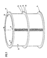
- Figures 1 and 2 show that the screen basket from three support rings 10, 12 and 14 as well as several profile bars 16 exists, the latter parallel to a sieve axis 18 run and the support rings in perpendicular to the sieve axis Levels.
- profile bars 16 so in the screen basket shown formed and arranged that the inlet side 20 for the Sorting fiber suspension on the inner circumference of the screen basket lies, the outlet side 22 for those let through the screen basket Fiber suspension on its outer circumference.
- everyone's particular identically designed support rings 10, 12 and 14 has one Cross section in the form of a flat rectangle and has one upper flat side 24, a lower flat side 26, an outer edge 28 and an inner edge 30.
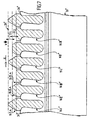
- Fig. 3 shows a short section of a still straight Profile bar support 10 ', which later by bending to the closed support ring 10 is to be reshaped.
- the one Inner edge 30 of the support ring 10 corresponding first edge of the Profile bar support 10 ' was designated 30', the Outer edge 28 of the support ring 10 corresponding second edge of the Profile bar support 10 'with 28', and the visible in Fig. 3 upper flat side of the profile bar support was designated with 24 '.
- the profile bar support 10 ' a cutout 34, in which a profile rod 16 in the direction the longitudinal extension of the profile bar can be inserted. All cutouts 34 should have the same shape and the same dimensions have, and the same applies to the profile bars 16.
- the cross section of a profile bar is approximately mushroom-shaped a mushroom head forming a first cross-sectional end region 16A and a second cross-sectional end portion 16B forming roughly club-shaped mushroom foot, the shape of the second cross-sectional end portion 16B of the shape of the cutout 34 corresponds to, one sees proportionately low, in Fig. 3 recognizable play of the profile bar 16 in Section 34 from.
- the shape of the cutout 34 is now designed so that the cutout 34 is a constriction 34A has between the and the second edge 28 'of End of cutout 34 facing profile bar support 10 ' the latter forms an undercut 34B in the area thereof the edge of the cutout 34 has an approximately straight flank 34C has, with a designated in Fig. 3 at 40, perpendicular to the drawing level of FIG. 3 level forms an acute angle ⁇ , which is towards the second Edge 28 'of the profile bar support 10' opens.
- the closed support ring 10 plane 40 is a diameter plane of the strainer basket.
- the second cross-sectional end region 16B of the profiled bars 16 forms a protrusion 16C that fits into the undercut 34B of the associated cutout 34 engages so that before the deformation of the profile bar support 10 'according to the invention the profile rod 16 not according to FIG. 3 upwards from the cutout 34 can be pulled out.
- FIG. 3 leaves, the outer periphery of each profile bar 16th in the area of the second cross-sectional end area 16B of the profile bar even before the profile rod carrier is deformed according to the invention 10 'everywhere at least almost free of play against Edge of the assigned section 34 with the exception of one relatively narrow gap between the flank 34C of the Section 34 and the projection 16C of the profile bar.
- This Gap is caused by the deformation of the profile bar support according to the invention 10 'closed in the following way:
- a lower pressure roller 62 is pressed at the bottom (see FIG. 6), which around each other and to the flat sides of the profile bar support 10 'or the support ring 10 parallel axes 60' or 62 'are freely rotatable (the axes 60', 62 'also run perpendicular to the longitudinal direction of the section bar support 10 'or radial to the sieve axis 18).
- the pressure rollers 60 and 62 are under control or regulation of the pressure with which they according 6 in the vertical direction against the profile bar support 10 ' or the support ring 10 are pressed on all profile bars 16 passed along the profile bar support 10 'or around the Support ring 10 guided around and thus produce with their in Fig. 6th recognizable displacement ribs 60A and 62A on the upper and on the lower flat side of the profile bar support 10 'or Tragrings 10 (of course, the same applies accordingly to the Support ring 12 and the support ring 14) in the immediate vicinity the profile bars 16 each have a groove 70A and 70B and as a result of the design according to the invention which can be seen in FIG.
- FIG. 4 represents a section of FIG. 2 and do not show the profile bar support 10 ', but already the upper support ring 10, you can see that the profile bars 16 even after the profiled bars have been formed into closed ones
- Support rings between slot-shaped sieve openings Form 80, which run parallel to the sieve axis 18 and between the support rings 10, 12 and 12, 14 are open, respectively.
- the inlet side 20 communicates via the sieve openings 80 the outlet side 22 of the screen basket.
- the profile bars are in the first cross-sectional end regions 16A 16 on the sieve inlet side 20 with inclined flanks 82 and 84 and provided with rear flanks 86 and 88.
- the inclined flanks 82 and 84 form that which can be seen in FIG. 3
- Level 40 acute angles that are the same size or different and the rear flanks 86 and 88 lie in particular before carrying out the invention Deformation against the first edge 30 'of the profile bar support 10 'on.
- the inlet side is known 20 of the screen basket adjacent to a rotor in the to be sorted
- the first cross-sectional areas create fiber suspension 16A of the profile bars 16 in particular with their inclined Flanks 82 and 84 in the fiber suspension to be sorted Microturbulence, which is the formation of a significant Nonwoven fabric on the sieve inlet side 20 and a blockage counteract the screen openings 80.
- the second embodiment shown in Figures 7 to 9 differs from the first embodiment Figures 1 to 6 only in the design of the sieve outlet side turned away first long sides of the profile bars, namely in the design of the first cross-sectional areas of the profile bars with which the latter over those The edges of the support rings protrude from which the sieve inlet side are facing. Therefore, in Figures 7 to 9, as far possible, the same reference numerals are used as in the figures 1 to 6, but with the addition of two dashes.
- FIG. 7 is intended to be the illustration in FIG. 4 correspond, but with the modification that Fig. 7 none still shows straight beam, but the processing an annular support ring, which is consequently shown in Fig. 7 was shown as a straight element.
- a support ring 10 "holds a series of profile bars 16I", 16II “and 16III", which with their first cross-sectional end areas 16IA, 16IIA and 16IIIA protrude beyond the edge 30 "of the support ring 10" facing the sieve inlet side 20 "(see FIG 7).
- the Profile bars 16I “, 16II” and 16III “differ from each other essentially only in that the cross-sectional areas 16IA, 16IIA and 16IIIA formed series of profile bar sections against each other in the longitudinal direction of the bar are offset.
- the screen has several identical in the circumferential direction successive Profile bar groups, each of which groups is formed of three profile bars, namely a profile bar 16I ", one Profile bar 16II "and a profile bar 16III", which in the Sequence the order listed above.
- the arrow R was drawn, which should indicate the direction in which the to be sorted Fiber suspension flows along the inlet side 20 "of the sieve, in the case of a sorter with a rotor, the arrow R indicates but also the direction of rotation of the rotor, in particular that Direction, in the last or so-called cleaning wing of the rotor on the inlet side 20 "of the sieve.
- the first cross-sectional areas always in the order 16IIIA, 16IIA and 16IA on top of each other.
- the first cross-sectional end regions 16IA, 16IIA and 16IIIA protrude to different degrees into the fiber suspension to be sorted, ie they protrude differently beyond the inner edges 30 "of the support rings.
- the differences in the protrusions were shown in FIG D 1 and D 2 denote, where D 1 and D 2 can be of different sizes or of the same size - values of D 1 and D 2 of approximately the same size are preferred, particularly in the case of screen baskets for so-called pressure sorters, D 1 and D 2 are at most 1 mm, preferably 0.5 to 0.8 mm and in particular approximately 0.5 to approximately 0.6 mm.
- L 1 or L 2 or L 3 are the same size, which is to mean that the cross sections of the cross-sectional end regions 16IA, 16IIA and 1 6IIIA should not change over their axial length, which obviously does not necessarily have to be the case.
- L 1 or L 2 or L 3 is preferably approximately 15% to approximately 30% of the axial length of the sieve, in particular equal to 1/5 to 1/4 of the sieve length.
- L 1 or L 2 or L 3 is in a range from 150 to 200 mm.
- the different high or differently projecting cross-sectional end areas or profile bar sections 16IA, 16IIA and 16IIIA according to the invention arranged according to a special pattern such that one in Fig. 8 in the direction of arrow R on the sieve inlet side flowing, sorting fiber suspension a axial flow component or an enlarged axial flow component in the direction of the sieve axis, d. H. according to Fig.
Landscapes
- Chemical & Material Sciences (AREA)
- Chemical Kinetics & Catalysis (AREA)
- Engineering & Computer Science (AREA)
- Mechanical Engineering (AREA)
- Manufacturing & Machinery (AREA)
- Paper (AREA)
- Inorganic Fibers (AREA)
- Artificial Filaments (AREA)
- Nonwoven Fabrics (AREA)
Abstract
Description
Die Erfindung betrifft ein Sieb für Fasersuspensionen mit einer bezüglich einer Siebachse im wesentlichen rotationssymmetrischen Form, dessen eine, erste Umfangsseite eine Einlaßseite und dessen anderen, zweite Umfangsseite eine Auslaßseite des Siebs für die Fasersuspension bildet, sowie mit einer Serie von Profilstäben, die sich quer zur Siebumfangsrichtung erstrecken, in Siebumfangsrichtung in gleichen Abständen voneinander angeordnet sind und zwischen sich schlitzförmige Sieböffnungen bilden, und mit wenigstens zwei in senkrecht zur Siebachse verlaufenden Ebenen liegenden und in Richtung der Siebachse im Abstand voneinander angeordneten Tragringen, von denen jeder in seinem der Siebeinlaßseite zugewandten ersten Randbereich eine Serie von der Siebeinlaßseite zu randoffenen Ausschnitten besitzt, in die die Profilstäbe eingesetzt sind, und zwar so, daß sie mit einem Teil ihres Querschnitts in radialer Richtung über die ersten Ränder der Tragringe überstehen.The invention relates to a sieve for fiber suspensions one essentially rotationally symmetrical with respect to a sieve axis Form, the one, first peripheral side an inlet side and its other, second peripheral side is an outlet side of the sieve for the fiber suspension, as well as with a series of profile bars that are transverse to the direction of the wire circumference extend in the circumferential direction at equal intervals are arranged from each other and between themselves form slit-shaped sieve openings, and with at least two in planes perpendicular to the sieve axis and spaced from each other in the direction of the sieve axis Tragrings, each in its sieve inlet side facing first edge area a series from the sieve inlet side to open-cut-outs in which the profile bars are used, and so that they with a part their cross-section in the radial direction over the first Project over the edges of the support rings.
Derartige sogenannte Stabsiebkörbe sind insbesondere bekannt aus der EP-B-0 417 408 und der dieser entsprechenden DE-A-39 27 748, der EP-A-0 499 154 und der dieser entsprechenden DE-A-41 04 615 sowie aus der EP-A-0 705 936.Such so-called strainer baskets are known in particular from EP-B-0 417 408 and the corresponding one DE-A-39 27 748, EP-A-0 499 154 and the corresponding ones DE-A-41 04 615 and from EP-A-0 705 936.
Diese Veröffentlichungen beschreiben verschiedene Methoden zur Festlegung der Profilstäbe in den Ausschnitten der Tragringe, wobei bei allen diesen Stabsiebkörben deren Innenumfang die Einlaßseite für die zu sortierende Fasersuspension bildet. These publications describe different methods to determine the profile bars in the cutouts of the Support rings, with all of these rod screen baskets the inner circumference the inlet side for the fiber suspension to be sorted forms.
Zur Herstellung des Stabsiebkorbs nach der EP-B-0 417 408 werden die randoffenen Ausschnitte in zunächst geraden oder nur leicht gebogenen Profilstabträgern erzeugt, welche später zu geschlossenen Tragringen gebogen werden. Die randoffenen Ausschnitte haben eine solche Form, daß sie in radialem Abstand vom ersten Rand der Profilstabträger, in den die Ausschnitte münden, jeweils eine Hinterschneidung bilden, und die Querschnittsform der Profilstäbe ist an die Gestalt der Ausschnitte so angepaßt, daß ein Vorsprung des Profilstabquerschnitts in diese Hinterschneidung eingreift und so die Profilstäbe formschlüssig in den Ausschnitten gehalten werden und quer zur Längsrichtung der Profilstabträger nicht aus den Ausschnitten herausgleiten können. Wenn dann die Profilstabträger zu geschlossenen Tragringen gebogen werden, hat die dabei erzeugte Verengung der Ausschnitte zur Folge, daß die Profilstäbe in den Ausschnitten der Tragringe eingespannt sind. Sowohl die Profilstabträger, als auch die schließlich aus diesen erzeugten Tragringe dieses bekannten Stabsiebkorbs haben eine einem flachen Rechteck entsprechende Querschnittsform.For the production of the screen basket according to EP-B-0 417 408 the cut-outs are initially straight or only slightly curved profile beam supports, which later be bent into closed support rings. The edge open Cutouts have such a shape that they are at a radial distance from the first edge of the profile beam into which the cutouts flow, each form an undercut, and the cross-sectional shape of the profile bars is based on the shape of the Cutouts adjusted so that a projection of the profile bar cross-section engages in this undercut and so the Profile bars are held in a form-fitting manner in the cutouts and not transversely to the longitudinal direction of the profiled bar supports Can slide out cutouts. If so, the profile beam have to be bent into closed support rings narrowing of the cutouts resulted in the fact that the Profile bars clamped in the cutouts of the support rings are. Both the profile bar supports, and finally from this produced support rings of this known strainer basket have a cross-sectional shape corresponding to a flat rectangle.
Von diesem bekannten Stabsiebkorb unterscheidet sich der Stabsiebkorb nach der EP-A-0 499 154 bzw. der DE-A-41 04 615 nur dadurch, daß es die Gestaltung der Hinterschneidungen der Ausschnitte der Profilstabträger und der in diese Hinterschneidungen eingreifenden Vorsprünge der Profilstäbe erlaubt, die Profilstäbe quer zu ihrer Längsrichtung in die randoffenen Ausschnitte der Profilstabträger einzuführen, wobei sich eine Art Schnappverschluß ergibt, durch den die Profilstäbe daran gehindert werden, quer zu ihrer Längsrichtung wieder aus den Ausschnitten der Profilstabträger herauszugleiten. Während also bei der Herstellung des Stabsiebkorbs nach der EP-B-0 417 408 die Profilstäbe in ihrer Längsrichtung in die Ausschnitte der Profilstabträger eingeschoben werden, erfolgt bei der Herstellung des Stabsiebkorbs nach der EP-A-0 499 154 das Einführen der Profilstäbe in die Ausschnitte der Profilstabträger quer zur Längsrichtung der Profilstäbe. Sodann werden auch bei der Herstellung des Stabsiebkorbs nach der EP-A-0 499 154 die Profilstabträger zu geschlossenen Tragringen gebogen und dadurch die Profilstäbe in den Ausschnitten eingespannt.The differs from this known strainer basket Bar screen basket according to EP-A-0 499 154 and DE-A-41 04 615 only in that it is the design of the undercuts of the Cut-outs of the profile bar supports and those in these undercuts engaging projections of the profile bars allowed, the profile bars transverse to their longitudinal direction in the insert open-edge cutouts of the profile beam, resulting in a kind of snap, through which the Profile bars are prevented from running transversely to their longitudinal direction slide out of the cut-outs of the profile beam. So while in the production of the strainer basket according to EP-B-0 417 408 the profile bars in their longitudinal direction inserted into the cutouts of the profile bar supports are carried out during the manufacture of the screen basket EP-A-0 499 154 introduces the profile bars into the cutouts the profile bar carrier transverse to the longitudinal direction of the profile bars. Then also in the manufacture of the screen basket according to EP-A-0 499 154, the profile rod supports closed support rings bent and thereby the profile bars clamped in the cutouts.
Bei dem Stabsiebkorb nach der EP-A-0 705 936 haben die Profilstäbe einen T-förmigen Querschnitt und die randoffenen Ausschnitte der Tragringe die Form eines rechteckigen Schlitzes, in den in radialer Richtung von innen her die den Fuß des T-förmigen Querschnitts bildende Rippe eines Profilstabs eingeschoben wird. Sodann werden um die Tragringe Spannringe herumgelegt, welche die Tragringe im Sinne einer Durchmesserverkleinerung in radialer Richtung zusammenpressen, wodurch die besagten Rippen der Profiistäbe in den Tragringausschnitten eingespannt werden sollen.In the bar screen basket according to EP-A-0 705 936 they have Profile bars have a T-shaped cross-section and the open edges Cutouts of the support rings in the form of a rectangular slot, in the radial direction from the inside of the foot of the T-shaped cross-section forming rib of a profile bar is inserted. Then there are tension rings around the support rings put around, which the support rings in the sense of a diameter reduction compress in the radial direction, whereby the said ribs of the professional rods in the support ring cutouts to be clamped.
In sogenannten Sortierern für Fasersuspensionen zur Herstellung von Papier, Karton und dergleichen werden nun Siebkörbe recht unterschiedlichen Durchmessers eingesetzt, wobei man jedoch aus Kostengründen bestrebt ist, stets Profilstäbe mit identischen Querschnittsformen und Querschnittsabmessungen zu verwenden. Bei den Stabsiebkörben nach der EP-B-0 417 408 und der EP-A-0 499 154 hängt nun aber die Größe der Einspannkräfte, durch die die Profilstäbe in den Tragringen festgehalten werden, ganz wesentlich vom Durchmesser der Tragringe ab, in die die Profilstabträger nach dem Einsetzen der Profilstäbe in die randoffenen Ausschnitte der Profilstabträger umgeformt werden, es sei denn, man würde die Gestalt bzw. Abmessungen der in den Profilstabträgern zu erzeugenden Ausschnitte in Abhängigkeit vom Durchmesser des herzustellenden Stabsiebkorbs variieren, eine Maßnahme, welche naturgemäß zu einer Erhöhung der Herstellkosten führt - mit unabhängig vom Siebkorbdurchmesser gestalteten Ausschnitten ergeben sich Einspannkräfte, die mit zunehmendem Siebkorbdurchmesser immer geringer werden. Bei der Herstellung der sich aus der EP-B-0 417 408 und der EP-A-0 499 154 bekannt gewordenen Stabsiebkörbe können sich außerdem die Profilstäbe in Stablängsrichtung gegenüber den Profilstabträgern noch verschieben, was sich während des Biegens der Profilstabträger zu geschlossenen Tragringen als hinderlich erweisen kann - erst durch diesen Biegevorgang werden ja die Profilstäbe in den Ausschnitten eingespannt, und natürlich müssen bei einem fertigen Stabsiebkorb die einen bzw. anderen Enden aller Profilstäbe in derselben, senkrecht zur Siebachse verlaufenden Ebene liegen.In so-called sorters for fiber suspensions for production of paper, cardboard and the like are now sieve baskets quite different diameter used, where one but strives for cost reasons, always with profile bars identical cross-sectional shapes and cross-sectional dimensions use. For the strainer baskets according to EP-B-0 417 408 and EP-A-0 499 154 now depends on the size of the clamping forces, through which the profile bars are held in the support rings are very much the diameter of the support rings into which the profile bar supports after inserting the profile bars into the open cutouts of the profile bar supports be reshaped unless you would change the shape or dimensions of the cutouts to be created in the profile beam depending on the diameter of the manufactured Strainer basket vary, a measure that naturally goes too leads to an increase in manufacturing costs - regardless of Sieve basket-shaped cutouts result Clamping forces that always increase with the sieve basket diameter decrease. In the manufacture of the EP-B-0 417 408 and EP-A-0 499 154 Bar strainers can also be the profile bars in the longitudinal direction shift compared to the beam members, what happens during the bending of the profile beam closed support rings can prove a hindrance - only through this bending process, the profile bars are in the Clippings clamped in, and of course have to finish one Bar screen basket one or the other ends of all profile bars in the same, perpendicular to the sieve axis Level.
Die sich aus der EP-A-0 705 936 ergebende Festlegung der Profilstäbe in den Tragringen dürfte nicht nur deshalb problematisch sein, weil das Anbringen und Schließen der die Tragringe in radialer Richtung nach innen pressenden Spannringe problematisch erscheint, wenn hinreichend große Einspannkräfte erzeugt werden sollen, sondern dieser bekannte Stabsiebkorb erfordert eben auch noch zusätzlich das Herstellen und Anbringen der Spannringe.The stipulation resulting from EP-A-0 705 936 Profile bars in the support rings should not be the only reason be problematic because attaching and closing the the Support rings in the radial direction pressing clamping rings appears problematic when sufficiently large clamping forces should be generated, but this known Bar screen basket also requires additional manufacturing and attaching the clamping rings.
Der Erfindung lag nun die Aufgabe zugrunde, einen Stabsiebkorb und ein Verfahren zu seiner Herstellung zu schaffen, der bzw. das es nicht nur ermöglicht, verhältnismäßig einfach die Profilstäbe dauerhaft präzise an den Tragringen festzulegen, sondern auch die Möglichkeit eröffnet, Siebkörbe recht unterschiedlichen Durchmessers unter Verwendung von Profilstäben ein und desselben Querschnitts sowie von Profilstabträgern mit ein und derselben Ausschnittsform herzustellen.The invention was based on the object, a bar screen basket and to create a process for its manufacture which or that it not only makes it relatively easy Fix profile bars permanently precisely to the support rings, but also opens up the possibility of screen baskets being quite different Diameter using profile bars one and the same cross-section as well as from beam members to produce with the same cutout shape.
Zur Lösung dieser Aufgabe wird ausgegangen von einem Sieb für Fasersuspensionen mit einer bezüglich einer Siebachse im wesentlichen rotationssymmetrischen Form, dessen eine, erste Umfangsseite eine Einlaßseite und dessen andere, zweite Umfangsseite eine Auslaßseite des Siebs für die Fasersuspension bildet, mit einer Serie von Profilstäben, welche sich quer zur Siebumfangsrichtung erstrecken, in Siebumfangsrichtung in gleichen Abständen voneinander angeordnet sind sowie zwischen sich schlitzförmige Sieböffnungen bilden und deren Querschnitte jeweils eine längliche Form mit einem ersten, von der Siebauslaßseite abgekehrten Endbereich und einem zweiten, von der Siebeinlaßseite abgekehrten Endbereich besitzen, sowie mit wenigstens zwei in senkrecht zur Siebachse verlaufenden Ebenen liegenden und in Richtung der Siebachse im Abstand voneinander angeordneten Tragringen aus plastisch verformbarem Material, von denen jeder in seinem der Siebeinlaßseite zugewandten ersten Randbereich eine Serie von der Siebeinlaßseite zu randoffenen Ausschnitten besitzt, deren Form - in Richtung der Siebachse gesehen - der Gestalt der in den Ausschnitten liegenden zweiten Querschnittendbereiche der Profilstäbe entspricht und in radialem Abstand von dem der Siebeinlaßseite zugekehrten, ersten Rand des Tragrings eine Hinterschneidung bildet, in welche ein Vorsprung des Profilstabquerschnitts eingreift, so daß die Profilstäbe mit ihren zweiten Querschnittendbereichen in bezüglich der Siebachse radialer Richtung sowie in Siebumfangsrichtung formschlüssig in den Tragringausschnitten gehalten sind, wobei die Profilstäbe in radialer Richtung über die ersten Ränder der Tragringe überstehen und infolge einer plastischen Verformung der Tragringe mit ihren zweiten Querschnittendbereichen in den Tragringausschnitten eingespannt sind.To solve this task, a sieve for Fiber suspensions with one with respect to a sieve axis in the essential rotationally symmetrical shape, one, the first The peripheral side is an inlet side and its other, second peripheral side an outlet side of the screen for the fiber suspension forms, with a series of profile bars that cross extend to the wire circumferential direction, in the wire circumferential direction in are equally spaced from each other and between form slit-shaped sieve openings and their cross sections each an elongated shape with a first, of the end area facing away from the sieve outlet and a second, end area facing away from the sieve inlet side, and with at least two in perpendicular to the sieve axis Layers lying in the direction of the sieve axis at a distance support rings arranged from one another made of plastically deformable Material, each in its sieve inlet side facing first edge area a series of the Has sieve inlet side to open cutouts, whose Form - viewed in the direction of the sieve axis - the shape of the in the cut-out second cross-sectional areas of Corresponds to profile bars and at a radial distance from that of Sieve inlet side facing, first edge of the support ring one Undercut forms in which a projection of the Profile cross section engages so that the profile bars with their second cross-sectional areas in relation to the sieve axis radial direction and in the circumferential direction of the screen are held in the support ring cutouts, wherein the profile bars in the radial direction over the first edges of the support rings protrude and as a result of plastic deformation the support rings with their second cross-sectional areas are clamped in the support ring cutouts.
Erfindungsgemäß wird ein solches Sieb nun so gestaltet, daß die Tragringe auf der der Siebauslaßseite zugewandten Seite der Profilstäbe derart plastisch verformte Bereiche aufweisen, daß infolge einer Verdrängung von Tragringmaterial in Richtung auf die Siebeinlaßseite die Profilstabvorsprünge in dieser Richtung gegen die Hinterschneidungen angepreßt werden.According to the invention, such a sieve is now designed in such a way that the support rings on the side facing the sieve outlet side the profiled bars have such plastically deformed areas, that due to a displacement of support ring material in Towards the sieve inlet side the profile rod protrusions in be pressed against the undercuts in this direction.
Bei der Herstellung eines erfindungsgemäßen Siebkorbs wird also auf der der Siebauslaßseite zugewandten Seite eines jeden Profilstabs Tragringmaterial in Richtung auf den benachbarten Profilstab verdrängt, und zwar so, daß dadurch dieser Profilstab durch das verdrängte Tragringmaterial und/oder durch eine Verlagerung des der Siebauslaßseite zugewandten Randbereichs des diesen Profilstab haltenden Ausschnitts relativ zum Tragring in Richtung auf die Siebeinlaßseite etwas verlagert und dadurch mit seinem Vorsprung in dieser Richtung gegen die vom Tragringausschnitt gebildete Hinterschneidung angepreßt und so auch in radialer Richtung des Siebkorbs dauerhaft präzise fixiert wird. Gleichzeitig werden die zuvor in ihrer Längsrichtung in die Ausschnitte eingeschobenen Profilstäbe auch in Stablängsrichtung fixiert.In the manufacture of a screen basket according to the invention that is, on the side of the sieve outlet side facing one each support rod material in the direction of the neighboring Profile bar displaced, in such a way that this profile bar through the displaced support ring material and / or by shifting the one facing the sieve outlet side Edge area of the cutout holding this profile bar relative to the support ring in the direction of the sieve inlet side somewhat shifted and thus with its lead in this direction against that formed by the support ring cutout Undercut pressed and so in the radial direction of the strainer basket is permanently fixed precisely. simultaneously be the cutouts in their longitudinal direction inserted profile bars also fixed in the longitudinal direction.
Da die erfindungsgemäße Art der Befestigung der Profilstäbe an den Tragringen bzw. den Profilstabträgern keine bestimmte Gestaltung der über die Tragringe in bezüglich der Siebachse radialer Richtung nach innen bzw. nach außen überstehenden Bereiche der Profilstäbe voraussetzt, können diese Bereiche erfindungsgemäß auch in einer neuartigen und besonders vorteilhaften Weise gestaltet werden: Since the type of attachment of the profile bars according to the invention no particular on the support rings or the profile bar supports Design of the support rings in relation to the sieve axis protruding radially inwards or outwards Areas of the profile bars presuppose these areas according to the invention also in a novel and particularly advantageous Ways to be designed:
Bei den bekannten sogenannten Stabsiebkörben sind - betrachtet man einen bestimmten Siebkorb - alle Profilstäbe gleich ausgebildet, und jeder Profilstab besitzt über seine ganze Länge denselben Querschnitt. Im Gegensatz zu dieser bekannten Gestaltung der Profilstäbe wird nun erfindungsgemäß vorgeschlagen, in Siebumfangsrichtung hintereinander angeordnete Profilstäbe an ihren von der Siebauslaßseite abgekehrten ersten Längsseiten derart unterschiedlich auszubilden, daß die Profilstäbe einer an der Siebeinlaßseite in Siebumfangsrichtung strömenden Fasersuspension eine in Richtung der Siebachse gerichtete axiale Strömungskomponente verleihen oder eine solche axiale Strömungskomponente vergrößern. Hierzu könnten die Profilstäbe an ihren genannten ersten Längsseiten z. B. mit Nuten oder Rippen versehen werden, welche mit der Siebumfangsrichtung einen spitzen Winkel bilden und so an der Einlaßseite des Stabsiebkorbs für die dort umlaufende, zu sortierende Fasersuspension schräg gestellte Leit- bzw. Umlenkflächen bilden.In the known so-called screen strainers are considered a certain sieve basket - all profile bars are the same trained, and each profile bar has its whole Length same cross section. In contrast to this known Design of the profile bars is now proposed according to the invention, arranged one behind the other in the circumferential direction of the sieve Profile bars on their facing away from the sieve outlet side to form the first long sides so differently that the profile bars on the sieve inlet side in the circumferential direction of the sieve flowing fiber suspension one towards the Give axis axial directional flow component or enlarge such an axial flow component. For this purpose, the profile bars could be at their first mentioned Long sides z. B. be provided with grooves or ribs, which form an acute angle with the circumferential direction of the sieve and so on the inlet side of the strainer basket for those there all-round fiber suspension to be sorted inclined Form baffles.
Wenn vorstehend von in Siebumfangsrichtung hintereinander angeordneten Profilstäben die Rede ist, so darf dies nicht derart einengend interpretiert werden, als ob alle Profilstäbe oder in Siebumfangsrichtung unmittelbar aufeinanderfolgende Profilstäbe an ihren ersten Längsseiten erfindungsgemäß gestaltet sein müßten, obwohl derartige Ausführungsformen bevorzugt werden. Die Profilstäbe müssen an ihren ersten Längsseiten auch nicht über die ganze Profilstablänge erfindungsgemäß gestaltet sein, da es unter Umständen ausreicht, nur in einem axialen Abschnitt des Siebs Mittel vorzusehen, welche eine axiale Strömungskomponente entstehen lassen oder eine solche Strömungskomponente vergrößern - der damit erzielbare Vorteil wird später noch erläutert werden. If above arranged one behind the other in the circumferential direction of the sieve Profile bars is mentioned, it must not be so be interpreted restrictively as if all profile bars or immediately consecutive in the circumferential direction of the sieve Profile bars designed according to the invention on their first long sides should be, although such embodiments are preferred become. The profile bars must be on their first long sides also not over the entire profile bar length according to the invention be designed, as it may be sufficient only in an axial portion of the screen to provide means which create an axial flow component or one enlarge such flow component - the achievable Advantage will be explained later.
Erfindungsgemäß einzusetzende Profilstäbe lassen sich dann verhältnismäßig einfach herstellen, wenn die Profilstäbe an ihren ersten Längsseiten abschnittsweise unterschiedlich weit über die ersten Tragringränder überstehen; derart gestaltete Profilstäbe lassen sich z. B. aus stranggepreßten Profilstäben mit überall gleichem Querschnitt durch eine abschnittsweise erfolgende zerspanende Bearbeitung, wie Fräsen, herstellen. Sind dann am Stabsiebkorb die unterschiedlich weit über die Tragringe überstehenden Profilstababschnitte nach Art eines schraubenlinienförmigen Musters angeordnet, verleihen sie einer an der Siebeinlaßseite in Siebumfangsrichtung strömenden Fasersuspension nicht nur eine in Richtung der Siebachse gerichtete axiale Strömungskomponente oder führen zur Vergrößerung einer solchen axialen Strömungskomponente, sondern die über die Tragringe unterschiedlich weit überstehenden Profilstababschnitte bewirken auch noch eine Auflockerung des sogenannten Spuckstoffs, wodurch das Beschädigungsrisiko von Stabsiebkörbe enthaltenden Sortierern herabgesetzt wird: Bei Sortierern für Fasersuspensionen bildet der Innenumfang des Stabsiebkorbs meist dessen Einlaßseite und innerhalb des Siebkorbs rotiert um dessen Achse ein Rotor, der mit Leisten versehen ist, welche in geringem Abstand von der Einlaßseite des Siebs an dieser vorbeilaufen, sich entweder parallel zur Siebachse erstrecken oder mit deren Richtung einen kleinen spitzen Winkel bilden und dazu dienen, an der Einlaßseite des Siebs in der zu sortierenden Fasersuspension positive und negative Druckstöße zu erzeugen. Fasern, Faserzusammenballungen und in der zu sortierenden Fasersuspension enthaltene Verunreinigungen, welche die Sieböffnungen des Siebkorbs nicht passieren (d. h. der sogenannte Spuckstoff), haben nun die Tendenz, sich an den in Umlaufrichtung vorn liegenden Flanken der Rotorleisten anzusammeln, und solche Spuckstoffzusammenballungen können zu einem Bruch des Siebkorbs führen, wenn sie sich zwischen einer umlaufenden Rotorleiste und dem Siebkorb "verketten". Bei sogenannten Drucksortierern, in die die zu sortierende Fasersuspension unter Druck einströmt und in denen der Siebkorb an seinem einen axialen Ende mit der zu sortierenden Fasersuspension beaufschlagt wird, während derjenige Teil der zu sortierenden Fasersuspension, welcher die Sieböffnungen nicht passiert, den Siebkorb an dessen anderem axialen Ende verläßt, hat die unter dem Einfluß des Rotors an der Einlaßseite des Siebkorbs im wesentlichen in Siebumfängsrichtung entlangströmende Fasersuspension stets auch eine in Richtung der Siebachse gerichtete axiale Strömungskomponente, und zwar aufgrund des vorstehend beschriebenen Anströmens des Siebkorbs mit der zu sortierenden Fasersuspension sowie der Tatsache, daß der Spuckstoff den Siebkorb an seinem anderen Ende verläßt; infolgedessen wandern die vorstehend beschriebenen Spuckstoffansammlungen an den Rotorleisten entlang und verstärken sich immer mehr, es sei denn, der Rotor wird nicht mit über seine ganze axiale Länge durchgehenden Leisten versehen, sondern - wie an sich bekannt - mit Leistenabschnitten, zwischen denen sich Lücken befinden und die oft auch in Rotorumfangsrichtung gegeneinander versetzt sind. Ähnlich wie diese Lücken zwischen den Leistenabschnitten eines Rotors führen nun auch die erfindungsgemäß angeordneten, über die ersten Tragringränder überstehenden Profilstababschnitte zu einer Auflockerung von Spuckstoffzusammenballungen und vermindern so das Beschädigungsrisiko für den Stabsiebkorb.Profile bars to be used according to the invention can then be used relatively easy to manufacture when the profile bars their first long sides differ in sections protrude beyond the first support ring edges; so designed Profile bars can be z. B. from extruded profile bars with the same cross-section everywhere through a section machining, such as milling, produce. Are then different on the strainer basket Profile bar sections protruding far beyond the support rings arranged in the manner of a helical pattern, they give one on the sieve inlet side in the circumferential direction of the sieve flowing fiber suspension not just one in the direction the sieve axis directed axial flow component or lead to the enlargement of such an axial flow component, but the distance over the support rings protruding profile bar sections also cause a Loosening of the so-called rejects, which reduces the risk of damage of screen baskets containing sorters is reduced: In sorters for fiber suspensions the inner circumference of the strainer basket usually its inlet side and rotates within the strainer basket around its axis Rotor, which is provided with strips, which in low Distance from the inlet side of the sieve, extend either parallel to the sieve axis or with whose direction form a small acute angle and to it serve on the inlet side of the sieve in the to be sorted Fiber suspension to generate positive and negative pressure surges. Fibers, fiber aggregations and in the to be sorted Fiber suspension contains contaminants, which the sieve openings of the strainer basket (i.e. the so-called Rejects), now have a tendency to adhere to the direction of rotation accumulate the flanks of the rotor strips at the front, and such agglomerations of rejects can cause the screen basket to break lead if they are between a rotating rotor bar and the "Link" strainer basket. In so-called pressure sorters, in which the to be sorted Fiber suspension flows in under pressure and in which the screen basket its one axial end with the fiber suspension to be sorted while that part of the fiber suspension to be sorted, which does not pass through the sieve openings, the sieve basket at its other leaves axial end, which has under the influence of the rotor on the inlet side of the strainer essentially flowing in the circumferential direction of the strainer Fiber suspension always also an axial in the direction of the sieve axis Flow component, due to the above Flow against the sieve basket with the fiber suspension to be sorted and the Fact that the rejects leave the strainer at its other end; as a result, the accumulations of rejects described above migrate along the rotor strips and reinforce more and more, it is because the rotor will not be continuous over its entire axial length Strips, but - as known per se - with strip sections, between which there are gaps and often also in the rotor circumferential direction are offset from each other. Similar to these gaps between the Strip sections of a rotor now also guide the inventive, Profile bar sections protruding beyond the first support ring edges to loosen up accumulations of rejects and thus reduce them the risk of damage to the strainer basket.
Um die an der Siebeinlaßseite vorbeiströmende, zu sortierende Fasersuspension
mit einer axialen Strömungskomponente in Richtung der Siebachse bzw.
mit einer vergrößerten solchen axialen Strömungskomponente zu versehen,
empfiehlt sich die Maßnahme nach Anspruch 20, wobei die Ansprüche 21 bis
28 noch weitere Verbesserungen definieren. Sogenannte Stabsiebkörbe, bei
denen die Profilstäbe an ihren der Siebeinlaßseite zugekehrten Längsseiten
derart ausgebildet sind, daß die Profilstäbe einer an der Siebeinlaßseite in
Siebumfangsrichtung strömenden Fasersuspension eine In Richtung der Siebachse
gerichtete axiale Strömungskomponente verleihen, sind an sich bekannt,
und zwar aus der DE-C-196 25 726 sowie der US-A-5 234 550, wobei
die DE-C-196 25 726 einen Stabsiebkorb zeigt, dessen Profilstäbe an der
Siebeinlaßseite abschnittsweise unterschiedlich weit über die die Profilstäbe
haltenden Tragringe überstehen.Around the fiber suspension to be sorted flowing past the sieve inlet side
with an axial flow component in the direction of the sieve axis or
to be provided with such an enlarged axial flow component,
the measure according to
Die Erfindung betrifft auch ein Verfahren zur Herstellung eines Siebs für Fasersuspensionen mit einer bezüglich einer Siebachse im wesentlichen rotationssymmetrischen Form, dessen eine, erste Umfängsseite eine Einlaßsefte und dessen andere, zweite Umfangsseite eine Auslaßseite des Siebs für die Fasersuspension bildet, mit einer Serie von Profilstäben, welche sich quer zur Siebumfangsrichtung erstrecken, in Siebumfangsrichtung in gleichen Abständen voneinander angeordnet sind sowie zwischen sich schlitzförmige Sieböffnungen bilden und deren Querschnitte jeweils eine längliche Form mit einem ersten, von der Siebauslaßseite abgekehrten Endbereich und einem zweiten, von der Siebeinlaßseite abgekehrten Endbereich besitzen, sowie mit wenigstens zwei in senkrecht zur Siebachse verlaufenden Ebenen liegenden und in Richtung der Siebachse im Abstand voneinander angeordneten ringförmigen Profilstabträgern aus plastisch verformbarem Material, von denen jeder in seinem der Siebeinlaßseite zugewandten ersten Randbereich eine Serie von der Siebeinlaßseite zu randoffenen Ausschnitten besitzt, deren Form - in Richtung der Siebachse gesehen - der Gestalt der in den Ausschnitten liegenden zweiten Querschnittendbereiche der Profilstäbe entspricht und in radialem Abstand von dem der Siebeinlaßseite zugekehrten, ersten Rand des Profilstabträgers eine Hinterschneidung bildet, in welche ein Vorsprung des Profilstabquerschnitts eingreift, so daß die Profilstäbe mit ihren zweiten Querschnittendbereichen in bezüglich der Siebachse radialer Richtung sowie in Siebumfangsrichtung formschlüssig in den Ausschnitten der Profilstabträger gehalten sind sowie mit ihren ersten Querschnittendbereichen in radialer Richtung über die ersten Ränder der Profilstabträger überstehen, wobei die Profilstabträger zunächst mit Ausschnitten versehen werden, welche etwas größer sind als die zweiten Querschnittendbereiche der Profilstabe, worauf die Profilstabe in die Profilstabträgerausschnitte eingesetzt und sodann durch eine plastische Verformung der Profilstabträger in deren Ausschnitten eingespannt werden. The invention also relates to a method for producing a sieve for fiber suspensions with an essentially rotationally symmetrical with respect to a sieve axis Form, one, first circumferential side of an inlet sect and the other, second peripheral side an outlet side of the sieve for the fiber suspension forms, with a series of profile bars, which extend transversely to the wire circumferential direction, in the wire circumferential direction are arranged at equal distances from each other and form slit-shaped sieve openings between them and whose cross sections each have an elongated shape with a first end area facing away from the sieve outlet side and a second end area facing away from the sieve inlet side own, as well as with at least two in perpendicular to the sieve axis running levels and towards the sieve axis spaced apart annular profile bar supports made of plastically deformable material, of which each in its first, facing the sieve inlet side Edge area a series from the sieve inlet side to the edge open Has cutouts whose shape - in the direction of the sieve axis seen - the shape of those lying in the cutouts corresponds to the second cross-sectional areas of the profile bars and at a radial distance from that facing the sieve inlet side, an undercut in the first edge of the profile beam forms in which a projection of the profile bar cross-section engages so that the profile bars with their second Cross-sectional areas in radial with respect to the sieve axis Direction and in the circumferential direction of the screen in the form Cutouts of the profile beam are held as well their first cross-sectional areas in the radial direction protrude beyond the first edges of the profile beam, whereby the profile beam is first provided with cutouts, which are slightly larger than the second cross-sectional areas the profile bar, whereupon the profile bar into the profile bar support cutouts used and then by a plastic deformation of the profile beam in their cutouts be clamped.
Erfindungsgemäß wird ein solches Verfahren so gestaltet, daß die Profilstabträger auf der von ihren ersten Rändern abgewandten Seite der Profilstäbe derart plastisch verformt werden, daß infolge einer Verdrängung von Profilstabträgermaterial in Richtung auf die ersten Profilstabträgerränder die Profilstabvorsprünge in dieser Richtung gegen die Hinterschneidungen angepreßt werden.According to the invention, such a method is designed such that the beam supports on the side facing away from their first edges Side of the profile bars are plastically deformed in such a way that as a result of displacement of profile support material towards the first profile beam support edges the profile rod projections in this direction against the undercuts be pressed.
Wenn dabei vorstehend davon die Rede war, daß die Profilstabträger zunächst mit Ausschnitten versehen werden, die etwas größer sind als die zweiten Querschnittendbereiche der Profilstäbe, so darf diese Aussage nicht so interpretiert werden, daß die Profilstabträgerausschnitte zunächst in jeder Richtung etwas größer sein müssen als die zweiten Querschnittendbereiche der Profilstäbe, da es die erfindungsgemäße Lösung der gestellten Aufgabe nur erforderlich macht, Profilstabträgermaterial in Richtung auf die ersten Profilstabträgerränder zu verdrängen, um die Profilstabvorsprünge in dieser Richtung gegen die von den Profilstabträgerausschnitten gebildeten Hinterschneidungen anzupressen.If it was mentioned above that the profile beam first be provided with cutouts that something are larger than the second cross-sectional areas of the Profile bars, this statement should not be interpreted in this way be that the profile bar cutouts first in each Direction must be slightly larger than the second cross-sectional areas the profile bars, since it is the invention Solving the task only requires Profile beam material in the direction of the first profile beam edges to displace the profile bar protrusions in this direction against that of the profile bar cutouts to press undercuts formed.
Wie sich aus dem Vorstehenden ergibt, kann bei dem erfindungsgemäßen Herstellverfahren von geraden oder nur geringfügig gebogenen Profilstabträgern ausgegangen werden, in deren Ausschnitten die Profilstäbe durch Verdrängung von Profilstabträgermaterial eingespannt werden, worauf die Profilstabträger zu geschlossenen Ringen gebogen werden; ebensogut ist es aber auch möglich, die Profilstabträger mit oder ohne Profilstäbe zu geschlossenen Tragringen umzuformen und erst dann die in die Tragringausschnitte eingesetzten Profilstäbe durch Verdrängung von Profilstabträger- bzw. Tragringmaterial in den Ausschnitten zu fixieren. Fixiert man die Profilstäbe bereits an den noch nicht zu Tragringen umgeformten Profilstabträgern, so ergibt sich gegenüber dem Stand der Technik nach der EP-B-0 417 408 bzw. der EP-A-0 499 154 der Vorteil, daß sich bereits vor dem Biegen der Profilstabträger zu geschlossenen Tragringen ein festes Gitter ergibt, dessen Profilstäbe sich gegenüber den Profilstabträgern nicht mehr verschieben können, und zwar auch nicht während des Umformens der Profilstabträger zu geschlossenen Tragringen.As can be seen from the above, in the case of the invention Manufacturing process of straight or only marginally curved profile beam supports are assumed the cutouts of the profile bars by displacement of Profile bar support material are clamped, whereupon the Profile bar supports are bent into closed rings; but it is also possible to use the profile beam or without forming profile bars into closed support rings and only then those inserted in the support ring cutouts Profile bars by displacement of profile bar support or Fix the support ring material in the cutouts. One fixes the profile bars already on the not yet formed into support rings Profile beam carriers, this results in relation to the stand the technology according to EP-B-0 417 408 and EP-A-0 499 154 the advantage that there is already before the bending of the profile beam results in a solid grid for closed support rings, whose profile bars are not compared to the profile bar supports can move more, not even during the forming process the profile bar support to closed support rings.
Die gemäß der Erfindung zu bewirkende Verdrängung von Profilstabträger- bzw. Tragringmaterial könnte z. B. dadurch erfolgen, daß man den von den Ausschnittöffnungen abgewandten Randbereich eines Profilstabträgers bzw. Tragrings mit zunächst rechteckigem Querschnitt zwischen zwei Druckwalzen bzw. -rollen mit gegeneinander und gegenüber der Ebene des Tragrings bzw. des Profilstabträgers gekippten Achsen so walzverformt, daß die Verformung eine Materialverdrängung in Richtung auf die Profilstäbe bewirkt. Alternativ könnte man in unmittelbarer Nachbarschaft eines jeden Profilstabs an einer oder beiden Seiten des Tragrings bzw. Profilstabträgers in diesem für jeden Profilstab eine diskrete Vertiefung einprägen, z. B. mittels eines Prägestempels. Bevorzugt werden jedoch Ausführungsformen, bei denen die verformten Tragring- bzw. Profilstabträgerbereiche eingepreßte Rinnen aufweisen, welche entlang der ganzen Siebstabserie verlaufen, und zwar insbesondere in unmittelbarer Nachbarschaft der Profilstäbe.The displacement of profile bar supports to be effected according to the invention or support ring material could, for. B. done by that one faces away from the cutout openings Edge area of a profile bar support or support ring with initially rectangular cross section between two pressure rollers or roles with each other and against the level of Support ring or the profile rod carrier tilted axes so Rollformed that the deformation a material displacement in Direction on the profile bars. Alternatively you could in the immediate vicinity of each profile bar one or both sides of the support ring or profile beam emboss a discrete indentation for each profile bar, z. B. by means of an embossing stamp. To be favoured however, embodiments in which the deformed support ring or profile bar support areas have pressed-in channels, which run along the entire series of sieves, namely especially in the immediate vicinity of the profile bars.
Im allgemeinen werden die Tragringe aus einem geeigneten Metall bzw. einer geeigneten Metallegierung bestehen, es ist jedoch grundsätzlich auch möglich, statt dessen ein hinreichend verschleißfestes Kunststoffmaterial zu verwenden, welches sich - gegebenenfalls unter Erwärmen - ausreichend plastisch verformen läßt, jedoch nicht zu einem Kriechen dergestalt neigt, daß dadurch die Einspannkräfte, durch die die Profilstäbe in den Tragringen fixiert werden, im Laufe der Zeit abgebaut werden.In general, the support rings are made from a suitable one Metal or a suitable metal alloy exist, it is however, in principle also possible, instead a sufficient one to use wear-resistant plastic material, which - if necessary with heating - is sufficient plastically deformed, but not to creep so tends that the clamping forces by which the profile bars are fixed in the support rings during the course of time are reduced.
Nachdem die Profilstabträger zu Ringen gebogen wurden, werden die letzteren dadurch geschlossen, daß die Enden der Profilstabträger miteinander verschweißt werden. Dadurch entstehen in den Tragringen Eigenspannungen, welche vor allem bei Sortierern, bei denen mit Hilfe eines Rotors nahe dem Siebkorb in der Fasersuspension positive und negative Druckstöße erzeugt werden, zu Dauerbrüchen in den Tragringen führen können. Zur Vermeidung dieses Risikos wird erfingungsgemäß vorgeschlagen, die geschweißten Tragringe mindestens im Bereich ihrer Schweißverbindungen einer Wärmebehandlung zu unterziehen, um so die durch das Schweißen erzeugten Eigenspannungen zu reduzieren oder ganz zu beseitigen. Erfolgt die Wärmebehandlung vor dem Festlegen der Profilstäbe in den Ausschnitten der Tragringe, ist es auch nicht erforderlich, die Wärmebehandlung eng auf die eigentliche Schweißstelle zu beschränken, um zu verhindern, daß durch die Wärmebehandlung die die Profilstäbe in den Tragringen fixierenden Einspannkräfte reduziert werden.After the profile bar supports have been bent into rings the latter closed by the ends of the profiled bar supports are welded together. This creates internal stresses in the support rings, which are particularly where with the help of a rotor near the screen basket generates positive and negative pressure surges in the fiber suspension can lead to permanent breaks in the support rings. According to the invention, in order to avoid this risk, it is proposed that the welded support rings at least in the area subject their welded joints to heat treatment, especially the residual stresses generated by welding reduce or eliminate entirely. Does that happen Heat treatment before fixing the profile bars in the cutouts of the support rings, it is also not necessary Restrict heat treatment closely to the actual welding point, to prevent heat treatment the clamping forces fixing the profile bars in the support rings be reduced.
Bevorzugt werden metallische Profilstäbe, obwohl grundsätzlich auch Profilstäbe aus einem anderen Material denkbar sind, z. B. aus einem hinreichend harten und gegenüber einer Biegebeanspruchung hinreichend widerstandsfähigen Kunststoff, oder aus einem keramischen Material. Auch wird empfohlen, für die Profilstabe einen Werkstoff zu verwenden, dessen Festigkeit höher ist als die Festigkeit des für die Tragringe bzw. die Profilstabträger verwendeten Werkstoffs, um zu verhindern, daß beim Verformen der Profilstäbe bzw. Tragringe und dem dadurch bewirkten Anpressen der Ränder der Tragring- bzw. Profilstabträgerausschnitte gegen die Profilstäbe in letzteren Kerben entstehen können, die bei der Wechseldruckbeanspruchung des Siebs in einem Sortierer mit an der Siebeinlaßoder der Siebauslaßseite umlaufendem Rotor zu Dauerbrüchen an den Profilstäben führen könnten.Metallic profile bars are preferred, although basically Profile bars made of a different material are also conceivable are, e.g. B. from a sufficiently hard and compared to one Bending stress sufficiently resistant plastic, or from a ceramic material. It is also recommended for the profile bar to use a material whose strength is higher than the strength of the support rings or the profile beam supports used material to prevent that when deforming the profile bars or support rings and the resulting pressing of the edges of the support ring or Profile bar carrier cutouts against the profile bars in the latter Notches can arise in the alternating pressure of the sieve in a sorter with at the sieve inlet or of the rotating outlet rotor to permanent breaks the profile bars could lead.
Weitere Merkmale besonders bevorzugter Ausführungsformen des erfindungsgemäßen Siebs bzw. des erfindungsgemäßen Herstellungsverfahrens ergeben sich aus den beigefügten Ansprüchen und/oder aus der nachfolgenden Beschreibung sowie der beigefügten zeichnerischen Darstellung zweier besonders vorteilhafter Ausführungsformen des erfindungsgemäßen Siebs und seiner Herstellung; in der Zeichnung zeigen:
- Fig. 1
- eine perspektivische und weitgehend schematisierte Darstellung der ersten Ausführungsform des erfindungsgemäßen Stabsiebkorbs, welche nur einige wenige Profilstäbe erkennen läßt;
- Fig. 2
- eine Draufsicht auf den in Fig. 1 dargestellten Stabsiebkorb, wobei wiederum nur einige wenige Profilstäbe gezeichnet wurden;
- Fig. 3
- eine Draufsicht auf einen verhältnismäßig kurzen Abschnitt eines noch gestreckten bzw. geraden Profilstabträgers mit drei im Querschnitt gezeichneten Profilstäben, welche bereits in Ausschnitte des Profilstabträgers eingeschoben wurden, jedoch an letzterem noch nicht fixiert sind, d. h. also vor der erfindungsgemäßen plastischen Verformung des Profilstabträgers;
- Fig. 4
- eine der Fig. 3 entsprechende Darstellung, jedoch nach der erfindungsgemäßen plastischen Verformung des Profilstabträgers zwecks Verdrängung von Profilstabträgermaterial in Richtung auf die Profilstäbe;
- Fig. 5
- einen Schnitt nach der Linie 5-5 in Fig. 4;
- Fig. 6
- eine der Fig. 5 entsprechende Darstellung, jedoch samt zwei Walzwerkzeugen zur erfindungsgemäßen plastischen Verformung des Profilstabträgers;
- Fig. 7
- eine der Fig. 4 entsprechende Darstellung der zweiten Ausführungsform;
- Fig. 8
- einen Teil einer Abwicklung der zweiten Ausführungsform des erfindungsgemäßen Stabsiebkorbs, und zwar einer Ansicht seiner Einlaßseite gesehen in Richtung des Pfeils X aus Fig. 7, und
- Fig. 9
- eine Seitenansicht des über die Tragringe überstehenden Bereichs eines Profilstabs der zweiten Ausführungsform, gesehen in Richtung des Pfeils R aus Fig. 7, wobei jedoch nur ein Teil der Länge dieses Profilstabs dargestellt wurde.
- Fig. 1
- a perspective and largely schematic representation of the first embodiment of the screen basket according to the invention, which shows only a few profile bars;
- Fig. 2
- a plan view of the bar screen basket shown in Figure 1, again only a few profile bars have been drawn.
- Fig. 3
- a plan view of a relatively short section of a still elongated or straight profile bar support with three profile bars drawn in cross section, which have already been inserted into sections of the profile bar support, but are not yet fixed to the latter, that is to say before the plastic deformation of the profile bar support according to the invention;
- Fig. 4
- a representation corresponding to FIG 3, but after the plastic deformation of the profile bar support according to the invention for the purpose of displacing profile bar support material in the direction of the profile bars;
- Fig. 5
- a section along the line 5-5 in Fig. 4;
- Fig. 6
- an illustration corresponding to FIG. 5, but including two rolling tools for the plastic deformation of the profiled bar support according to the invention;
- Fig. 7
- one of the 4 corresponding representation of the second embodiment;
- Fig. 8
- a part of a development of the second embodiment of the screen basket according to the invention, namely a view of its inlet side seen in the direction of arrow X from Fig. 7, and
- Fig. 9
- a side view of the projecting beyond the support rings of a section bar of the second embodiment, viewed in the direction of arrow R from Fig. 7, but only a part of the length of this section bar has been shown.
Ergänzend sei vorab bemerkt, daß die Fig. 5 auch einen Schnitt entsprechend der Linie 5-5 in Fig. 2 darstellen könnte und die Fig. 6 infolgedessen die auf den bereits geschlossenen Tragring einwirkenden Walzwerkzeuge. In addition, it should be noted in advance that Fig. 5 also one Represent section along the line 5-5 in Fig. 2 6 and, as a result, could be based on the already closed supporting ring acting rolling tools.
Die Figuren 1 und 2 lassen erkennen, daß der Stabsiebkorb aus
drei Tragringen 10, 12 und 14 sowie aus mehreren Profilstäben
16 besteht, wobei letztere parallel zu einer Siebachse 18
verlaufen und die Tragringe in zur Siebachse senkrechten
Ebenen liegen. Wie sich aus dem Folgenden noch ergeben wird,
sind bei dem dargestellten Siebkorb die Profilstäbe 16 so
ausgebildet und angeordnet, daß die Einlaßseite 20 für die zu
sortierende Fasersuspension am Innenumfang des Siebkorbs
liegt, die Auslaßseite 22 für die vom Siebkorb durchgelassene
Fasersuspension an dessen Außenumfang. Jeder der insbesondere
identisch ausgebildeten Tragringe 10, 12 und 14 hat einen
Querschnitt in Form eines flachen Rechtecks und besitzt eine
obere Flachseite 24, eine untere Flachseite 26, einen Außenrand
28 und einen Innenrand 30.Figures 1 and 2 show that the screen basket from
three support rings 10, 12 and 14 as well as several profile bars
16 exists, the latter parallel to a
Die Fig. 3 zeigt einen kurzen Abschnitt eines noch geraden
Profilstabträgers 10', welcher später durch Biegen zu dem
geschlossenen Tragring 10 umgeformt werden soll. Der dem
Innenrand 30 des Tragrings 10 entsprechende erste Rand des
Profilstabträgers 10' wurde mit 30' bezeichnet, der dem
Außenrand 28 des Tragrings 10 entsprechende zweite Rand des
Profilstabträgers 10' mit 28', und die in Fig. 3 sichtbare
obere Flachseite des Profilstabträgers wurde mit 24' bezeichnet.
Für jeden Profilstab 16 hat der Profilstabträger 10'
einen Ausschnitt 34, in den sich ein Profilstab 16 in Richtung
der Längserstreckung des Profilstabs einschieben läßt.
Alle Ausschnitte 34 sollen dieselbe Gestalt und dieselben Abmessungen
haben, und gleiches gilt für die Profilstäbe 16.
Der Querschnitt eines Profilstabs ist ungefähr pilzförmig mit
einem einen ersten Querschnittendbereich 16A bildenden Pilzkopf
und einem einen zweiten Querschnittendbereich 16B bildenden,
ungefähr keulenförmigen Pilzfuß, wobei die Gestalt
des zweiten Querschnittendbereichs 16B der Gestalt des Ausschnitts
34 entspricht, sieht man von einem verhältnismäßig
geringen, in Fig. 3 erkennbaren Spiel des Profilstabs 16 im
Ausschnitt 34 ab.Fig. 3 shows a short section of a still straight
Profile bar support 10 ', which later by bending to the
Die Form des Ausschnitts 34, dessen Flanken senkrecht zur
oberen bzw. unteren Flachseite des Profilstabträgers 10' verlaufen,
ist nun so gestaltet, daß der Ausschnitt 34 eine Engstelle
34A hat, zwischen der und dem dem zweiten Rand 28' des
Profilstabträgers 10' zugewandten Ende des Ausschnitts 34
letzterer eine Hinterschneidung 34B bildet, in deren Bereich
der Rand des Ausschnitts 34 eine ungefähr gerade Flanke 34C
besitzt, die mit einer in Fig. 3 mit 40 bezeichneten, senkrecht
zur Zeichnungsebene der Fig. 3 verlaufenden Ebene einen
spitzen Winkel α bildet, der sich in Richtung auf den zweiten
Rand 28' des Profilstabträgers 10' öffnet. Nach dem Umformen
des Profilstabträgers 10' zum geschlossenen Tragring 10 bildet
die Ebene 40 eine Durchmesserebene des Stabsiebkorbs.The shape of the
Der zweite Querschnittendbereich 16B der Profilstäbe 16 bildet
einen Vorsprung 16C, der in die Hinterschneidung 34B des
zugeordneten Ausschnitts 34 eingreift, so daß sich schon vor
der erfindungsgemäßen Verformung des Profilstabträgers 10'
der Profilstab 16 nicht gemäß Fig. 3 nach oben aus dem Ausschnitt
34 herausziehen läßt. Wie die Fig. 3 gleichfalls erkennen
läßt, liegt der Außenumfang eines jeden Profilstabs 16
im Bereich des zweiten Querschnittendbereichs 16B des Profilstabs
schon vor der erfindungsgemäßen Verformung des Profilstabträgers
10' überall zumindest nahezu spielfrei gegen den
Rand des zugeordneten Ausschnitts 34 an mit Ausnahme eines
verhältnismäßig schmalen Spalts zwischen der Flanke 34C des
Ausschnitts 34 und dem Vorsprung 16C des Profilstabs. Dieser
Spalt wird durch die erfindungsgemäße Verformung des Profilstabträgers
10' in folgender Weise geschlossen:The second
Gegen den Profilstabträger 10' (gegebenenfalls gegen den
Tragring 10) wird von oben eine obere Druckrolle 60 und von
unten eine untere Druckrolle 62 angepreßt (siehe Fig. 6),
welche um zueinander und zu den Flachseiten des Profilstabträgers
10' bzw. des Tragrings 10 parallele Achsen 60' bzw.
62' frei drehbar sind (die Achsen 60', 62' verlaufen außerdem
senkrecht zur Längsrichtung des Profilstabträgers 10' bzw.
radial zur Siebachse 18). Die Druckrolle 60 und 62 werden
unter Steuerung bzw. Regelung des Drucks, mit dem sie gemäß
Fig. 6 in vertikaler Richtung gegen den Profilstabträger 10'
bzw. den Tragring 10 angepreßt werden, an allen Profilstäben
16 vorbei dem Profilstabträger 10' entlanggeführt bzw. um den
Tragring 10 herumgeführt und erzeugen so mit ihren in Fig. 6
erkennbaren Verdrängungsrippen 60A bzw. 62A an der oberen und
an der unteren Flachseite des Profilstabträgers 10' bzw. des
Tragrings 10 (gleiches gilt natürlich entsprechend für den
Tragring 12 und den Tragring 14) in unmittelbarer Nachbarschaft
der Profilstäbe 16 jeweils eine Rinne 70A bzw. 70B und
infolge der in Fig. 6 erkennbaren erfindungsgemäßen Gestaltung
des Profils der Verdrängungsrippe 60A bzw. 62A einen
gegen die Profilstäbe 16 aufgeworfenen Wulst 72A bzw. 72B, so
daß durch diese Materialverdrängung die Profilstäbe 16 geringfügig
gemäß Fig. 3 nach oben verlagert werden
(einschließlich des gemäß Fig. 3 unteren Randbereichs eines
jeden der Ausschnitte 34) und auf diese Weise, wie in Fig. 4
erkennbar, der zuvor vorhandene Spalt zwischen der Flanke 34C
der Ausschnitte 34 und dem Vorsprung 16C der Profilstäbe 16
geschlossen wird mit der Folge, daß die Profilstabe in den
Ausschnitten eingespannt sind. Der in Fig. 3 erkennbare Winkel
α wird dabei zweckmäßigerweise so bemessen, daß nach der
erfindungsgemäßen Verformung zwischen der Flanke 34C und der
dagegen angepreßten Flanke des Vorsprungs 16C Selbsthemmung
gegeben ist.Against the profile bar support 10 '(possibly against the
Support ring 10) is an
Nimmt man nun an, die Fig. 4 stelle einen Ausschnitt aus Fig.
2 dar und zeige nicht den Profilstabträger 10', sondern bereits
den oberen Tragring 10, erkennt man, daß die Profilstäbe
16 auch nach Umformung der Profilstabträger in geschlossene
Tragringe zwischen sich schlitzförmige Sieböffnungen
80 bilden, welche parallel zur Siebachse 18 verlaufen und
zwischen den Tragringen 10, 12 bzw. 12, 14 offen sind, d. h.
über die Sieböffnungen 80 kommuniziert die Einlaßseite 20 mit
der Auslaßseite 22 des Siebkorbs.Assuming now that FIG. 4 represents a section of FIG.
2 and do not show the profile bar support 10 ', but already
the
In den ersten Querschnittendbereichen 16A sind die Profilstäbe
16 an der Siebeinlaßseite 20 mit geneigten Flanken 82
und 84 sowie mit hinteren Flanken 86 und 88 versehen. Die
geneigten Flanken 82 und 84 bilden mit der in Fig. 3 erkennbaren
Ebene 40 spitze Winkel, die gleich groß oder unterschiedlich
sein können, und die hinteren Flanken 86 und 88
liegen insbesondere vor Durchführung der erfindungsgemäßen
Verformung gegen den ersten Rand 30' des Profilstabträgers
10' an.The profile bars are in the first cross-sectional
Bei Sortierern, bei denen in bekannter Weise der Einlaßseite
20 des Siebkorbs benachbart ein Rotor in der zu sortierenden
Fasersuspension umläuft, erzeugen die ersten Querschnittendbereiche
16A der Profilstäbe 16 insbesondere mit ihren geneigten
Flanken 82 und 84 in der zu sortierenden Fasersuspension
Mikroturbulenzen, welche der Ausbildung eines nennenswerten
Faservlieses an der Siebeinlaßseite 20 und einer Verstopfung
der Sieböffnungen 80 entgegenwirken. For sorters where the inlet side is known
20 of the screen basket adjacent to a rotor in the to be sorted
The first cross-sectional areas create fiber suspension
16A of the profile bars 16 in particular with their
Da in modernen Sortierern für die Aufbereitung von Fasersuspensionen feinste Sieböffnungen gefordert werden und mit hohen Stoffdichten (hoher Faseranteil der aufzubereitenden Fasersuspensionen) gearbeitet wird, ist es auch notwendig, mit dem oben erwähnten Rotor des Sortierers in der Fasersuspension hohe Druck- und Sogimpulse zu erzeugen, um einem Verstopfen der Sieböffnungen entgegenzuwirken. Diese hohen Druck- und Sogimpulse führen dazu, daß entsprechend hohe Kräfte auf die Profilstäbe einwirken, so daß diese unbedingt dauerhaft einen festen Halt in den Tragringen haben müssen. Diese Forderung läßt sich auf einfache Weise mit der vorliegenden Erfindung erfüllen, da durch die erfindungsgemäße Materialverdrängung die Profilstäbe fest in den Ausschnitten der Tragringe eingespannt werden, und zwar auch bei großen Siebkorbdurchmessern und infolgedessen entsprechend kleinen Biegungen beim Umformen der Profilstabträger in die Tragringe.Because in modern sorters for the preparation of fiber suspensions finest sieve openings are required and with high consistency (high fiber content of the reprocessed Fiber suspensions) is worked, it is also necessary with the sorter rotor mentioned above in the fiber suspension to generate high pressure and suction impulses to one Counteract clogging of the sieve openings. These high Pressure and suction impulses lead to correspondingly high Forces act on the profile bars, so that these are essential permanently have to have a firm hold in the support rings. This requirement can be easily met with the present one Fulfill invention, as by the invention Material displacement the profile bars firmly in the cutouts the support rings can be clamped, even with large ones Strainer basket diameters and consequently correspondingly small Bends when reshaping the profile beam into Support rings.
Die in den Figuren 7 bis 9 dargestellte zweite Ausführungsform unterscheidet sich von der ersten Ausführungsform nach den Figuren 1 bis 6 nur in der Gestaltung der von der Siebauslaßseite abgekehrten ersten Längsseiten der Profilstäbe, und zwar in der Gestaltung der ersten Querschnittendbereiche der Profilstäbe, mit denen die letzteren über diejenigen Ränder der Tragringe überstehen, welche der Siebeinlaßseite zugewandt sind. Deshalb wurden in den Figuren 7 bis 9, soweit möglich, dieselben Bezugszeichen verwendet wie in den Figuren 1 bis 6, jedoch unter Hinzufügung zweier Striche.The second embodiment shown in Figures 7 to 9 differs from the first embodiment Figures 1 to 6 only in the design of the sieve outlet side turned away first long sides of the profile bars, namely in the design of the first cross-sectional areas of the profile bars with which the latter over those The edges of the support rings protrude from which the sieve inlet side are facing. Therefore, in Figures 7 to 9, as far possible, the same reference numerals are used as in the figures 1 to 6, but with the addition of two dashes.
Die Darstellung in Fig. 7 soll zwar der Darstellung in Fig. 4 entsprechen, jedoch mit der Abwandlung, daß die Fig. 7 keinen noch geraden Profilstabträger zeigt, sondern die Abwicklung eines kreisringförmigen Tragrings, der infolgedessen in Fig. 7 als gerades Element dargestellt wurde.The illustration in FIG. 7 is intended to be the illustration in FIG. 4 correspond, but with the modification that Fig. 7 none still shows straight beam, but the processing an annular support ring, which is consequently shown in Fig. 7 was shown as a straight element.
Bei der zweiten Ausführungsform hält ein Tragring 10" eine
Serie von Profilstäben 16I", 16II" und 16III", welche mit
ihren ersten Querschnittendbereichen 16IA, 16IIA und 16IIIA
über den der Siebeinlaßseite 20" zugewandten Rand 30" des
Tragrings 10" überstehen (siehe Fig. 7).In the second embodiment, a
Wie sich aus den Figuren 8 und 9 ergibt, hat jeder der
Profilstabe 16I", 16II" und 16III" eine sich in Stablängsrichtung
periodisch wiederholende Serie von in Stablängsrichtung
aufeinanderfolgenden Querschnittendbereichen 16IA, 16IIA
und 16IIIA und damit eine sich in Stablängsrichtung periodisch
wiederholende Serie von in Stablängsrichtung aufeinanderfolgenden
Abschnitten unterschiedlichen Überstands. Die
Profilstäbe 16I", 16II" und 16III" unterscheiden sich voneinander
also im wesentlichen nur dadurch, daß die von den Querschnittendbereichen
16IA, 16IIA und 16IIIA gebildeten Serien
von Profilstababschnitten in Stablängsrichtung gegeneinander
versetzt sind.As can be seen from FIGS. 8 and 9, each of the
Ferner hat bei der zweiten Ausführungsform das Sieb mehrere
in Siebumfangsrichtung aufeinanderfolgende, identische
Profilstabgruppen, wobei jede dieser Gruppen gebildet wird
von drei Profilstäben, nämlich einem Profilstab 16I", einem
Profilstab 16II" und einem Profilstab 16III", welche in der
vorstehend aufgeführten Reihenfolge aufeinanderfolgen.Furthermore, in the second embodiment, the screen has several
identical in the circumferential direction successive
Profile bar groups, each of which groups is formed
of three profile bars, namely a
In die Figuren 7 und 8 wurde der Pfeil R eingezeichnet, welcher
diejenige Richtung angeben soll, in der die zu sortierende
Fasersuspension an der Einlaßseite 20" des Siebs entlangströmt,
bei einem Sortierer mit Rotor gibt der Pfeil R
aber auch die Rotordrehrichtung an, insbesondere also diejenige
Richtung, in der Leisten oder sogenannte Reinigungsflügel
des Rotors an der Einlaßseite 20" des Siebs vorbeilaufen.
Bei der dargestellten Ausführungsform folgen in einem
axialen Siebabschnitt in Richtung R die ersten Querschnittendbereiche
also stets in der Reihenfolge 16IIIA, 16IIA und
16IA aufeinander.In the figures 7 and 8, the arrow R was drawn, which
should indicate the direction in which the to be sorted
Fiber suspension flows along the
Wie in Fig. 7 dargestellt, ragen die ersten Querschnittendbereiche
16IA, 16IIA und 16IIIA unterschiedlich weit in die
zu sortierende Fasersuspension hinein, d. h. sie stehen
unterschiedlich weit über die Innenränder 30" der Tragringe
vor. Die Unterschiede in den überständen wurden in Fig. 7 mit
D1 und D2 bezeichnet, wobei D1 und D2 unterschiedlich groß
oder gleich groß sein können - ungefähr gleich große Werte
von D1 und D2 werden dabei bevorzugt. Insbesondere bei Siebkörben
für sogenannte Drucksortierer sind D1 und D2 höchstens
gleich 1 mm, vorzugsweise 0,5 bis 0,8 mm und insbesondere ca.
0,5 bis ca. 0,6 mm. In Fig. 8 wurden die in Richtung der
Siebachse bzw. in Profilstablängsrichtung gemessenen Längen
der Querschnittendbereiche 16IA, 16IIA und 16IIIA mit L1 bzw.
L2 bzw. L3 bezeichnet; bei der dargestellten, bevorzugten
Ausführungsform sind L1, L2 und L3 gleich groß, was bedeuten
soll, daß sich die Querschnitte der Querschnittendbereiche
16IA, 16IIA und 16IIIA über deren axiale Länge nicht ändern
sollen, was jedoch ersichtlich nicht unbedingt der Fall sein
muß. Bei einem Sieb mit ungefähr kreiszylindrischer Gestalt
ist L1 bzw. L2 bzw. L3 vorzugsweise ungefähr 15 % bis ungefähr
30 % der axialen Länge des Siebs, insbesondere gleich 1/5 bis
1/4 der Sieblänge. Bei einer axialen Sieblänge von beispielsweise
800 mm liegt L1 bzw. L2 bzw. L3 also in einem Bereich
von 150 bis 200 mm. As shown in FIG. 7, the first cross-sectional end regions 16IA, 16IIA and 16IIIA protrude to different degrees into the fiber suspension to be sorted, ie they protrude differently beyond the
Wie die Fig. 8 erkennen läßt, sind auf der Einlaßseite 20"
des erfindungsgemäßen Siebs die unterschiedlich hohen bzw.
unterschiedlich weit vorspringenden Querschnittsendbereiche
bzw. Profilstababschnitte 16IA, 16IIA und 16IIIA erfindungsgemäß
nach einem besonderen Muster angeordnet dergestalt, daß
eine in Fig. 8 in Richtung des Pfeils R an der Siebeinlaßseite
vorbeiströmende, zu sortierende Fasersuspension eine
axiale Strömungskomponente bzw. eine vergrößerte axiale Strömungskomponente
in Richtung der Siebachse erhält, d. h. gemäß
Fig. 8 nach unten abgelenkt wird, da einer Reihe von in Richtung
R aufeinanderfolgender Profilstababschnitte 16IIIA,
16IIA und 16IA, deren Überstand in Richtung R zunimmt, in dem
sich nach unten anschließenden axialen Siebabschnitt eine
Reihe ebensolcher Profilstababschnitte benachbart ist, welche
jedoch gegenüber der erstgenannten Reihe entgegen der Richtung
R versetzt ist, und zwar und das Maß der sogenannten Teilung
des Siebs, d. h. um den in Richtung R gemessenen Abstand
der Längsmittelebenen zweier einander benachbarter Profilstäbe.
Ein solcher Versatz wird bevorzugt, obwohl grundsätzlich
auch ein doppelt so großer Versatz möglich wäre.As can be seen in FIG. 8, on the
Claims (37)
- Screen for fibre suspensions having a shape which is essentially rotationally symmetrical in relation to a screen axis (18), a first circumferential side of said screen forming an inlet side (20) and the other, second circumferential side thereof forming an outlet side (22) of said screen for the fibre suspension, with a series of profiled bars (16) extending transversely to the circumferential direction of the screen, said profiled bars being arranged at equal spacings from one another in the circumferential direction of the screen and forming slot-shaped screen openings (80) between them, the cross sections of said profiled bars each having an elongate shape with a first end region facing away from the screen outlet side and a second end region facing away from the screen inlet side, and with at least two supporting rings (10, 12, 14) made of plastically deformable material, said supporting rings lying in planes extending perpendicularly to said screen axis and being arranged in spaced relation to one another in the direction of said screen axis, each of said supporting rings having in its first edge region facing said screen inlet side a series of cut-outs open at their edge towards said screen inlet side, the shape of said cut-outs - viewed in the direction of said screen axis - corresponding to the configuration of the second cross-sectional end regions of said profiled bars lying in said cut-outs, and forming at a radial spacing from the first edge of said supporting ring facing said screen inlet side an undercut (34B) in which a projection of said profiled bar cross section engages so that said profiled bars are held positively in a radial direction in relation to said screen axis and in the circumferential direction of said screen with their second cross-sectional end regions in said supporting ring cut-outs, said profiled bars projecting in a radial direction over the first edges (30) of said supporting rings, and being clamped with their second cross-sectional end regions in said supporting ring cut-outs as a result of a plastic deformation of said supporting rings, characterized in that said supporting rings (10, 12, 14) have on the side of said profiled bars (16) facing said screen outlet side (22) such deformed regions (70A, 70B, 72A, 72B) that as a result of a displacement of supporting ring material in the direction towards said screen inlet side (20) said profiled bar projections (16C) are pressed in this direction against said undercuts (34B).
- Screen as defined in claim 1, characterized in that said deformed supporting ring regions (70A, 70B, 72A, 72B) comprise pressed-in recesses (70A, 70B).
- Screen as defined in claim 2, characterized in that said recesses are in the form of ring-shaped grooves (70A, 70B) extending around said screen axis.
- Screen as defined in claim 2 or 3, characterized in that said recesses (70A, 70B) lie on the sides (24, 26) of said supporting rings (10, 12, 14) facing the axial ends of said screen.
- Screen as defined in any one or several of the preceding claims, characterized in that said supporting rings (10, 12, 14) are provided with deformed regions (70A, 70B, 72A, 72B) on both of their sides (24, 26) facing said axial screen ends.
- Screen as defined in claim 5, characterized in that - in the direction of said screen axis (18) - said deformed regions (70A, 72A and 70B, 72B, respectively) of a supporting ring (10, 12, 14) lie opposite each other.
- Screen as defined in any one or several of claims 3 to 6, characterized in that said grooves (70A, 70B) are rolled regions.
- Screen as defined in any one or several of the preceding claims, characterized by metallic profiled bars (16).
- Screen as defined in any one or several of the preceding claims, characterized in that said screen is cylindrical.
- Screen as defined in any one or several of the preceding claims, characterized in that the inner circumferential side of said screen forms the inlet side (20) thereof.
- Screen as defined in any one or several of the preceding claims, characterized in that all profiled bars (16) have the same cross-sectional shape and all supporting ring cut-outs (34) the same configuration.
- Screen as defined in any one or several of the preceding claims, characterized in that the first cross-sectional end regions (16A) of said profiled bars (16) are of such configuration that they generate microturbulences in a fibre suspension rotating at said screen inlet side (20).
- Screen as defined in claim 12, characterized in that the first cross-sectional end regions (16A) of said profiled bars (16) have flanks (82, 84) inclined in relation to a diameter plane (40) of said screen, said flanks forming the legs of an at least approximate isosceles triangle whose angle bisector lies at least approximately in said diameter plane (40).
- Screen as defined in any one or several of the preceding claims, characterized in that - viewed in the direction of said screen axis (18) - said undercut (34B) of said supporting ring cut-outs (34) forms a flank (34C) on that side of the supporting ring cut-out constriction (34A) formed by said undercut (34B) which faces said screen outlet side (22), said flank (34C) being inclined in relation to a diameter plane (40) of said screen running through this constriction at such an acute angle (α) opening towards said screen outlet side (22) that self-locking occurs between this flank (34C) and a flank of said profiled bar projection (16C) pressed against said flank (34C).
- Screen as defined in any one or several of the preceding claims, characterized in that the second end region (16B) of the profiled bar cross section is of approximately club-shaped configuration.
- Screen as defined in any one or several of the preceding claims, characterized In that the first end region (16A) of the profiled bar cross section is of approximately mushroom-head-shaped configuration with flanks (86,88) facing said screen outlet side (22) and forming cooperating stops with the first edge (30) of the pertinent supporting ring (10, 12, 14).
- Screen as defined in any one or several of the preceding claims, characterized in that said supporting rings (10, 12, 14) consist of a material which is different from that of said profiled bars (16).
- Screen as defined in claim 17, characterized in that the material of said profiled bars (16) has a different stability than that of the material of said supporting rings.
- Screen as defined in claim 18, characterized in that the stability of said profiled bar material is greater than the stability of said supporting ring material.
- Screen as defined in any one of claims 1 to 19, characterized in that profiled bars (16I", 16II", 16III") arranged behind one another in the circumferential direction (R) of the screen are of such different configuration at their first longitudinal sides facing away from said screen outlet side that said profiled bars impart an axial flow component oriented in the direction of said screen axis to a fibre suspension flowing at said screen inlet side (20") in the circumferential direction of the screen.
- Screen as defined in claim 20, characterized in that profiled bars (16I", 16II", 16III") arranged so as to follow one another immediately in the circumferential direction (R) of the screen are of such different configuration at their first longitudinal sides at least in one axial section of said screen that said profiled bars impart an axial flow component oriented in the direction of said screen axis to a fibre suspension flowing at said screen inlet side (20") in the circumferential direction of the screen.
- Screen as defined in claim 20 or 21, characterized in that several identical groups of profiled bars (16I", 16II", 16III") follow one another in the circumferential direction (R) of the screen, and the profiled bars of a group differ from one another with respect to the configuration of their first longitudinal sides.
- Screen as defined in any one or several of claims 20 to 22, characterized in that said profiled bars (16I", 16II", 16III") project at their first longitudinal sides section-wise to a varying extent over the first supporting ring edges (30").
- Screen as defined in claim 23, characterized in that each profiled bar (16I", 16II", 16III") has in the longitudinal direction of the bar a periodically repeated series of sections (16IA, 16IIIA, 16IIA) of varying projection following one another in the longitudinal direction of the bar.
- Screen as defined in claim 24, characterized in that the series of profiled bar sections (16IA, 16IIIA, 16IIA) contains the same number of profiled bar sections on each profiled bar, and the projections of profiled bar sections of the same kind are identical.
- Screen as defined in claim 25, characterized in that the length of all profiled bar sections (16IA, 16IIIA, 16IIA) measured in the longitudinal direction of the bar is identical.
- Screen as defined in claims 25 and 26, characterized in that in axial screen sections whose axial length is the same as that of the profiled bar sections (16IA, 16IIIA, 16IIA), different profiled bar sections follow one another in the circumferential direction (R) of the screen.
- Screen as defined in claim 27, characterized in that in each axial screen section, the profiled bar sections (16IA, 16IIIA, 16IIA) are offset in the circumferential direction (R) of the screen in relation to identical profiled bar sections of adjacent axial screen sections such that the profiled bar sections impart an axial flow component oriented in the direction of the screen axis to a fibre suspension flowing at the inlet side (20") of the screen in the circumferential direction of the screen.
- Method for the manufacture of a screen for fibre suspensions having a shape which is essentially rotationally symmetrical in relation to a screen axis, a first circumferential side of said screen forming an inlet side and the other, second circumferential side thereof forming an outlet side of said screen for the fibre suspension, with a series of profiled bars extending transversely to the circumferential direction of the screen, said profiled bars being arranged at equal spacings from one another in the circumferential direction of the screen and forming slot-shaped screen openings between them, the cross sections of said profiled bars each having an elongate shape with a first end region facing away from the screen outlet side and a second end region facing away from the screen inlet side, and with at least two ring-shaped profiled bar supports made of plastically deformable material, said profiled bar supports lying in planes extending perpendicularly to said screen axis and being arranged in spaced relation to one another in the direction of said screen axis, each of said profiled bar supports having in its first edge region facing said screen inlet side a series of cut-outs open at their edge towards said screen inlet side, the shape of said cut-outs - viewed in the direction of said screen axis - corresponding to the configuration of the second cross-sectional end regions of said profiled bars lying in said cut-outs, and forming at a radial spacing from the first edge of said profiled bar support facing said screen inlet side an undercut in which a projection of the profiled bar cross section engages so that said profiled bars are held positively in a radial direction in relation to said screen axis and in the circumferential direction of the screen with their second cross-sectional end regions in said cut-outs of said profiled bar supports and project with their first cross-sectional end regions in a radial direction over the first edges of said profiled bar supports, wherein said profiled bar supports are first provided with cut-outs which are somewhat larger than the second cross-sectional end regions of said profiled bars and said profiled bars are then inserted into said profiled bar support cut-outs and clamped by a plastic deformation of said profiled bar supports in their cut-outs, characterized in that said profiled bar supports are made to undergo plastic deformation on that side of said profiled bars which faces away from the first edges of said profiled bar supports such that as a result of a displacement of profiled bar support material in the direction towards the first profiled bar support edges, the profiled bar projections are pressed in this direction against the undercuts.
- Method as defined in claim 29, characterized in that said profiled bar supports are only bent into closed rings after said profiled bars have been inserted in said profiled bar support cut-outs.
- Method as defined in claim 29 or 30, characterized in that the plastic deformation of said profiled bar supports causing the displacement of material is carried out on the ring-shaped profiled bar supports.
- Method as defined in any one or several of claims 29 to 31, characterized in that the plastic deformation is carried out using a pressure tool.
- Method as defined in claim 32, characterized in that for the plastic deformation of a profiled bar support which brings about the displacement of material, said profiled bar support is clamped between a pressure roll and an abutment, and said pressure roll together with said abutment and said profiled bar support are moved relative to one another in the longitudinal direction of said profiled bar support such that said pressure roll passes all profiled bars of the series of profiled bars.
- Method as defined in claim 33, characterized in that a pressure roll is also used as abutment.
- Method as defined in claim 33 or 34, characterized in that a pressure roll with a rib-shaped circumferential profile is used.
- Method as defined in any one or several of claims 29 to 35, characterized in that a groove extending along the entire series of profiled bars is produced by the plastic deformation in a surface of said profiled bar support extending transversely to the longitudinal direction of said profiled bars.
- Method as defined in claim 36, characterized in that said groove is produced so close to said profiled bars that thus displaced support material forms a bead abutting against said profiled bars.
Applications Claiming Priority (3)
| Application Number | Priority Date | Filing Date | Title |
|---|---|---|---|
| DE19725737A DE19725737A1 (en) | 1997-06-18 | 1997-06-18 | Bar screen basket for fiber suspensions and process for its manufacture |
| DE19725737 | 1997-06-18 | ||
| PCT/EP1998/003574 WO1998057723A1 (en) | 1997-06-18 | 1998-06-13 | Bar screen basket for fiber suspensions and method for the production thereof |
Publications (2)
| Publication Number | Publication Date |
|---|---|
| EP0989897A1 EP0989897A1 (en) | 2000-04-05 |
| EP0989897B1 true EP0989897B1 (en) | 2003-03-26 |
Family
ID=7832831
Family Applications (1)
| Application Number | Title | Priority Date | Filing Date |
|---|---|---|---|
| EP98934957A Expired - Lifetime EP0989897B1 (en) | 1997-06-18 | 1998-06-13 | Bar screen basket for fiber suspensions and method for the production thereof |
Country Status (5)
| Country | Link |
|---|---|
| EP (1) | EP0989897B1 (en) |
| AT (1) | ATE235293T1 (en) |
| CA (1) | CA2293515C (en) |
| DE (2) | DE19725737A1 (en) |
| WO (1) | WO1998057723A1 (en) |
Families Citing this family (4)
| Publication number | Priority date | Publication date | Assignee | Title |
|---|---|---|---|---|
| EP1297218B1 (en) | 2000-02-19 | 2004-11-03 | Voith Paper Patent GmbH | Sieve for fibre suspensions and a method for producing same |
| IT1315545B1 (en) * | 2000-11-13 | 2003-02-18 | Comer Spa | METHOD FOR THE MANUFACTURE OF FILTER BASKETS FOR MACHINES DIFILTRATION OF FIBERS IN Aqueous SUSPENSION AND FILTER BASKET |
| DE102017127562A1 (en) * | 2017-11-22 | 2019-05-23 | Voith Patent Gmbh | screen |
| DE102018101666B3 (en) * | 2018-01-25 | 2018-09-20 | Voith Patent Gmbh | screen cylinder |
Family Cites Families (5)
| Publication number | Priority date | Publication date | Assignee | Title |
|---|---|---|---|---|
| DE3927748C2 (en) * | 1989-08-23 | 1994-03-10 | Voith Gmbh J M | Process for producing a screen basket and screen basket produced according to this method |
| SE466706B (en) * | 1990-07-20 | 1992-03-23 | Kamyr Ab | THE WALL GUARANTEES SEPARATION OF WETAFRAIN FROM A SCIENTIFIC PARTICLE MATERIAL |
| DE4104615A1 (en) * | 1991-02-15 | 1992-08-20 | Voith Gmbh J M | SIEVE BASKET |
| US5394600A (en) * | 1994-02-14 | 1995-03-07 | Chen; Chao-Ho | Method for making a screen |
| DE19625726C1 (en) * | 1996-06-27 | 1997-06-12 | Voith Sulzer Stoffaufbereitung | Wire unit has sorting gaps for fibre suspension |
-
1997
- 1997-06-18 DE DE19725737A patent/DE19725737A1/en not_active Withdrawn
-
1998
- 1998-06-13 EP EP98934957A patent/EP0989897B1/en not_active Expired - Lifetime
- 1998-06-13 WO PCT/EP1998/003574 patent/WO1998057723A1/en active IP Right Grant
- 1998-06-13 CA CA002293515A patent/CA2293515C/en not_active Expired - Fee Related
- 1998-06-13 AT AT98934957T patent/ATE235293T1/en not_active IP Right Cessation
- 1998-06-13 DE DE59807654T patent/DE59807654D1/en not_active Expired - Lifetime
Also Published As
| Publication number | Publication date |
|---|---|
| ATE235293T1 (en) | 2003-04-15 |
| CA2293515C (en) | 2004-06-22 |
| CA2293515A1 (en) | 1998-12-23 |
| WO1998057723A1 (en) | 1998-12-23 |
| EP0989897A1 (en) | 2000-04-05 |
| DE59807654D1 (en) | 2003-04-30 |
| DE19725737A1 (en) | 1998-12-24 |
Similar Documents
| Publication | Publication Date | Title |
|---|---|---|
| EP1297218B1 (en) | Sieve for fibre suspensions and a method for producing same | |
| DE69608109T2 (en) | SCREEN AND PRODUCTION METHOD | |
| DE69615414T2 (en) | SCREENING DEVICE LIKE A SCREENING CYLINDER AND METHOD FOR PRODUCING THE SCREENING DEVICE | |
| EP0499154B1 (en) | Screen drum | |
| EP0523313B1 (en) | Element for screen | |
| DE9219128U1 (en) | Saw blade | |
| DE19635189C2 (en) | Process for the production of sieves | |
| EP0808941A1 (en) | Process to make a screening apparatus having slotted apertures and screening apparatus obtained by this process | |
| DE19651643A1 (en) | Sieve for sorting out suspended fibres | |
| EP0567726B1 (en) | Screening device | |
| EP0989897B1 (en) | Bar screen basket for fiber suspensions and method for the production thereof | |
| EP0043868B1 (en) | Card clothing intended to be connected to the flat bars | |
| DE9108129U1 (en) | Sieve element | |
| DE102008033794A1 (en) | Synthetic fiber strand upsetting and crimping device, has projections formed of material e.g. sinter hard material, along length of rollers, where material strength is determined by preset modulus | |
| DE3015370C2 (en) | Screen basket for sorters in the paper industry | |
| EP2412451B1 (en) | Filter | |
| DE19709582C2 (en) | Process for producing a screen device with slit-shaped openings | |
| DE19836316C2 (en) | Process for the production of curved sieves | |
| EP3941648B1 (en) | Screen production method | |
| EP3714099A1 (en) | Screen | |
| DE19625726C1 (en) | Wire unit has sorting gaps for fibre suspension | |
| DE19635156C2 (en) | Process for the production of sieves | |
| AT400853B (en) | SCREEN FOR PAPER CELL FIBER SPLITTER AND CLASSIFIER | |
| DE19833441A1 (en) | Production of a sieve basket to sort fiber suspensions into fractions has a profiled rod wound in coils with spacers to keep them apart to form the sieve slits between them | |
| DE10247166A1 (en) | Process to make paper sorting sieve with three parallel rods separated by narrow gap and transposed and tensioned in position prior to welding |
Legal Events
| Date | Code | Title | Description |
|---|---|---|---|
| PUAI | Public reference made under article 153(3) epc to a published international application that has entered the european phase |
Free format text: ORIGINAL CODE: 0009012 |
|
| 17P | Request for examination filed |
Effective date: 19990917 |
|
| AK | Designated contracting states |
Kind code of ref document: A1 Designated state(s): AT CH DE FI FR GB LI SE |
|
| 17Q | First examination report despatched |
Effective date: 20010502 |
|
| GRAG | Despatch of communication of intention to grant |
Free format text: ORIGINAL CODE: EPIDOS AGRA |
|
| GRAG | Despatch of communication of intention to grant |
Free format text: ORIGINAL CODE: EPIDOS AGRA |
|
| GRAH | Despatch of communication of intention to grant a patent |
Free format text: ORIGINAL CODE: EPIDOS IGRA |
|
| GRAH | Despatch of communication of intention to grant a patent |
Free format text: ORIGINAL CODE: EPIDOS IGRA |
|
| RAP1 | Party data changed (applicant data changed or rights of an application transferred) |
Owner name: VOITH PAPER PATENT GMBH |
|
| GRAA | (expected) grant |
Free format text: ORIGINAL CODE: 0009210 |
|
| AK | Designated contracting states |
Designated state(s): AT CH DE FI FR GB LI SE |
|
| REG | Reference to a national code |
Ref country code: GB Ref legal event code: FG4D Free format text: NOT ENGLISH |
|
| REG | Reference to a national code |
Ref country code: CH Ref legal event code: EP |
|
| REG | Reference to a national code |
Ref country code: CH Ref legal event code: NV Representative=s name: ISLER & PEDRAZZINI AG |
|
| REF | Corresponds to: |
Ref document number: 59807654 Country of ref document: DE Date of ref document: 20030430 Kind code of ref document: P |
|
| GBT | Gb: translation of ep patent filed (gb section 77(6)(a)/1977) | ||
| REG | Reference to a national code |
Ref country code: SE Ref legal event code: TRGR |
|
| ET | Fr: translation filed | ||
| PLBE | No opposition filed within time limit |
Free format text: ORIGINAL CODE: 0009261 |
|
| STAA | Information on the status of an ep patent application or granted ep patent |
Free format text: STATUS: NO OPPOSITION FILED WITHIN TIME LIMIT |
|
| 26N | No opposition filed |
Effective date: 20031230 |
|
| REG | Reference to a national code |
Ref country code: CH Ref legal event code: PCAR Free format text: ISLER & PEDRAZZINI AG;POSTFACH 1772;8027 ZUERICH (CH) |
|
| PGFP | Annual fee paid to national office [announced via postgrant information from national office to epo] |
Ref country code: FR Payment date: 20100706 Year of fee payment: 13 Ref country code: FI Payment date: 20100615 Year of fee payment: 13 |
|
| PGFP | Annual fee paid to national office [announced via postgrant information from national office to epo] |
Ref country code: AT Payment date: 20100614 Year of fee payment: 13 |
|
| PGFP | Annual fee paid to national office [announced via postgrant information from national office to epo] |
Ref country code: CH Payment date: 20100623 Year of fee payment: 13 |
|
| PGFP | Annual fee paid to national office [announced via postgrant information from national office to epo] |
Ref country code: SE Payment date: 20100614 Year of fee payment: 13 Ref country code: GB Payment date: 20100618 Year of fee payment: 13 Ref country code: DE Payment date: 20100625 Year of fee payment: 13 |
|
| PG25 | Lapsed in a contracting state [announced via postgrant information from national office to epo] |
Ref country code: FI Free format text: LAPSE BECAUSE OF NON-PAYMENT OF DUE FEES Effective date: 20110613 |
|
| REG | Reference to a national code |
Ref country code: CH Ref legal event code: PL |
|
| REG | Reference to a national code |
Ref country code: SE Ref legal event code: EUG |
|
| GBPC | Gb: european patent ceased through non-payment of renewal fee |
Effective date: 20110613 |
|
| PG25 | Lapsed in a contracting state [announced via postgrant information from national office to epo] |
Ref country code: AT Free format text: LAPSE BECAUSE OF NON-PAYMENT OF DUE FEES Effective date: 20110613 |
|
| REG | Reference to a national code |
Ref country code: AT Ref legal event code: MM01 Ref document number: 235293 Country of ref document: AT Kind code of ref document: T Effective date: 20110613 |
|
| REG | Reference to a national code |
Ref country code: FR Ref legal event code: ST Effective date: 20120229 |
|
| REG | Reference to a national code |
Ref country code: DE Ref legal event code: R119 Ref document number: 59807654 Country of ref document: DE Effective date: 20120103 |
|
| PG25 | Lapsed in a contracting state [announced via postgrant information from national office to epo] |
Ref country code: FR Free format text: LAPSE BECAUSE OF NON-PAYMENT OF DUE FEES Effective date: 20110630 Ref country code: DE Free format text: LAPSE BECAUSE OF NON-PAYMENT OF DUE FEES Effective date: 20120103 Ref country code: LI Free format text: LAPSE BECAUSE OF NON-PAYMENT OF DUE FEES Effective date: 20110630 Ref country code: CH Free format text: LAPSE BECAUSE OF NON-PAYMENT OF DUE FEES Effective date: 20110630 |
|
| PG25 | Lapsed in a contracting state [announced via postgrant information from national office to epo] |
Ref country code: GB Free format text: LAPSE BECAUSE OF NON-PAYMENT OF DUE FEES Effective date: 20110613 |
|
| PG25 | Lapsed in a contracting state [announced via postgrant information from national office to epo] |
Ref country code: SE Free format text: LAPSE BECAUSE OF NON-PAYMENT OF DUE FEES Effective date: 20110614 |