EP0808941A1 - Process to make a screening apparatus having slotted apertures and screening apparatus obtained by this process - Google Patents
Process to make a screening apparatus having slotted apertures and screening apparatus obtained by this process Download PDFInfo
- Publication number
- EP0808941A1 EP0808941A1 EP97104439A EP97104439A EP0808941A1 EP 0808941 A1 EP0808941 A1 EP 0808941A1 EP 97104439 A EP97104439 A EP 97104439A EP 97104439 A EP97104439 A EP 97104439A EP 0808941 A1 EP0808941 A1 EP 0808941A1
- Authority
- EP
- European Patent Office
- Prior art keywords
- rods
- reinforcing elements
- sorting
- recesses
- depressions
- Prior art date
- Legal status (The legal status is an assumption and is not a legal conclusion. Google has not performed a legal analysis and makes no representation as to the accuracy of the status listed.)
- Granted
Links
- 238000000034 method Methods 0.000 title claims description 36
- 238000012216 screening Methods 0.000 title claims description 19
- 238000004519 manufacturing process Methods 0.000 claims abstract description 19
- 239000000835 fiber Substances 0.000 claims abstract description 10
- 230000002787 reinforcement Effects 0.000 claims abstract description 7
- 239000000725 suspension Substances 0.000 claims abstract description 6
- 229910000679 solder Inorganic materials 0.000 claims abstract description 5
- 239000000853 adhesive Substances 0.000 claims abstract description 4
- 230000001070 adhesive effect Effects 0.000 claims abstract description 4
- 230000003014 reinforcing effect Effects 0.000 claims description 31
- 239000011230 binding agent Substances 0.000 claims description 11
- 238000005476 soldering Methods 0.000 claims description 11
- 238000003780 insertion Methods 0.000 claims description 6
- 230000037431 insertion Effects 0.000 claims description 6
- 238000003466 welding Methods 0.000 abstract description 5
- 230000008719 thickening Effects 0.000 abstract description 2
- 239000007767 bonding agent Substances 0.000 abstract 3
- 230000000694 effects Effects 0.000 description 4
- 238000004026 adhesive bonding Methods 0.000 description 3
- 238000007873 sieving Methods 0.000 description 3
- 238000005452 bending Methods 0.000 description 2
- 230000005489 elastic deformation Effects 0.000 description 2
- 238000005516 engineering process Methods 0.000 description 2
- 239000002245 particle Substances 0.000 description 2
- 230000000717 retained effect Effects 0.000 description 2
- 238000000926 separation method Methods 0.000 description 2
- 229910000851 Alloy steel Inorganic materials 0.000 description 1
- 206010010774 Constipation Diseases 0.000 description 1
- 229910000831 Steel Inorganic materials 0.000 description 1
- 239000007900 aqueous suspension Substances 0.000 description 1
- 230000015572 biosynthetic process Effects 0.000 description 1
- 238000005219 brazing Methods 0.000 description 1
- 239000000470 constituent Substances 0.000 description 1
- 238000009792 diffusion process Methods 0.000 description 1
- 230000003628 erosive effect Effects 0.000 description 1
- 239000004744 fabric Substances 0.000 description 1
- 230000002452 interceptive effect Effects 0.000 description 1
- 238000005304 joining Methods 0.000 description 1
- 239000007788 liquid Substances 0.000 description 1
- 239000000463 material Substances 0.000 description 1
- 239000000155 melt Substances 0.000 description 1
- 238000002360 preparation method Methods 0.000 description 1
- 238000005096 rolling process Methods 0.000 description 1
- 239000011265 semifinished product Substances 0.000 description 1
- 239000007787 solid Substances 0.000 description 1
- 239000010959 steel Substances 0.000 description 1
- 239000000126 substance Substances 0.000 description 1
- 238000005406 washing Methods 0.000 description 1
Images
Classifications
-
- B—PERFORMING OPERATIONS; TRANSPORTING
- B07—SEPARATING SOLIDS FROM SOLIDS; SORTING
- B07B—SEPARATING SOLIDS FROM SOLIDS BY SIEVING, SCREENING, SIFTING OR BY USING GAS CURRENTS; SEPARATING BY OTHER DRY METHODS APPLICABLE TO BULK MATERIAL, e.g. LOOSE ARTICLES FIT TO BE HANDLED LIKE BULK MATERIAL
- B07B1/00—Sieving, screening, sifting, or sorting solid materials using networks, gratings, grids, or the like
- B07B1/46—Constructional details of screens in general; Cleaning or heating of screens
- B07B1/4609—Constructional details of screens in general; Cleaning or heating of screens constructional details of screening surfaces or meshes
- B07B1/4618—Manufacturing of screening surfaces
-
- B—PERFORMING OPERATIONS; TRANSPORTING
- B07—SEPARATING SOLIDS FROM SOLIDS; SORTING
- B07B—SEPARATING SOLIDS FROM SOLIDS BY SIEVING, SCREENING, SIFTING OR BY USING GAS CURRENTS; SEPARATING BY OTHER DRY METHODS APPLICABLE TO BULK MATERIAL, e.g. LOOSE ARTICLES FIT TO BE HANDLED LIKE BULK MATERIAL
- B07B1/00—Sieving, screening, sifting, or sorting solid materials using networks, gratings, grids, or the like
- B07B1/12—Apparatus having only parallel elements
-
- B—PERFORMING OPERATIONS; TRANSPORTING
- B07—SEPARATING SOLIDS FROM SOLIDS; SORTING
- B07B—SEPARATING SOLIDS FROM SOLIDS BY SIEVING, SCREENING, SIFTING OR BY USING GAS CURRENTS; SEPARATING BY OTHER DRY METHODS APPLICABLE TO BULK MATERIAL, e.g. LOOSE ARTICLES FIT TO BE HANDLED LIKE BULK MATERIAL
- B07B1/00—Sieving, screening, sifting, or sorting solid materials using networks, gratings, grids, or the like
- B07B1/18—Drum screens
-
- B—PERFORMING OPERATIONS; TRANSPORTING
- B07—SEPARATING SOLIDS FROM SOLIDS; SORTING
- B07B—SEPARATING SOLIDS FROM SOLIDS BY SIEVING, SCREENING, SIFTING OR BY USING GAS CURRENTS; SEPARATING BY OTHER DRY METHODS APPLICABLE TO BULK MATERIAL, e.g. LOOSE ARTICLES FIT TO BE HANDLED LIKE BULK MATERIAL
- B07B1/00—Sieving, screening, sifting, or sorting solid materials using networks, gratings, grids, or the like
- B07B1/46—Constructional details of screens in general; Cleaning or heating of screens
- B07B1/4609—Constructional details of screens in general; Cleaning or heating of screens constructional details of screening surfaces or meshes
- B07B1/4681—Meshes of intersecting, non-woven, elements
-
- D—TEXTILES; PAPER
- D21—PAPER-MAKING; PRODUCTION OF CELLULOSE
- D21D—TREATMENT OF THE MATERIALS BEFORE PASSING TO THE PAPER-MAKING MACHINE
- D21D5/00—Purification of the pulp suspension by mechanical means; Apparatus therefor
- D21D5/02—Straining or screening the pulp
- D21D5/16—Cylinders and plates for screens
-
- Y—GENERAL TAGGING OF NEW TECHNOLOGICAL DEVELOPMENTS; GENERAL TAGGING OF CROSS-SECTIONAL TECHNOLOGIES SPANNING OVER SEVERAL SECTIONS OF THE IPC; TECHNICAL SUBJECTS COVERED BY FORMER USPC CROSS-REFERENCE ART COLLECTIONS [XRACs] AND DIGESTS
- Y10—TECHNICAL SUBJECTS COVERED BY FORMER USPC
- Y10S—TECHNICAL SUBJECTS COVERED BY FORMER USPC CROSS-REFERENCE ART COLLECTIONS [XRACs] AND DIGESTS
- Y10S29/00—Metal working
- Y10S29/902—Filter making
-
- Y—GENERAL TAGGING OF NEW TECHNOLOGICAL DEVELOPMENTS; GENERAL TAGGING OF CROSS-SECTIONAL TECHNOLOGIES SPANNING OVER SEVERAL SECTIONS OF THE IPC; TECHNICAL SUBJECTS COVERED BY FORMER USPC CROSS-REFERENCE ART COLLECTIONS [XRACs] AND DIGESTS
- Y10—TECHNICAL SUBJECTS COVERED BY FORMER USPC
- Y10T—TECHNICAL SUBJECTS COVERED BY FORMER US CLASSIFICATION
- Y10T29/00—Metal working
- Y10T29/49—Method of mechanical manufacture
- Y10T29/496—Multiperforated metal article making
- Y10T29/49604—Filter
-
- Y—GENERAL TAGGING OF NEW TECHNOLOGICAL DEVELOPMENTS; GENERAL TAGGING OF CROSS-SECTIONAL TECHNOLOGIES SPANNING OVER SEVERAL SECTIONS OF THE IPC; TECHNICAL SUBJECTS COVERED BY FORMER USPC CROSS-REFERENCE ART COLLECTIONS [XRACs] AND DIGESTS
- Y10—TECHNICAL SUBJECTS COVERED BY FORMER USPC
- Y10T—TECHNICAL SUBJECTS COVERED BY FORMER US CLASSIFICATION
- Y10T29/00—Metal working
- Y10T29/49—Method of mechanical manufacture
- Y10T29/49826—Assembling or joining
- Y10T29/49908—Joining by deforming
- Y10T29/49925—Inward deformation of aperture or hollow body wall
Definitions
- the invention relates to a method according to the preamble of claim 1.
- a well-known example of the use of screening devices which can be produced by the method of this type is the sorting of fiber suspensions.
- the fibers contained in the suspension should pass through the sieve while the undesired solid constituents at the gap are rejected and led out of the sieve device.
- An application for the separation of different fiber components is also conceivable.
- the fact that the openings have an essentially elongated shape, that is to say slits or slits allows fibrous particles to pass through more easily than cubic particles, even if both types should be of a similar size.
- a very good separation effect of seam-fibrous interfering substances from fiber suspensions is possible.
- a prerequisite is a high precision of the slot shape on the entire screen surface.
- DE 39 27 748 A1 shows a method for producing such screen baskets, in which the profiled bars are clamped in by plastic deformation of the retaining rings provided with depressions for the bars.
- profile bars are used for such manufacturing processes.
- Sieves or sieve baskets with good strength and high surface quality can be produced by a process which is described in DE 42 14 061 A1. Here a high-temperature soldering process is used to attach the rod-like profiles. The results are excellent, but the process is complex and expensive.
- the invention has for its object to provide an economically advantageous method with which sieve devices can be produced that have optimal strength and surface properties.
- the advantages of the invention have an effect particularly in the case of rod screen devices whose sorting slots have a width in a size range of less than 2 mm. Slit widths of 0.1 - 0.2 mm are quite common for fiber sorting or washing. Such screens have to be provided with a very large number of rods in order to obtain a sufficient screen area in the narrow slots. Therefore, with her Manufacturing the preparation for assembly is very complex. In series production it is possible to use special devices, but these are also complex and expensive. In the method according to the invention, however, the profile bars are z. B. brought into position by simple insertion, fixed and remain in it until the binder has provided the final firm hold.
- a holding force of the rods in the recesses is therefore provided which is large enough to be able to carry out the handling operations following the insertion without inadvertently changing the position.
- This handling includes, for example, the transport and turning of these semi-finished products.
- the binder creates an inseparable connection on the contact surfaces, such as when soldering, gluing or welding. In pure contact welding, the binder comes as a melt from the components themselves.
- Such a screening apparatus with advantage in the manufacture applicable soldering process the brazing at a temperature up to about 900 o C. It is but may also be a process at high temperatures of about 1000 to 1200 select o C, which is carried out in a high vacuum.
- the materials of rods and reinforcing elements are connected by diffusion of the solder into the areas to be connected, which results in very high strength with a flawless surface.
- the latter soldering process initially requires high investments.
- Gluing can also be regarded as an inexpensive connection, since it can be carried out at relatively low temperatures. E.g. If a technical two-component adhesive is used, the clamping forces are retained. This can e.g. the possibly lower strength of the adhesive connection can be compensated. If drawn profiles are used for the rods, for example made of steel or a steel alloy, special cross-sectional shapes are also economically and precisely available.
- a special case is the widening of the depressions by elastic deformation of the reinforcing elements before the rods are inserted or inserted. After the relief, i.e. the reshaping, this leads to a secure fit and, at the same time, good properties of the screening device produced in this way.
- the tolerances do not have to be as narrow as with the method that works without deformation.
- the elastic deformation can also be kept low. Relatively low holding forces are sufficient since only the position of the bars is to be secured during handling.
- a particularly important application is the use of straight strip-shaped reinforcing elements with the depressions already described.
- the final shape of the screening device can be produced by subsequent bending, for example round rolling of the reinforcing elements.
- the rods are clamped in the same operation and thus their fixation required for the further manufacturing process.
- a further reduction in the cost of the method is possible if the depressions in the reinforcing elements are designed in such a way that the rods can be inserted vertically, possibly with compressive forces, so that they do not have to be pushed from the side.
- the fixation of the rods in the reinforcing elements until the end of the Manufacturing process can, but need not, then take place by deforming the reinforcing elements.
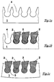
- FIGS. 1 a - 1 c The most important manufacturing steps of the method according to the invention are schematically recorded in FIGS. 1 a - 1 c.
- 1 a shows the part of a reinforcing element 1 with the recesses 4 which have already been introduced.
- a common method for producing such recesses is, for example, laser welding. To achieve higher precision, electrical erosion can also be useful.
- the reinforcing element contains a large number of such depressions in the production of the usual screening devices.
- Fig. 1 b three rods 2 are already inserted into the recesses, it being evident that the shape of the recess on the sides of the rod 2 leaves some air in each case. This makes it easy to insert the rod.
- the section in Fig. 2 shows a perspective view of part of the Reinforcing element 1, in which the rods 2 are inserted and already fastened therein. It can be seen that a slot sieve with the gaps 3 has formed through this arrangement, through which the liquid to be sorted can pass in the direction of flow (arrow S). In operation, parts the size of which exceed the free gap width are retained and removed in a manner known per se. A recess 4 for receiving a rod is shown here without the rod.
- the binder 5 indicated as a fat line can be introduced by soldering, welding or gluing. It forms a firm, non-detachable bond between the contact surfaces and thus decisively increases the strength of the screening device. In cases where the optimal cross-section of the bars was not chosen, e.g. because the sorting task required special shapes, the strength can still be high enough.
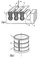
- the sieve device produced according to the invention can be designed as a cylindrical sieve basket which is held together by a plurality of annular reinforcing elements 1.
- the illustration shows only a part of the existing rods 2, which are inserted radially inside the rings here. Of course, these could also have been inserted outside.
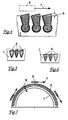
- the bars 2 will be inserted deeper or less deep into the reinforcing element 1. So, as shown in Fig. 4, almost completely recessed rods are also conceivable. This enables a particularly secure connection of rods 2 and reinforcing elements 1.
- the depressions 4 in the reinforcing elements 1 are designed as openings.
- the bars 2 have to be inserted laterally, whereby they have a hold even without deformation of the reinforcing element, e.g. if it is a press fit or a shrink fit. This is e.g. with tight fitting tolerances or with different temperatures of the joining partners when assembling.
- the profiles of the bars used can be freely selected according to the usage criteria (sorting technology) of the screening device. Another shape suitable for lateral insertion is shown in FIG. 6.
- FIG. 7 shows a section through a screening device designed as a half-shell.
- an arrangement is selected as an example in which the rods 2 are inserted on the radially outer part.
- the fixation could be carried out here by elastically bending the semi-ring-shaped reinforcing element 1 and releasing it after inserting the rods 2.
Landscapes
- Engineering & Computer Science (AREA)
- Manufacturing & Machinery (AREA)
- Mechanical Engineering (AREA)
- Paper (AREA)
- Combined Means For Separation Of Solids (AREA)
Abstract
Description
Die Erfindung bezieht sich auf ein Verfahren gemäß dem Oberbegriff des Anspruchs 1.The invention relates to a method according to the preamble of
Ein bekanntes Beispiel für den Einsatz von Siebvorrichtungen, die nach dem Verfahren dieser Art herstellbar sind, ist das Sortieren von Faserstoffsuspensionen. Dabei sollen die in der Suspension enthaltenen Fasern durch das Sieb hindurchtreten, während die nicht gewünschten festen Bestandteile an dem Spalt abgewiesen und aus der Siebvorrichtung wieder herausgeleitet werden. Denkbar ist auch ein Einsatz zur Trennung unterschiedlicher Faserbestandteile. Dadurch, daß die Öffnungen eine im wesentlichen längliche Form haben, also Schlitze oder Spalten sind, werden faserige Teilchen leichter durchgelassen als die kubischen, auch wenn beide Arten in ähnlicher Größenordnung vorliegen sollten. Mit einer derartigen Sortiertechnologie ist daher ein sehr guter Ausscheidungseffekt von naht faserigen Störstoffen aus Fasersuspensionen möglich. Voraussetzung ist allerdings eine hohe Präzision der Schlitzform auf der ganzen Siebfläche.A well-known example of the use of screening devices which can be produced by the method of this type is the sorting of fiber suspensions. The fibers contained in the suspension should pass through the sieve while the undesired solid constituents at the gap are rejected and led out of the sieve device. An application for the separation of different fiber components is also conceivable. The fact that the openings have an essentially elongated shape, that is to say slits or slits, allows fibrous particles to pass through more easily than cubic particles, even if both types should be of a similar size. With such a sorting technology, a very good separation effect of seam-fibrous interfering substances from fiber suspensions is possible. However, a prerequisite is a high precision of the slot shape on the entire screen surface.
Ein Verfahren, um solche Siebkörbe herzustellen, zeigt die DE 39 27 748 A1, bei der die Profilstäbe durch plastisches Verformen der mit Vertiefungen für die Stäbe vorgesehenen Halteringe eingeklemmt werden. Hierzu werden für derartige Herstellungsverfahren besonders geeignete Profilstäbe verwendet. Mit Hilfe dieses Verfahrens gelang es, die Herstellung wesentlich zu verbilligen, wobei aber Einschränkungen beim Einsatz solcher Siebkörbe nicht ganz auszuschließen waren.DE 39 27 748 A1 shows a method for producing such screen baskets, in which the profiled bars are clamped in by plastic deformation of the retaining rings provided with depressions for the bars. For this purpose, particularly suitable profile bars are used for such manufacturing processes. With the help of this method, it was possible to significantly reduce the cost of production, although restrictions in the use of such screen baskets could not be completely ruled out.
Siebe oder Siebkörbe mit guten Festigkeiten und hoher Oberflächengüte können nach einem Verfahren hergestellt werden, das in der DE 42 14 061 A1 beschrieben ist. Dabei wird zur Befestigung der stabartigen Profile ein Hochtemperatur-Lötverfahren angewendet. Die Ergebnisse sind ausgezeichnet, das Verfahren ist allerdings aufwendig und teuer.Sieves or sieve baskets with good strength and high surface quality can be produced by a process which is described in DE 42 14 061 A1. Here a high-temperature soldering process is used to attach the rod-like profiles. The results are excellent, but the process is complex and expensive.
Aus der Offenlegungsschrift DE 33 27 422 A1 sind Siebe oder Siebkörbe bekannt, bei denen die Sortierschlitze durch im wesentlichen parallele, stabartige Profile, die mit quer laufenden Halterippen verschweißt sind, gebildet werden. Auch wenn es durch dieses Fertigungsverfahren gelungen ist, die Stäbe mit den Halterippen fest zu verbinden, ist das bei der geforderten Präzision, wenn überhaupt, dann nur mit beträchtlichem Aufwand machbar. Um das Festsetzen von Fasern beim Betrieb der Siebvorrichtung zu vermeiden, müssen alle den Stoff berührenden Flächen extrem glatt sein. Nur so kann verhindert werden, daß sich Fasern dort aufbauen und früher oder später zu Verstopfung führen. Es hat zwar bereits Vorschläge gegeben, solche Schweißnähte nachträglich zu glätten oder abzudecken. Diese Maßnahmen waren aber meist geeignet, die Herstellung weiter zu verteuern.From the published patent application DE 33 27 422 A1, sieves or sieve baskets are known in which the sorting slots are formed by essentially parallel, rod-like profiles which are welded to transverse holding ribs. Even if this manufacturing process has succeeded in firmly connecting the rods to the retaining ribs, the required precision, if at all, can only be achieved with considerable effort. In order to avoid the sticking of fibers during the operation of the screening device, all surfaces that come into contact with the fabric must be extremely smooth. This is the only way to prevent fibers from building up there and leading to constipation sooner or later. There have already been proposals to subsequently smooth or cover such weld seams. However, these measures were mostly suitable to make production more expensive.
Der Erfindung liegt die Aufgabe zugrunde, ein wirtschaftlich günstiges Verfahren zu schaffen, mit dem Siebvorrichtungen herstellbar sind, die optimale Festigkeiten und Oberflächeneigenschaften haben.The invention has for its object to provide an economically advantageous method with which sieve devices can be produced that have optimal strength and surface properties.
Diese Aufgabe wird durch die im Kennzeichen des Anspruchs 1 genannten Maßnahmen erfüllt.This object is achieved by the measures mentioned in the characterizing part of
In Unteransprüchen sind vorteilhafte Ausgestaltungen des Verfahrens beschrieben sowie Siebvorrichtungen, die danach herstellbar sind.Advantageous refinements of the method are described in the subclaims, as are screening devices which can then be produced.
Die Vorteile der Erfindung wirken sich vor allem bei Stabsiebvorrichtungen aus, deren Sortierschlitze eine Weite in einem Größenbereich unter 2 mm haben. Für die Faserstoffsortierung oder -wäsche sind Schlitzweiten von 0,1 - 0,2 mm durchaus üblich. Derartige Siebe müssen mit einer sehr großen Anzahl von Stäben versehen sein, um bei den engen Schlitzen eine ausreichende Siebfläche zu erhalten. Daher ist bei ihrer Herstellung die Vorbereitung für das Zusammenfügen sehr aufwendig. Zwar ist es bei Serienfertigung möglich, spezielle Vorrichtungen einzusetzen, aber auch diese sind aufwendig und teuer. Bei dem erfindungsgemäße Verfahren dagegen werden die Profilstäbe z. B. durch einfaches Einschieben in ihre Position gebracht, fixiert und verbleiben darin, bis das Bindemittel für den endgültigen festen Halt gesorgt hat. Es wird also für eine Haltekraft der Stäbe in den Vertiefungen gesorgt, die groß genug ist, um die sich an das Einsetzen anschließenden Vorgänge des Handling ohne unbeabsichtigte Änderung der Position ausführen zu können. Dieses Handling umfaßt z.B. den Transport und das Wenden dieser Halbprodukte. Das Bindemittel stellt eine unlösbare Verbindung an den Kontaktflächen her, also wie z.B. beim Löten, Kleben oder Schweißen. Beim reinen Kontaktschweißen stammt dann das Bindemittel als Schmelze aus den Bauteilen selbst.The advantages of the invention have an effect particularly in the case of rod screen devices whose sorting slots have a width in a size range of less than 2 mm. Slit widths of 0.1 - 0.2 mm are quite common for fiber sorting or washing. Such screens have to be provided with a very large number of rods in order to obtain a sufficient screen area in the narrow slots. Therefore, with her Manufacturing the preparation for assembly is very complex. In series production it is possible to use special devices, but these are also complex and expensive. In the method according to the invention, however, the profile bars are z. B. brought into position by simple insertion, fixed and remain in it until the binder has provided the final firm hold. A holding force of the rods in the recesses is therefore provided which is large enough to be able to carry out the handling operations following the insertion without inadvertently changing the position. This handling includes, for example, the transport and turning of these semi-finished products. The binder creates an inseparable connection on the contact surfaces, such as when soldering, gluing or welding. In pure contact welding, the binder comes as a melt from the components themselves.
Ein mit Vorteil bei der Herstellung derartiger Siebvorrichtungen anwendbares Lötverfahren ist das Hartlöten bei einer Temperatur bis ca. 900o C. Man kann aber auch ein Verfahren bei hohen Temperaturen von etwa 1000 bis1200o C wählen, das im Hochvakuum durchgeführt wird. Die Verbindung der Materialien von Stäben und Verstärkungselementen erfolgt dabei durch Diffusion des Lotes in die zu verbindenden Bereiche, was sehr hohe Festigkeit bei makelloser Oberfläche bewirkt. Allerdings erfordert das letztgenannte Lötverfahren zunächst hohe Investitionen.Such a screening apparatus with advantage in the manufacture applicable soldering process the brazing at a temperature up to about 900 o C. It is but may also be a process at high temperatures of about 1000 to 1200 select o C, which is carried out in a high vacuum. The materials of rods and reinforcing elements are connected by diffusion of the solder into the areas to be connected, which results in very high strength with a flawless surface. However, the latter soldering process initially requires high investments.
Als preisgünstige Verbindung ist auch das Kleben anzusehen, da es bei relativ niedrigen Temperaturen durchführbar ist. Wird z.B. ein technischer Zwei-Komponenten-Klebstoff verwendet, bleiben die Klemmkräft erhalten. Dadurch kann z.B. die möglicherweise geringere Festigkeit der Klebeverbindung ausgeglichen werden. Verwendet man für die Stäbe gezogene Profile, etwa aus Stahl oder einer Stahllegierung, so sind auch spezielle Querschnittsformen wirtschaftlich und präzise erhältlich.Gluing can also be regarded as an inexpensive connection, since it can be carried out at relatively low temperatures. E.g. If a technical two-component adhesive is used, the clamping forces are retained. This can e.g. the possibly lower strength of the adhesive connection can be compensated. If drawn profiles are used for the rods, for example made of steel or a steel alloy, special cross-sectional shapes are also economically and precisely available.
Bei relativ engen Toleranzen an Vertiefungen und Stäben ist schon nach dem einfachen Einsetzen der Stäbe ein ausreichend fester Sitz möglich. Dann können Verstärkungselemente verwendet werden, die bereits beim Einlegen der Stäbe ihre endgültige Form haben. Diese etwas teurere Bearbeitung führt zu Siebvorrichtungen mit sehr gleichmäßigen Schlitzen, was besonders für ihren Einsatz zum Sortieren von Faserstoffsuspensionen für die Papierherstellung ein entscheidender Vorteil sein kann. Werden hingegen größere Passungstoleranzen zugelassen, was das Verfahren im allgemeinen verbilligt, ist eine Verformung der Verstärkungselemente nach dem Einsetzen der Stäbe erforderlich, um deren sicheren Halt zu gewährleisten. Die Klemmkräfte, die durch diese Verformung erzeugt worden sind, können während des Verfahrensschrittes, in dem die Bindemittel wirksam werden, schwächer werden oder wieder verloren gehen. Ein Nachteil für die fertig hergestellte Siebvorrichtung ist dadurch in der Regel aber nicht gegeben, weil bereits die Lötung zu ausgezeichneter Festigkeit führt. Hier ist das schon erwähnte Hochtemperatur-Löten unter Vakuum besonders gut geeignet.With relatively narrow tolerances on recesses and rods, a sufficiently tight fit is possible even after the rods are simply inserted. Then reinforcement elements can be used, which are already when the rods are inserted have final form. This somewhat more expensive processing leads to screening devices with very uniform slots, which can be a decisive advantage especially for their use for sorting fiber suspensions for paper production. If, on the other hand, larger fit tolerances are permitted, which generally reduces the cost of the method, the reinforcing elements must be deformed after the rods have been inserted in order to ensure their secure hold. The clamping forces generated by this deformation can become weaker or be lost again during the process step in which the binders take effect. As a rule, however, there is no disadvantage for the finished sieve device because the soldering already leads to excellent strength. The high-temperature soldering under vacuum mentioned above is particularly well suited here.
Ein Sonderfall ist die Aufweitung der Vertiefungen durch elastische Verformung der Verstärkungselemente, bevor die Stäbe eingelegt oder eingeschoben werden. Das führt nach der Entlastung, also der Rückverformung, zu einem sicheren Sitz und gleichzeitig guten Eigenschaften der so hergestellten Siebvorrichtung. Die Toleranzen müssen nicht so eng sein wie bei der ganz ohne Verformung arbeitenden Methode. Auch kann die elastische Verformung gering gehalten werden. Es reichen relativ geringe Haltekräfte aus, da lediglich die Position der Stäbe beim Handling gesichert werden soll.A special case is the widening of the depressions by elastic deformation of the reinforcing elements before the rods are inserted or inserted. After the relief, i.e. the reshaping, this leads to a secure fit and, at the same time, good properties of the screening device produced in this way. The tolerances do not have to be as narrow as with the method that works without deformation. The elastic deformation can also be kept low. Relatively low holding forces are sufficient since only the position of the bars is to be secured during handling.
Eine besonders wichtige Anwendung ist die Verwendung von geraden leistenförmigen Verstärkungselementen mit den bereits beschriebenen Vertiefungen. Nachdem in einer Art Mattenbildung die Stäbe eingeschoben worden sind, kann durch anschließendes Biegen, z.B. Rundwalzen der Verstärkungselemente die endgültige Form der Siebvorrichtung erzeugt werden. Im selben Arbeitsgang erfolgt das Einklemmen der Stäbe und damit ihre für den weiteren Herstellungsvorgang erforderliche Fixierung. Eine weitere Verbilligung des Verfahrens ist möglich, wenn die Vertiefungen in den Verstärkungselementen so gestaltet sind, daß die Stäbe senkrecht - eventuell mit Druckkräften - eingelegt werden können, also nicht von der Seite geschoben werden müssen. Die Fixierung der Stäbe in den Verstärkungselementen bis zum Abschluß des Herstellungsvorganges kann, muß aber nicht, anschließend durch Verformung der Verstärkungselemente erfolgen.A particularly important application is the use of straight strip-shaped reinforcing elements with the depressions already described. After the rods have been inserted in a kind of mat formation, the final shape of the screening device can be produced by subsequent bending, for example round rolling of the reinforcing elements. The rods are clamped in the same operation and thus their fixation required for the further manufacturing process. A further reduction in the cost of the method is possible if the depressions in the reinforcing elements are designed in such a way that the rods can be inserted vertically, possibly with compressive forces, so that they do not have to be pushed from the side. The fixation of the rods in the reinforcing elements until the end of the Manufacturing process can, but need not, then take place by deforming the reinforcing elements.
Die Erfindung wird erläutert anhand von Zeichnungen; dabei zeigen:
- Fig. 1a - 1c
- schematisch einige Herstellungsschritte bei Anwendung des Verfahrens;
- Fig. 2
- Teil einer erfindungsgemäßen Siebvorrichtung im Schnitt;
- Fig. 3
- einen zylindrischen Siebkorb;
- Fig. 4
bis 6 - jeweils Varianten der Stäbe und ihrer Anordnung;
- Fig. 7
- ein Halbschalen-Sieb im Schnitt.
- 1a-1c
- schematically some manufacturing steps using the method;
- Fig. 2
- Part of a screening device according to the invention in section;
- Fig. 3
- a cylindrical screen basket;
- 4 to 6
- variants of the rods and their arrangement;
- Fig. 7
- a half-shell sieve in section.
Die wichtigsten Herstellungsschritte des erfindungsgemäßen Verfahrens sind in den Figuren 1 a - 1 c schematisch aufgezeichnet. In Fig. 1a sieht man den Teil eines Verstärkungselementes 1 mit den bereits eingebrachten Vertiefungen 4. Ein gängiges Verfahren für das Herstellen solcher Vertiefungen ist z.B. das Laserschweißen, zur Erzielung von höherer Präzision kann auch Elektro-Erosion sinnvoll sein. Bei der Herstellung der üblichen Siebvorrichtungen enthält das Verstärkungselement eine große Anzahl solcher Vertiefungen.
In Fig. 1 b sind drei Stäbe 2 bereits in die Vertiefungen eingesetzt, wobei erkennbar ist, daß die Form der Vertiefung an den Seiten des Stabes 2 jeweils etwas Luft läßt. Dadurch läßt sich der Stab leicht einschieben. Diese Luft, mit der der Stab C in der Vertiefung 4 sitzt, ist übertrieben gezeichnet, um das Prinzip besser darstellen zu können. Sehr gut erkennbar ist auch, daß die Stäbe 2 an ihrer in das Verstärkungselement eingesetzten Seite Verdickungen haben, welche das Herausfallen der Stäbe zuverlässig verhindern. Anschließend wird das Verstärkungselement 1 so verformt, daß die Stäbe 2 festgeklemmt sind. Es folgt die festigkeitserhöhende Behandlung, z.B. Löten. Wenn das Bindemittel 5 ein Lot ist, wird eine feste unlösbare Verbindung zwischen den Teilen erreicht (siehe Fig. 1 c). Diese Darstellung ist nur schematisch, da solche Vorgänge, wie z.B. Löten unter Hochvakuum dem Fachmann bekannt sind.The most important manufacturing steps of the method according to the invention are schematically recorded in FIGS. 1 a - 1 c. 1 a shows the part of a reinforcing
In Fig. 1 b three
Der Ausschnitt in Fig. 2 zeigt in perspektivischer Darstellung einen Teil des Verstärkungselementes 1, in das die Stäbe 2 eingesetzt und darin bereits befestigt sind. Man erkennt, daß sich durch diese Anordnung ein Schlitzsieb mit den Spalten 3 gebildet hat, durch welche in Strömungslaufrichtung (Pfeil S) die zu sortierende Flüssigkeit hindurchtreten kann. Im Betrieb werden Teile, deren Größe die freie Spaltweite überschreiten, in an sich bekannter Weise zurückgehalten und abgeführt. Eine Vertiefung 4 zur Aufnahme eines Stabes ist hier ohne den Stab gezeichnet. Das als Fettlinie angedeutete Bindemittel 5 kann durch Löten, Schweißen oder Kleben eingebracht worden sein. Es bildet eine feste unlösbare Bindung der Kontaktflächen und erhöht so die Festigkeit der Siebvorrichtung entscheidend. In Fällen, bei denen kein für das Fügen optimaler Querschnitt der Stäbe gewählt wurde, z.B. weil die Sortieraufgabe besondere Formen erforderte, kann die Festigkeit dennoch groß genug sein.The section in Fig. 2 shows a perspective view of part of the Reinforcing
Die erfindungsgemäß hergestellte Siebvorrichtung kann gemäß Fig. 3 als zylindrischer Siebkorb ausgeführt sein, der durch mehrere ringförmige Verstärkungselemente 1 zusammengehalten wird. Die Darstellung zeigt nur einen Teil der vorhandenen Stäbe 2, die hier radial innen in die Ringe eingesetzt sind. Selbstverständlich könnten diese auch außen eingefügt worden sein.According to FIG. 3, the sieve device produced according to the invention can be designed as a cylindrical sieve basket which is held together by a plurality of annular reinforcing
Je nach Anforderungen und Fertigungsmöglichkeiten werden die Stäbe 2 tiefer oder weniger tief in das Verstärkungselement 1 eingefügt sein. So sind auch, wie in Fig. 4 gezeigt, fast vollständig versenkte Stäbe denkbar. Dies ermöglicht eine besonders sichere Verbindung von Stäben 2 und Verstärkungselementen 1.Depending on the requirements and production possibilities, the
In vielen Fällen ist es von Vorteil, wenn die der Anströmung zugewandten Flächen der Stäbe 2 gegen die Bewegungsrichtung (Pfeil 7) des Räumelementes 8 (nur angedeutet) geneigt sind, so daß sich an der Hinterkante der Stäbe Absätze 6 bilden. An dieser Stelle können mit Hilfe der vorbeibewegten Räumungsflügel Wirbel erzeugt werden, die die Räumungswirkung verbessern. Mit Räumen ist gemeint, daß die Stoff-Wasser-Suspension wieder ausreichend fluidisiert und die abgewiesenen Teile möglichst schnell aus diesem Siebbereich entfernt werden, so daß die Siebfläche wieder zur weiteren Siebung angeboten wird.In many cases it is advantageous if the surfaces of the
In Fig. 5 sind die Vertiefungen 4 in den Verstärkungselementen 1 als Öffnungen ausgebildet. In solchen Fällen müssen die Stäbe 2 seitlich durchgesteckt werden, wobei sie auch ohne Verformung des Verstärkungselementes einen Halt haben, z.B. wenn es sich um einen Preßsitz oder einen Schrumpfsitz handelt. Dieser wird z.B. mit engen Paßtoleranzen oder mit unterschiedlicher Temperatur der Fügepartner beim Zusammensetzen erzeugt. Die verwendeten Profile der Stäbe können frei nach Verwendungskriterien (Sortier-Technologie) der Siebvorrichtung gewählt werden. Eine andere für das seitliche Durchstecken geeignete Form zeigt Fig. 6.5, the
In Fig. 7 wird ein Schnitt durch eine als Halbschale ausgebildete Siebvorrichtung gezeigt. Dabei ist hier exemplarisch eine Anordnung gewählt, bei der die Stäbe 2 am radial äußeren Teil eingesetzt sind. Die Fixierung könnte hier durchgeführt werden, indem das halbringförmige Verstärkungselement 1 elastisch zusammengebogen und nach Einlegen der Stäbe 2 wieder freigegeben wird.7 shows a section through a screening device designed as a half-shell. Here, an arrangement is selected as an example in which the
Es versteht sich, daß durch die Wahl des Stabquerschnittes und durch die Art, diesen in die Befestigungselemente einzufügen, zur Gestaltung des Sortierspaltes eine große Anzahl von Möglichkeiten gegeben ist.It goes without saying that the choice of the rod cross section and the way in which it is inserted into the fastening elements provide a large number of possibilities for designing the sorting gap.
Claims (19)
dadurch gekennzeichnet,
daß
characterized by
that
dadurch gekennzeichnet,
daß die Sortierspalte (3) an ihrer engsten Stelle höchstens 3 mm breit sind.Method according to claim 1,
characterized by
that the sorting column (3) is at most 3 mm wide at its narrowest point.
dadurch gekennzeichnet,
daß die Sortierspalte (3) an ihrer engsten Stelle höchstens 0,4 mm breit sind.Method according to claim 2,
characterized by
that the sorting gaps (3) are at most 0.4 mm wide at their narrowest point.
dadurch gekennzeichnet,
daß sich die Vertiefungen (4) in den Verstärkungselementen (1) ausgehend von der mit den Vertiefungen (4) versehenen Oberfläche nach innen hin anfangs verjüngen und weiter innen wieder erweitern.The method of claim 1, 2 or 3,
characterized by
that the depressions (4) in the reinforcing elements (1), starting from the surface provided with the depressions (4), initially taper inwards and expand further inwards.
dadurch gekennzeichnet,
daß der Querschnitt der Stäbe (2) eine Form aufweist, die aus einem Dreieck mit abgerundeten Kanten gebildet ist, welches an der in das Verstärkungselement (1) eingelassenen Firstseite eine Verdickung aufweist.The method of claim 1, 2, 3 or 4,
characterized by
that the cross section of the rods (2) has a shape which is formed from a triangle with rounded edges, which has a thickened portion on the ridge side let into the reinforcing element (1).
dadurch gekennzeichnet,
daß die Stäbe (2) so geformt und eingesetzt werden, daß die Sortierschlitze ausgehend von der engsten Stelle einen sich in Flußrichtung erweiternden Strömungsquerschnitt bilden.Method according to one of the preceding claims,
characterized by
that the rods (2) are shaped and inserted in such a way that the sorting slots, starting from the narrowest point, form a flow cross section which widens in the flow direction.
dadurch gekennzeichnet,
daß das Bindemittel (5) ein Lot ist.Method according to one of the preceding claims,
characterized by
that the binder (5) is a solder.
dadurch gekennzeichnet,
daß beim Löten eine Temperatur unter 900o C eingestellt wird.Method according to claim 7,
characterized by
that a temperature below 900 o C is set during soldering.
dadurch gekennzeichnet,
daß beim Löten eine Temperatur über 900o C eingestellt und ein Hochvakuum aufgebaut wird.Method according to claim 7,
characterized by
that a temperature above 900 o C is set during soldering and a high vacuum is built up.
dadurch gekennzeichnet,
daß das Bindemittel ein Klebstoff ist.Method according to one of claims 1 to 6,
characterized by
that the binder is an adhesive.
dadurch gekennzeichnet,
daß in der Verbindungsstelle eine Reaktionstemperatur von 200o C nicht überschritten wird.Method according to claim 10 or one of claims 1 to 6,
characterized by
that a reaction temperature of 200 o C is not exceeded in the connection point.
dadurch gekennzeichnet,
daß als Bindemittel eine Schweißverbindung dient.Method according to one of claims 1 to 6,
characterized by
that a welded joint serves as a binding agent.
dadurch gekennzeichnet,
daß die Verstärkungselemente (1) während des Einsetzens der Stäbe (2) noch nicht die endgültige Form haben, sondern erst nach dem Einsetzen so verformt werden, daß die Siebvorrichtung die beabsichtigte Gestalt annimmt.Method according to one of the preceding claims,
characterized by
that the reinforcing elements (1) do not yet have the final shape during the insertion of the rods (2), but are only deformed after the insertion in such a way that the sieve device assumes the intended shape.
dadurch gekennzeichnet,
daß die Stäbe (2) beim Verformen der Verstärkungselemente (1) in den Vertiefungen eingeklemmt werden.A method according to claim 13,
characterized by
that the rods (2) are clamped in the depressions when the reinforcing elements (1) are deformed.
dadurch gekennzeichnet,
daß die Verstärkungselemente (1) während des Einsetzens der Stäbe (2) ebene Leisten sind und nach dem Einsetzen der Stäbe zu Ringen oder Ringsegmenten gebogen werden.The method of claim 14
characterized by
that the reinforcing elements (1) are flat strips during the insertion of the bars (2) and are bent into rings or ring segments after the bars are inserted.
dadurch gekennzeichnet,
daß die Stäbe in diesen Vertiefungen (4) durch ein Bindemittel (5) mit den Verstärkungselementen (1) unlösbar verbunden sind.Screening device, produced with the method according to one of the preceding claims, with slot-shaped openings for sorting fiber suspensions with a plurality of essentially parallel bars (2) between which there are the sorting gaps (3) or sorting slots and which are positively in reinforcing elements ( 1) are fixed, the reinforcing elements (1) being depressions (4) for receiving the rods (2) have and connect several or all of the rods (2) present on the screening device,
characterized by
that the rods in these recesses (4) by a binder (5) with the reinforcing elements (1) are inextricably linked.
dadurch gekennzeichnet,
daß die Stäbe (2) aus einem gezogenen Profil bestehen.Screening device according to claim 16,
characterized by
that the rods (2) consist of a drawn profile.
dadurch gekennzeichnet,
daß die Stäbe (2) aus einem gewalzten Profil bestehen.Screening device according to claim 16,
characterized by
that the rods (2) consist of a rolled profile.
dadurch gekennzeichnet,
daß die Stäbe (2) durch einen Preßsitz in den Verstärkungselementen (1) fixiert sind.Screening device according to claim 16,
characterized by
that the rods (2) are fixed by a press fit in the reinforcing elements (1).
Applications Claiming Priority (4)
| Application Number | Priority Date | Filing Date | Title |
|---|---|---|---|
| DE29609298U DE29609298U1 (en) | 1996-05-24 | 1996-05-24 | Screening device with slit-shaped openings |
| DE29609298U | 1996-05-24 | ||
| DE19709582A DE19709582C2 (en) | 1996-05-24 | 1997-03-08 | Process for producing a screen device with slit-shaped openings |
| DE19709582 | 1997-03-08 |
Publications (2)
| Publication Number | Publication Date |
|---|---|
| EP0808941A1 true EP0808941A1 (en) | 1997-11-26 |
| EP0808941B1 EP0808941B1 (en) | 2001-12-12 |
Family
ID=26034649
Family Applications (1)
| Application Number | Title | Priority Date | Filing Date |
|---|---|---|---|
| EP97104439A Revoked EP0808941B1 (en) | 1996-05-24 | 1997-03-15 | Process to make a screening apparatus having slotted apertures and screening apparatus obtained by this process |
Country Status (4)
| Country | Link |
|---|---|
| US (1) | US6047834A (en) |
| EP (1) | EP0808941B1 (en) |
| AT (1) | ATE210756T1 (en) |
| CA (1) | CA2203325C (en) |
Cited By (5)
| Publication number | Priority date | Publication date | Assignee | Title |
|---|---|---|---|---|
| WO2001061104A1 (en) * | 2000-02-19 | 2001-08-23 | Hermann Finckh Maschinenfabrik Gmbh & Co. | Sieve for fibre suspensions and a method for producing same |
| WO2008119548A3 (en) * | 2007-04-02 | 2009-01-15 | Andritz Fiedler Gmbh | Sifting device |
| EP1825933A3 (en) * | 2006-02-22 | 2011-03-09 | Voith Patent GmbH | Method for the manufacture of a rotation symmetric screening device, in particular a cylindrical, screening device |
| EP1825932A3 (en) * | 2006-02-22 | 2011-03-09 | Voith Paper Patent GmbH | Method for the manufacture of a rotation symmetric screening device , in particular a cylindrical, screening device |
| EP2663688A4 (en) * | 2011-01-13 | 2014-06-25 | Georgia Pacific Consumer Prod | Screen basket optimized for removal of stickies from adhesives-contaminated recyclable fiber |
Families Citing this family (12)
| Publication number | Priority date | Publication date | Assignee | Title |
|---|---|---|---|---|
| FR2809029B1 (en) * | 2000-05-16 | 2002-06-21 | Johnson Filtration Systems | METHOD FOR MANUFACTURING A MECHANICAL FILTRATION BASKET |
| IT1315545B1 (en) * | 2000-11-13 | 2003-02-18 | Comer Spa | METHOD FOR THE MANUFACTURE OF FILTER BASKETS FOR MACHINES DIFILTRATION OF FIBERS IN Aqueous SUSPENSION AND FILTER BASKET |
| FI119440B (en) * | 2004-07-16 | 2008-11-14 | Advanced Fiber Tech Aft Trust | Process for manufacturing a screen cylinder and a screen cylinder |
| JP4376151B2 (en) * | 2004-08-09 | 2009-12-02 | 相川鉄工株式会社 | Screen device |
| WO2006119614A1 (en) * | 2005-05-09 | 2006-11-16 | Hetu Marc-Andre | Screen basket with replaceable profiled bars |
| MX2010005202A (en) * | 2007-11-14 | 2010-11-12 | Filtration Fibrewall Inc | Screen basket. |
| US20090211965A1 (en) * | 2008-02-21 | 2009-08-27 | Weatherford/Lamb, Inc. | Arrangement for splicing panels together to form a cylindrical screen |
| US8028691B2 (en) | 2008-10-27 | 2011-10-04 | Johnson Screens, Inc. | Passive solar wire screens for buildings |
| US9023456B2 (en) | 2011-03-18 | 2015-05-05 | Bilfinger Water Technologies, Inc. | Profiled wire screen for process flow and other applications |
| DE102014011679A1 (en) | 2013-08-20 | 2015-02-26 | Andritz Fiedler Gmbh | Profiled sieve and sieve device made of profiled sieve bars |
| JP6460741B2 (en) * | 2014-08-06 | 2019-01-30 | 相川鉄工株式会社 | Papermaking strainer and papermaking foreign matter separating device |
| US10513825B2 (en) | 2017-09-18 | 2019-12-24 | Ahmed Ibrahim | Paper manufacturing system |
Citations (7)
| Publication number | Priority date | Publication date | Assignee | Title |
|---|---|---|---|---|
| US1937274A (en) * | 1931-03-12 | 1933-11-28 | Brown Co | Screen plate |
| DE3327422A1 (en) * | 1983-07-29 | 1985-02-07 | J.M. Voith Gmbh, 7920 Heidenheim | Screen, especially for sorting fibre suspensions produced on the basis of waste paper |
| US4846971A (en) * | 1984-11-12 | 1989-07-11 | E&M Lamort | Sieves for scrubbers and their method of manufacture |
| US5011065A (en) * | 1987-11-14 | 1991-04-30 | J.M. Voith Gmbh | Screen basket and method of manufacture |
| US5094360A (en) * | 1989-08-23 | 1992-03-10 | J. M. Voith Gmbh | Screen basket |
| DE4214061A1 (en) * | 1992-04-29 | 1993-11-04 | Escher Wyss Gmbh | SCREEN DEVICE |
| US5394600A (en) * | 1994-02-14 | 1995-03-07 | Chen; Chao-Ho | Method for making a screen |
Family Cites Families (3)
| Publication number | Priority date | Publication date | Assignee | Title |
|---|---|---|---|---|
| DE59004134D1 (en) * | 1989-12-09 | 1994-02-17 | Escher Wyss Gmbh | Process for producing a slotted screen. |
| JP3396246B2 (en) * | 1993-01-18 | 2003-04-14 | 株式会社ナガオカ | Multilayer composite screen |
| US5387340A (en) * | 1993-07-15 | 1995-02-07 | Ackerman; Carl D. | Wire filter element and method of manufacture |
-
1997
- 1997-03-15 AT AT97104439T patent/ATE210756T1/en not_active IP Right Cessation
- 1997-03-15 EP EP97104439A patent/EP0808941B1/en not_active Revoked
- 1997-04-22 CA CA002203325A patent/CA2203325C/en not_active Expired - Fee Related
- 1997-04-23 US US08/839,181 patent/US6047834A/en not_active Expired - Lifetime
Patent Citations (7)
| Publication number | Priority date | Publication date | Assignee | Title |
|---|---|---|---|---|
| US1937274A (en) * | 1931-03-12 | 1933-11-28 | Brown Co | Screen plate |
| DE3327422A1 (en) * | 1983-07-29 | 1985-02-07 | J.M. Voith Gmbh, 7920 Heidenheim | Screen, especially for sorting fibre suspensions produced on the basis of waste paper |
| US4846971A (en) * | 1984-11-12 | 1989-07-11 | E&M Lamort | Sieves for scrubbers and their method of manufacture |
| US5011065A (en) * | 1987-11-14 | 1991-04-30 | J.M. Voith Gmbh | Screen basket and method of manufacture |
| US5094360A (en) * | 1989-08-23 | 1992-03-10 | J. M. Voith Gmbh | Screen basket |
| DE4214061A1 (en) * | 1992-04-29 | 1993-11-04 | Escher Wyss Gmbh | SCREEN DEVICE |
| US5394600A (en) * | 1994-02-14 | 1995-03-07 | Chen; Chao-Ho | Method for making a screen |
Cited By (9)
| Publication number | Priority date | Publication date | Assignee | Title |
|---|---|---|---|---|
| WO2001061104A1 (en) * | 2000-02-19 | 2001-08-23 | Hermann Finckh Maschinenfabrik Gmbh & Co. | Sieve for fibre suspensions and a method for producing same |
| US6789681B2 (en) | 2000-02-19 | 2004-09-14 | Voith Paper Patent Gmbh | Screen for fiber suspensions and method for the manufacture thereof |
| EP1825933A3 (en) * | 2006-02-22 | 2011-03-09 | Voith Patent GmbH | Method for the manufacture of a rotation symmetric screening device, in particular a cylindrical, screening device |
| EP1825932A3 (en) * | 2006-02-22 | 2011-03-09 | Voith Paper Patent GmbH | Method for the manufacture of a rotation symmetric screening device , in particular a cylindrical, screening device |
| WO2008119548A3 (en) * | 2007-04-02 | 2009-01-15 | Andritz Fiedler Gmbh | Sifting device |
| US8292086B2 (en) | 2007-04-02 | 2012-10-23 | Andritz Fiedler Gmbh | Strainer apparatus |
| CN101657269B (en) * | 2007-04-02 | 2014-04-23 | 安德里兹·菲德勒有限责任公司 | filter |
| EP2129477B1 (en) | 2007-04-02 | 2015-07-08 | Andritz Fiedler Gmbh | Sifting device |
| EP2663688A4 (en) * | 2011-01-13 | 2014-06-25 | Georgia Pacific Consumer Prod | Screen basket optimized for removal of stickies from adhesives-contaminated recyclable fiber |
Also Published As
| Publication number | Publication date |
|---|---|
| ATE210756T1 (en) | 2001-12-15 |
| EP0808941B1 (en) | 2001-12-12 |
| CA2203325C (en) | 2003-06-10 |
| CA2203325A1 (en) | 1997-11-24 |
| US6047834A (en) | 2000-04-11 |
Similar Documents
| Publication | Publication Date | Title |
|---|---|---|
| EP0808941B1 (en) | Process to make a screening apparatus having slotted apertures and screening apparatus obtained by this process | |
| DE69615414T2 (en) | SCREENING DEVICE LIKE A SCREENING CYLINDER AND METHOD FOR PRODUCING THE SCREENING DEVICE | |
| EP0499154B1 (en) | Screen drum | |
| EP0705649B1 (en) | Method for manufacturing a flat or centripetal screen | |
| EP0837178B1 (en) | Process for making screens and screen obtained by this method | |
| EP0316570A2 (en) | Screen drum and method of manufacturing same | |
| EP1297218A1 (en) | Sieve for fibre suspensions and a method for producing same | |
| DE69823558T2 (en) | METHOD FOR PRODUCING A SIEVE CYLINDER AND SIEVE CYLINDER | |
| EP1825932A2 (en) | Method for the manufacture of a rotation symmetric screening device , in particular a cylindrical, screening device | |
| DE19651643A1 (en) | Sieve for sorting out suspended fibres | |
| DE4214061C2 (en) | Screening device | |
| EP1122359B1 (en) | Screen and method for manufacturing the same | |
| EP1825933A2 (en) | Method for the manufacture of a rotation symmetric screening device, in particular a cylindrical, screening device | |
| DE69501491T2 (en) | Process for producing a screen cylinder and screen cylinder produced therewith | |
| EP4048450B1 (en) | Screening cylinder | |
| DE19709582C2 (en) | Process for producing a screen device with slit-shaped openings | |
| DE19547585A1 (en) | Sieving element | |
| DE602004006611T2 (en) | Strainer basket for filtering fiber suspensions and process for its preparation | |
| DE3015370C2 (en) | Screen basket for sorters in the paper industry | |
| DE3790016C2 (en) | ||
| EP0989897B1 (en) | Bar screen basket for fiber suspensions and method for the production thereof | |
| DE19836316C2 (en) | Process for the production of curved sieves | |
| EP1875970A1 (en) | Method for manufacturing sieves and sieve manufactured accordingly | |
| DE19625726C1 (en) | Wire unit has sorting gaps for fibre suspension | |
| DE10247166A1 (en) | Process to make paper sorting sieve with three parallel rods separated by narrow gap and transposed and tensioned in position prior to welding |
Legal Events
| Date | Code | Title | Description |
|---|---|---|---|
| PUAI | Public reference made under article 153(3) epc to a published international application that has entered the european phase |
Free format text: ORIGINAL CODE: 0009012 |
|
| AK | Designated contracting states |
Kind code of ref document: A1 Designated state(s): AT DE FI FR GB NL SE |
|
| 17P | Request for examination filed |
Effective date: 19980526 |
|
| 17Q | First examination report despatched |
Effective date: 20000531 |
|
| GRAG | Despatch of communication of intention to grant |
Free format text: ORIGINAL CODE: EPIDOS AGRA |
|
| GRAG | Despatch of communication of intention to grant |
Free format text: ORIGINAL CODE: EPIDOS AGRA |
|
| GRAH | Despatch of communication of intention to grant a patent |
Free format text: ORIGINAL CODE: EPIDOS IGRA |
|
| GRAH | Despatch of communication of intention to grant a patent |
Free format text: ORIGINAL CODE: EPIDOS IGRA |
|
| GRAA | (expected) grant |
Free format text: ORIGINAL CODE: 0009210 |
|
| AK | Designated contracting states |
Kind code of ref document: B1 Designated state(s): AT DE FI FR GB NL SE |
|
| REF | Corresponds to: |
Ref document number: 210756 Country of ref document: AT Date of ref document: 20011215 Kind code of ref document: T |
|
| REG | Reference to a national code |
Ref country code: GB Ref legal event code: IF02 |
|
| GBT | Gb: translation of ep patent filed (gb section 77(6)(a)/1977) |
Effective date: 20011212 |
|
| REF | Corresponds to: |
Ref document number: 59705733 Country of ref document: DE Date of ref document: 20020124 |
|
| ET | Fr: translation filed | ||
| PLBQ | Unpublished change to opponent data |
Free format text: ORIGINAL CODE: EPIDOS OPPO |
|
| PLBI | Opposition filed |
Free format text: ORIGINAL CODE: 0009260 |
|
| PLBF | Reply of patent proprietor to notice(s) of opposition |
Free format text: ORIGINAL CODE: EPIDOS OBSO |
|
| 26 | Opposition filed |
Opponent name: ADVANCED FIBER TECHNOLOGIES OY Effective date: 20020830 |
|
| NLR1 | Nl: opposition has been filed with the epo |
Opponent name: ADVANCED FIBER TECHNOLOGIES OY |
|
| PLBF | Reply of patent proprietor to notice(s) of opposition |
Free format text: ORIGINAL CODE: EPIDOS OBSO |
|
| PGFP | Annual fee paid to national office [announced via postgrant information from national office to epo] |
Ref country code: DE Payment date: 20030403 Year of fee payment: 7 |
|
| PGFP | Annual fee paid to national office [announced via postgrant information from national office to epo] |
Ref country code: GB Payment date: 20040227 Year of fee payment: 8 |
|
| RDAF | Communication despatched that patent is revoked |
Free format text: ORIGINAL CODE: EPIDOSNREV1 |
|
| PGFP | Annual fee paid to national office [announced via postgrant information from national office to epo] |
Ref country code: FR Payment date: 20040322 Year of fee payment: 8 |
|
| PGFP | Annual fee paid to national office [announced via postgrant information from national office to epo] |
Ref country code: NL Payment date: 20040323 Year of fee payment: 8 Ref country code: AT Payment date: 20040323 Year of fee payment: 8 |
|
| PGFP | Annual fee paid to national office [announced via postgrant information from national office to epo] |
Ref country code: FI Payment date: 20040324 Year of fee payment: 8 |
|
| PGFP | Annual fee paid to national office [announced via postgrant information from national office to epo] |
Ref country code: SE Payment date: 20040325 Year of fee payment: 8 |
|
| RDAG | Patent revoked |
Free format text: ORIGINAL CODE: 0009271 |
|
| STAA | Information on the status of an ep patent application or granted ep patent |
Free format text: STATUS: PATENT REVOKED |
|
| 27W | Patent revoked |
Effective date: 20040329 |
|
| GBPR | Gb: patent revoked under art. 102 of the ep convention designating the uk as contracting state |
Free format text: 20040329 |
|
| REG | Reference to a national code |
Ref country code: SE Ref legal event code: ECNC |
|
| NLR2 | Nl: decision of opposition |
Effective date: 20040329 |