EP0989291B1 - Einrichtung zur Kontaktierung einer Platine - Google Patents
Einrichtung zur Kontaktierung einer Platine Download PDFInfo
- Publication number
- EP0989291B1 EP0989291B1 EP99118492A EP99118492A EP0989291B1 EP 0989291 B1 EP0989291 B1 EP 0989291B1 EP 99118492 A EP99118492 A EP 99118492A EP 99118492 A EP99118492 A EP 99118492A EP 0989291 B1 EP0989291 B1 EP 0989291B1
- Authority
- EP
- European Patent Office
- Prior art keywords
- circuit board
- contacts
- holding part
- board
- spring element
- Prior art date
- Legal status (The legal status is an assumption and is not a legal conclusion. Google has not performed a legal analysis and makes no representation as to the accuracy of the status listed.)
- Expired - Lifetime
Links
- 238000002485 combustion reaction Methods 0.000 claims description 5
- 239000004020 conductor Substances 0.000 claims description 2
- 239000000463 material Substances 0.000 claims description 2
- 230000001276 controlling effect Effects 0.000 description 2
- 238000004519 manufacturing process Methods 0.000 description 2
- 230000036316 preload Effects 0.000 description 2
- 238000003860 storage Methods 0.000 description 2
- 238000003466 welding Methods 0.000 description 2
- 238000005352 clarification Methods 0.000 description 1
- 230000006378 damage Effects 0.000 description 1
- 239000011888 foil Substances 0.000 description 1
- 238000005304 joining Methods 0.000 description 1
- 238000000034 method Methods 0.000 description 1
- 230000000149 penetrating effect Effects 0.000 description 1
- 230000001105 regulatory effect Effects 0.000 description 1
- 238000007493 shaping process Methods 0.000 description 1
- 229910000679 solder Inorganic materials 0.000 description 1
Images

Classifications
-
- F—MECHANICAL ENGINEERING; LIGHTING; HEATING; WEAPONS; BLASTING
- F02—COMBUSTION ENGINES; HOT-GAS OR COMBUSTION-PRODUCT ENGINE PLANTS
- F02D—CONTROLLING COMBUSTION ENGINES
- F02D45/00—Electrical control not provided for in groups F02D41/00 - F02D43/00
-
- F—MECHANICAL ENGINEERING; LIGHTING; HEATING; WEAPONS; BLASTING
- F02—COMBUSTION ENGINES; HOT-GAS OR COMBUSTION-PRODUCT ENGINE PLANTS
- F02D—CONTROLLING COMBUSTION ENGINES
- F02D11/00—Arrangements for, or adaptations to, non-automatic engine control initiation means, e.g. operator initiated
- F02D11/06—Arrangements for, or adaptations to, non-automatic engine control initiation means, e.g. operator initiated characterised by non-mechanical control linkages, e.g. fluid control linkages or by control linkages with power drive or assistance
- F02D11/10—Arrangements for, or adaptations to, non-automatic engine control initiation means, e.g. operator initiated characterised by non-mechanical control linkages, e.g. fluid control linkages or by control linkages with power drive or assistance of the electric type
-
- F—MECHANICAL ENGINEERING; LIGHTING; HEATING; WEAPONS; BLASTING
- F02—COMBUSTION ENGINES; HOT-GAS OR COMBUSTION-PRODUCT ENGINE PLANTS
- F02D—CONTROLLING COMBUSTION ENGINES
- F02D9/00—Controlling engines by throttling air or fuel-and-air induction conduits or exhaust conduits
- F02D9/02—Controlling engines by throttling air or fuel-and-air induction conduits or exhaust conduits concerning induction conduits
- F02D2009/0201—Arrangements; Control features; Details thereof
- F02D2009/0294—Throttle control device with provisions for actuating electric or electronic sensors
Definitions
- the invention relates to a device for contacting a circuit board electronic control device of an actuator, in particular a throttle valve an internal combustion engine of a motor vehicle, the control device and the actuator form a structural unit, with on a first Board arranged contacts and connected to a second board, contacts conductively connected to the contacts of the first circuit board.
- Throttle valves used are usually one or more electronic circuit boards Control device arranged in a pot-shaped housing.
- the housing is in one piece with a throttle body that supports the throttle valve manufactured and is closed by a lid.
- the throttle body has a flange for direct screwing to the internal combustion engine.
- connection contacts for the vehicle electrical system and for Signal lines arranged. This makes the throttle body with all components required to regulate the output, such as the circuit boards and the Lid with the connection contacts very compact.
- the circuit boards and the connection contacts of the cover are on their contacts electrically contacted with each other and with a servomotor for the throttle valve. Because the contacting in particular in the throttle body the printed circuit boards withstand high temperatures and vibrations the contacts are usually connected to each other by laser welding. However, laser welding is very complex and leads to a very high level costly assembly of the throttle body.
- the invention is based on the problem of a device of the type mentioned Art to design so that the electrical connection of the contacts designed as inexpensively as possible and that the connection then high Withstands temperatures and vibrations particularly reliably.
- the circuit board is contacted in an area in which there are no mechanical loads on the connection point. Therefore, vibrations do not cause the contacts to rub against each other and not to destroy them. Tolerances between the components and Relative movements of the components to each other are from the connecting lines balanced.
- the contact device according to the invention thus has a particularly high reliability. As for the contact device according to the invention no solder joints are required, this is especially for use suitable for internal combustion engines of motor vehicles.
- the pretensioning of the holding part could, for example, be one on the first Printed circuit board arranged bracket.
- the holding part is an additional step when joining the boards together required.
- the holding part is preloaded according to an advantageous method Further development of the invention without additional assembly effort when Assemble the boards when between the second board and the Holding part a spring element for biasing the holding part against the first Circuit board is arranged.
- the device according to the invention is particularly cost-effective, if the elastic connecting cables are printed on a foil Conductor tracks are formed.
- the manufacture of the holding part as a separate component only leads to an insignificant one Increasing the manufacturing costs of the device according to the invention, if the holding part and the second board are made of the same plastic and with each other via a thin bridge in relation to their material thickness are connected.
- the web can optionally be used as a predetermined breaking point between the second board and the holding part serve, or elastically, a relative movement the components are designed to enable each other.
- a relative movement of the holding part with respect to the first board can be according to another advantageous development of the invention, simply avoid if the holding part guide pin and the first component the guide pin has corresponding holes.
- the holding part is according to another advantageous development of the invention reliably biased against the first board when the second board has a guide element for the spring element.
- the device according to the invention is structurally particularly simple, if the spring element is a helical spring and the guide element is a sleeve is.
- the contacts could each be designed as contact plates, for example his. Opposing contact plates could be used for contacting pretension vertically against each other.
- this design requires very high preload forces to avoid friction between the contacts and a particularly precise guidance of the holding part with respect to the first Circuit board. Friction between the contacts would result in destruction of the electrically conductive connection. A friction between the contacts
- the contacts of the second board are pin-shaped and the contacts of the first board against the contacts of the second board are biased.
- the side preload can be very simple by appropriate shaping of the contacts of the first board respectively.
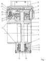
- FIG. 1 shows a throttle valve connector 1 with a load adjusting device 2.
- the load adjustment device 2 has a channel 3 penetrating Control shaft 4.
- On the control shaft 4 is one for controlling a free cross-sectional area of the channel 3 serving throttle valve 5 attached.
- the control shaft 4 is of a in a cup-shaped housing 6 of the throttle body 1 arranged actuator 7 pivoted. Furthermore is in the housing 6 a control device 8 for controlling an electric motor, not shown arranged.
- the actuator 7 can be driven with the electric motor and thus pivot the control shaft 4.
- the cup-shaped housing 6 of the throttle valve connector 1 is closed by a cover 9.
- the throttle valve connector 1 has two bearings 10, 11 for the actuating shaft 4 on. At the end of the control shaft 4 opposite the control gear 7 a control lever 12 attached. To the bearing 11 of this end of the control shaft 4th an emergency running spring 13 and a return spring 14 are arranged concentrically. The return spring 14 and the emergency running spring 13 are each in the form of leg springs designed and arranged in a shaft-like housing 15. The housing 15 is closed by a cover 16.
- the control device has two boards 17, 18 arranged one above the other the cover 9, a socket 19 is arranged with which the control device 8 to a vehicle electrical system, not shown, for the power supply and / or for data exchange (for example via a CAN bus) is connected.
- the two boards 17, 18 are with an inventive Device 23 electrically connected to each other.
- a holding part 20 is arranged between the two Boards 17, 18, a holding part 20 is arranged.
- the holding part 20 is one spring element 21 designed as a helical spring against upper board 18 biased and is with elastic connecting lines 22 to the lower board 17 connected.
- the device 23 according to the invention is greatly enlarged in one Partial section through the holding part 20 and a partial area of the upper board 18 shown.
- the electrical connection lines 22 are up to on the holding part 20 arranged contacts 24 out.
- the contacts 24 of the holding part 20 are connected to contacts 25 of the upper board 18.
- Figure 2 shows that the spring element 21 by a as Sleeve trained guide element 26 is guided vertically.
Landscapes
- Engineering & Computer Science (AREA)
- Chemical & Material Sciences (AREA)
- Combustion & Propulsion (AREA)
- Mechanical Engineering (AREA)
- General Engineering & Computer Science (AREA)
- Control Of Throttle Valves Provided In The Intake System Or In The Exhaust System (AREA)
- Coupling Device And Connection With Printed Circuit (AREA)
Description
- Figur 1:
- einen Drosselklappenstutzen mit einer Steuereinrichtung in einem Längsschnitt,
- Figur 2:
- eine vergrößerte Darstellung einer erfindungsgemäßen Einrichtung aus Figur 1.
- 1.
- Drosselklappenstutzen
- 2.
- Lastverstellvorrichtung
- 3.
- Kanal
- 4.
- Stellwelle
- 5.
- Drosselklappe
- 6.
- Gehäuse
- 7.
- Stellgetriebe
- 8.
- Steuerelektronik
- 9.
- Deckel
- 10.
- Lagerung
- 11.
- Lagerung
- 12.
- Stellhebel
- 13.
- Notlauffeder
- 14.
- Rückstellfeder
- 15.
- Gehäuse
- 16.
- Deckel
- 17.
- Platine
- 18.
- Platine
- 19.
- Steckbuchse
- 20.
- Halteteil
- 21.
- Federelement
- 22.
- Anschlußleitung
- 23.
- Einrichtung
- 24.
- Kontakt
- 25.
- Kontakt
- 26.
- Führungselement
- 27.
- Führungszapfen
Claims (8)
- Einrichtung zur Kontaktierung einer Platine einer elektronischen Steuereinrichtung (8) eines Stellgliedes (5), insbesondere einer Drosselklappe (5), einer Brennkraftmaschine eines Kraftfahrzeuges, wobei die Steuereinrichtung (8) und das Stellglied (5) eine bauliche Einheit bilden, mit auf einer ersten Platine (18) angeordneten Kontakten (25) und mit an einer zweiten Platine (17) angeschlossenen, mit den Kontakten (25) der ersten Platine (18) leitend verbundenen Kontakten (24), dadurch gekennzeichnet, daß die Kontakte (24) der zweiten Platine (17) auf einem Halteteil (20) angeordnet sind, daß das Halteteil (20) gegen die erste Platine (18) vorgespannt ist und daß die zweite Platine (17) über elastische Anschlußleitungen (22) mit dem Halteteil (20) verbunden ist.
- Einrichtung nach Anspruch 1, dadurch gekennzeichnet, daß zwischen der zweiten Platine (17) und dem Halteteil (20) ein Federelement (21) zur Vorspannung des Halteteils (20) gegen die erste Platine (18) angeordnet ist.
- Einrichtung nach Anspruch 1 oder 2, dadurch gekennzeichnet, daß die elastischen Anschlußleitungen (22) von auf einer Folie aufgedruckten Leiterbahnen gebildet sind.
- Einrichtung nach zumindest einem der vorhergehenden Ansprüche, dadurch gekennzeichnet, daß das Halteteil (20) und die zweite Platine (17) aus demselben Kunststoff gefertigt und über einen im Verhältnis zu ihren Materialstärken dünnen Steg miteinander verbunden sind.
- Einrichtung nach zumindest einem der vorhergehenden Ansprüche, dadurch gekennzeichnet, daß das Halteteil (20) Führungszapfen (27) und die erste Platine (18) den Führungszapfen (27) entsprechende Bohrungen aufweist.
- Einrichtung nach zumindest einem der vorhergehenden Ansprüche, dadurch gekennzeichnet, daß die zweite Platine (17) ein Führungselement (26) für das Federelement (21) hat.
- Einrichtung nach zumindest einem der vorhergehenden Ansprüche, dadurch gekennzeichnet, daß das Federelement (21) eine Wendelfeder und das Führungselement (26) eine Hülse ist.
- Einrichtung nach zumindest einem der vorhergehenden Ansprüche, dadurch gekennzeichnet, daß die Kontakte (24) der zweiten Platine (17) stiftförmig und die Kontakte (25) der ersten Platine (18) seitlich gegen die Kontakte (24) der zweiten Platine (17) vorgespannt sind.
Applications Claiming Priority (2)
| Application Number | Priority Date | Filing Date | Title |
|---|---|---|---|
| DE19843770A DE19843770A1 (de) | 1998-09-24 | 1998-09-24 | Einrichtung zur Kontaktierung einer Platine |
| DE19843770 | 1998-09-24 |
Publications (3)
| Publication Number | Publication Date |
|---|---|
| EP0989291A2 EP0989291A2 (de) | 2000-03-29 |
| EP0989291A3 EP0989291A3 (de) | 2000-12-20 |
| EP0989291B1 true EP0989291B1 (de) | 2004-11-17 |
Family
ID=7882063
Family Applications (1)
| Application Number | Title | Priority Date | Filing Date |
|---|---|---|---|
| EP99118492A Expired - Lifetime EP0989291B1 (de) | 1998-09-24 | 1999-09-18 | Einrichtung zur Kontaktierung einer Platine |
Country Status (5)
| Country | Link |
|---|---|
| US (1) | US6227871B1 (de) |
| EP (1) | EP0989291B1 (de) |
| KR (1) | KR20000023457A (de) |
| BR (1) | BR9904309A (de) |
| DE (2) | DE19843770A1 (de) |
Families Citing this family (6)
| Publication number | Priority date | Publication date | Assignee | Title |
|---|---|---|---|---|
| US6725833B1 (en) | 1999-03-29 | 2004-04-27 | Hitachi, Ltd. | Electronically controlled throttle device |
| DE10137454A1 (de) * | 2001-08-02 | 2003-02-20 | Siemens Ag | Drosselklappenstutzen |
| US6790048B2 (en) * | 2002-04-23 | 2004-09-14 | Tyco Electronics Corporation | Board-to-board flex connector |
| DE10353432B4 (de) * | 2003-11-15 | 2009-07-09 | Pierburg Gmbh | Kontakteinheit |
| JP6056238B2 (ja) * | 2011-12-12 | 2017-01-11 | 株式会社アドヴィックス | 回路基板と電気部品との電気接続構造 |
| TWI472769B (zh) * | 2013-03-06 | 2015-02-11 | 威剛科技股份有限公司 | 薄型加熱裝置 |
Family Cites Families (15)
| Publication number | Priority date | Publication date | Assignee | Title |
|---|---|---|---|---|
| DE259707C (de) | ||||
| US4161346A (en) * | 1978-08-22 | 1979-07-17 | Amp Incorporated | Connecting element for surface to surface connectors |
| DE3624640A1 (de) * | 1986-07-22 | 1988-01-28 | Ruf Kg Wilhelm | Drehpotentiometer, insbesondere zur verwendung als drehstellungsmessfuehler fuer die drehstellung einer welle |
| DD259707A1 (de) * | 1987-04-09 | 1988-08-31 | Zentrum F Forschung U Technolo | Vorrichtung zum loesbaren verbinden elektrischer leitungen |
| US4884052A (en) * | 1987-05-29 | 1989-11-28 | Aisan Kogyo Kabushiki | Contact structure for slider position sensor |
| DE4028931A1 (de) * | 1990-09-12 | 1992-03-19 | Bosch Gmbh Robert | Drehstellungsgeber |
| DE4108735A1 (de) * | 1991-03-18 | 1992-09-24 | Vdo Schindling | Bauteil mit einem kontaktschalter |
| EP0573690A1 (de) * | 1992-06-11 | 1993-12-15 | GEC Alsthom T&D AG | Druckkontakt |
| DE4241020A1 (de) * | 1992-12-05 | 1994-06-09 | Bosch Gmbh Robert | Drehsteller für Drosselklappe |
| US5395253A (en) * | 1993-04-29 | 1995-03-07 | Hughes Aircraft Company | Membrane connector with stretch induced micro scrub |
| US5505626A (en) * | 1994-08-31 | 1996-04-09 | The Whitaker Corporation | Electrical connector with tension adjusting means |
| GB9612462D0 (en) * | 1996-06-14 | 1996-08-14 | Strix Ltd | Electric heaters |
| US5865650A (en) * | 1996-10-22 | 1999-02-02 | Acuson Corporation | Ultrasound adapter |
| DE19713838A1 (de) * | 1997-04-04 | 1998-10-08 | Mannesmann Vdo Ag | Drosselklappen-Potentiometer |
| DE19719942C2 (de) * | 1997-05-13 | 2000-07-27 | Gruendl & Hoffmann | Gehäuse für eine elektronische oder elektrische Schaltung |
-
1998
- 1998-09-24 DE DE19843770A patent/DE19843770A1/de not_active Withdrawn
-
1999
- 1999-09-18 EP EP99118492A patent/EP0989291B1/de not_active Expired - Lifetime
- 1999-09-18 DE DE59911081T patent/DE59911081D1/de not_active Expired - Lifetime
- 1999-09-23 US US09/405,277 patent/US6227871B1/en not_active Expired - Fee Related
- 1999-09-24 BR BR9904309-2A patent/BR9904309A/pt not_active IP Right Cessation
- 1999-09-27 KR KR1019990041279A patent/KR20000023457A/ko not_active Ceased
Also Published As
| Publication number | Publication date |
|---|---|
| EP0989291A2 (de) | 2000-03-29 |
| DE19843770A1 (de) | 2000-03-30 |
| US6227871B1 (en) | 2001-05-08 |
| BR9904309A (pt) | 2000-11-07 |
| EP0989291A3 (de) | 2000-12-20 |
| DE59911081D1 (de) | 2004-12-23 |
| KR20000023457A (ko) | 2000-04-25 |
Similar Documents
| Publication | Publication Date | Title |
|---|---|---|
| DE69425705T2 (de) | Positionssensoren | |
| WO2001078197A1 (de) | Elektronische baugruppe | |
| WO2003069152A1 (de) | Dichtungselement für den piezoaktor eines kraftstoff-einspritzventils | |
| DE102016218788A1 (de) | Leiterplattenverbindung | |
| WO2003053745A2 (de) | Elektrisches steuergerät sowie herstellungsverfahren | |
| EP0989291A2 (de) | Einrichtung zur Kontaktierung einer Platine | |
| WO2008122465A1 (de) | Anschlusseinheit für eine druckmesszelle | |
| EP1361112B1 (de) | Schalter, insbesondere Lenkstockschalter für ein Fahrzeug | |
| DE112022003305T5 (de) | Prüfsonde und Prüfbuchse | |
| EP4086954A1 (de) | Einpresskontaktelement mit einem ausgleichsabschnitt und einem blockierabschnitt, leistungshalbleiterbaugruppe und leistungshalbleitermodul hiermit | |
| WO2007128592A1 (de) | Leiterbahnträger | |
| EP2592916A2 (de) | Elektrisches Steuergerät für ein Kraftfahrzeug | |
| EP4448998B1 (de) | Lagerungsvorrichtung zur lagerung eines ankerkörpers einer elektromagnetischen schalt- oder ventilvorrichtung sowie elektromagnetische schalt- oder ventilvorrichtung | |
| DE102009002999A1 (de) | Kontaktstift für eine elektronische Schaltung | |
| WO1999035712A2 (de) | Elektrische steckverbindung | |
| EP1673817A2 (de) | Aufnahmehülse für einen piezoaktor | |
| EP2291902A1 (de) | Haltevorrichtung sowie damit ausgestatteter elektromotor | |
| EP1929589A1 (de) | Steckerleiste | |
| DE102023212949B4 (de) | Baugruppe mit einem Verbindungselement, Inverter mit einer Baugruppe | |
| EP4066268B1 (de) | Kontaktmodul zur kontaktierung von leiterplatten | |
| DE29609204U1 (de) | Kraftfahrzeug-Türschloß o.dgl. mit Kunststoff-Gehäuseteil | |
| DE102024126402A1 (de) | Steckverbinderanordnung zum Kontaktieren von zumindest drei Platinen | |
| DE20307142U1 (de) | Baugruppe | |
| EP0989293B1 (de) | Lastverstellvorrichtung | |
| DE102024206044A1 (de) | Steuergerät und Verwendung des Steuergeräts |
Legal Events
| Date | Code | Title | Description |
|---|---|---|---|
| PUAI | Public reference made under article 153(3) epc to a published international application that has entered the european phase |
Free format text: ORIGINAL CODE: 0009012 |
|
| AK | Designated contracting states |
Kind code of ref document: A2 Designated state(s): DE FR GB |
|
| AX | Request for extension of the european patent |
Free format text: AL;LT;LV;MK;RO;SI |
|
| PUAL | Search report despatched |
Free format text: ORIGINAL CODE: 0009013 |
|
| AK | Designated contracting states |
Kind code of ref document: A3 Designated state(s): AT BE CH CY DE DK ES FI FR GB GR IE IT LI LU MC NL PT SE |
|
| AX | Request for extension of the european patent |
Free format text: AL;LT;LV;MK;RO;SI |
|
| 17P | Request for examination filed |
Effective date: 20010531 |
|
| AKX | Designation fees paid |
Free format text: DE FR GB |
|
| RAP1 | Party data changed (applicant data changed or rights of an application transferred) |
Owner name: SIEMENS AKTIENGESELLSCHAFT |
|
| GRAP | Despatch of communication of intention to grant a patent |
Free format text: ORIGINAL CODE: EPIDOSNIGR1 |
|
| GRAS | Grant fee paid |
Free format text: ORIGINAL CODE: EPIDOSNIGR3 |
|
| GRAA | (expected) grant |
Free format text: ORIGINAL CODE: 0009210 |
|
| AK | Designated contracting states |
Kind code of ref document: B1 Designated state(s): DE FR GB |
|
| REG | Reference to a national code |
Ref country code: GB Ref legal event code: FG4D Free format text: NOT ENGLISH |
|
| REF | Corresponds to: |
Ref document number: 59911081 Country of ref document: DE Date of ref document: 20041223 Kind code of ref document: P |
|
| GBT | Gb: translation of ep patent filed (gb section 77(6)(a)/1977) |
Effective date: 20050224 |
|
| PGFP | Annual fee paid to national office [announced via postgrant information from national office to epo] |
Ref country code: GB Payment date: 20050906 Year of fee payment: 7 |
|
| PGFP | Annual fee paid to national office [announced via postgrant information from national office to epo] |
Ref country code: FR Payment date: 20050912 Year of fee payment: 7 |
|
| ET | Fr: translation filed | ||
| PLBE | No opposition filed within time limit |
Free format text: ORIGINAL CODE: 0009261 |
|
| STAA | Information on the status of an ep patent application or granted ep patent |
Free format text: STATUS: NO OPPOSITION FILED WITHIN TIME LIMIT |
|
| 26N | No opposition filed |
Effective date: 20050818 |
|
| GBPC | Gb: european patent ceased through non-payment of renewal fee |
Effective date: 20060918 |
|
| REG | Reference to a national code |
Ref country code: FR Ref legal event code: ST Effective date: 20070531 |
|
| PG25 | Lapsed in a contracting state [announced via postgrant information from national office to epo] |
Ref country code: GB Free format text: LAPSE BECAUSE OF NON-PAYMENT OF DUE FEES Effective date: 20060918 |
|
| PG25 | Lapsed in a contracting state [announced via postgrant information from national office to epo] |
Ref country code: FR Free format text: LAPSE BECAUSE OF NON-PAYMENT OF DUE FEES Effective date: 20061002 |
|
| PGFP | Annual fee paid to national office [announced via postgrant information from national office to epo] |
Ref country code: DE Payment date: 20120930 Year of fee payment: 14 |
|
| REG | Reference to a national code |
Ref country code: DE Ref legal event code: R119 Ref document number: 59911081 Country of ref document: DE Effective date: 20140401 |
|
| PG25 | Lapsed in a contracting state [announced via postgrant information from national office to epo] |
Ref country code: DE Free format text: LAPSE BECAUSE OF NON-PAYMENT OF DUE FEES Effective date: 20140401 |