EP0988655B1 - Eine brennstofzellenanordnung - Google Patents
Eine brennstofzellenanordnung Download PDFInfo
- Publication number
- EP0988655B1 EP0988655B1 EP98923931A EP98923931A EP0988655B1 EP 0988655 B1 EP0988655 B1 EP 0988655B1 EP 98923931 A EP98923931 A EP 98923931A EP 98923931 A EP98923931 A EP 98923931A EP 0988655 B1 EP0988655 B1 EP 0988655B1
- Authority
- EP
- European Patent Office
- Prior art keywords
- fuel cell
- assembly according
- cell assembly
- seal
- fuel
- Prior art date
- Legal status (The legal status is an assumption and is not a legal conclusion. Google has not performed a legal analysis and makes no representation as to the accuracy of the status listed.)
- Expired - Lifetime
Links
Images


Classifications
-
- H—ELECTRICITY
- H01—ELECTRIC ELEMENTS
- H01M—PROCESSES OR MEANS, e.g. BATTERIES, FOR THE DIRECT CONVERSION OF CHEMICAL ENERGY INTO ELECTRICAL ENERGY
- H01M8/00—Fuel cells; Manufacture thereof
- H01M8/02—Details
- H01M8/0202—Collectors; Separators, e.g. bipolar separators; Interconnectors
- H01M8/0204—Non-porous and characterised by the material
- H01M8/0223—Composites
- H01M8/0228—Composites in the form of layered or coated products
-
- H—ELECTRICITY
- H01—ELECTRIC ELEMENTS
- H01M—PROCESSES OR MEANS, e.g. BATTERIES, FOR THE DIRECT CONVERSION OF CHEMICAL ENERGY INTO ELECTRICAL ENERGY
- H01M8/00—Fuel cells; Manufacture thereof
- H01M8/02—Details
- H01M8/0202—Collectors; Separators, e.g. bipolar separators; Interconnectors
- H01M8/0247—Collectors; Separators, e.g. bipolar separators; Interconnectors characterised by the form
- H01M8/0254—Collectors; Separators, e.g. bipolar separators; Interconnectors characterised by the form corrugated or undulated
-
- H—ELECTRICITY
- H01—ELECTRIC ELEMENTS
- H01M—PROCESSES OR MEANS, e.g. BATTERIES, FOR THE DIRECT CONVERSION OF CHEMICAL ENERGY INTO ELECTRICAL ENERGY
- H01M8/00—Fuel cells; Manufacture thereof
- H01M8/02—Details
- H01M8/0271—Sealing or supporting means around electrodes, matrices or membranes
-
- H—ELECTRICITY
- H01—ELECTRIC ELEMENTS
- H01M—PROCESSES OR MEANS, e.g. BATTERIES, FOR THE DIRECT CONVERSION OF CHEMICAL ENERGY INTO ELECTRICAL ENERGY
- H01M8/00—Fuel cells; Manufacture thereof
- H01M8/24—Grouping of fuel cells, e.g. stacking of fuel cells
- H01M8/241—Grouping of fuel cells, e.g. stacking of fuel cells with solid or matrix-supported electrolytes
- H01M8/242—Grouping of fuel cells, e.g. stacking of fuel cells with solid or matrix-supported electrolytes comprising framed electrodes or intermediary frame-like gaskets
-
- H—ELECTRICITY
- H01—ELECTRIC ELEMENTS
- H01M—PROCESSES OR MEANS, e.g. BATTERIES, FOR THE DIRECT CONVERSION OF CHEMICAL ENERGY INTO ELECTRICAL ENERGY
- H01M8/00—Fuel cells; Manufacture thereof
- H01M8/24—Grouping of fuel cells, e.g. stacking of fuel cells
- H01M8/241—Grouping of fuel cells, e.g. stacking of fuel cells with solid or matrix-supported electrolytes
- H01M8/2425—High-temperature cells with solid electrolytes
- H01M8/2428—Grouping by arranging unit cells on a surface of any form, e.g. planar or tubular
-
- H—ELECTRICITY
- H01—ELECTRIC ELEMENTS
- H01M—PROCESSES OR MEANS, e.g. BATTERIES, FOR THE DIRECT CONVERSION OF CHEMICAL ENERGY INTO ELECTRICAL ENERGY
- H01M8/00—Fuel cells; Manufacture thereof
- H01M8/24—Grouping of fuel cells, e.g. stacking of fuel cells
- H01M8/241—Grouping of fuel cells, e.g. stacking of fuel cells with solid or matrix-supported electrolytes
- H01M8/2425—High-temperature cells with solid electrolytes
- H01M8/2432—Grouping of unit cells of planar configuration
-
- H—ELECTRICITY
- H01—ELECTRIC ELEMENTS
- H01M—PROCESSES OR MEANS, e.g. BATTERIES, FOR THE DIRECT CONVERSION OF CHEMICAL ENERGY INTO ELECTRICAL ENERGY
- H01M8/00—Fuel cells; Manufacture thereof
- H01M8/24—Grouping of fuel cells, e.g. stacking of fuel cells
- H01M8/2465—Details of groupings of fuel cells
- H01M8/2483—Details of groupings of fuel cells characterised by internal manifolds
-
- H—ELECTRICITY
- H01—ELECTRIC ELEMENTS
- H01M—PROCESSES OR MEANS, e.g. BATTERIES, FOR THE DIRECT CONVERSION OF CHEMICAL ENERGY INTO ELECTRICAL ENERGY
- H01M8/00—Fuel cells; Manufacture thereof
- H01M8/10—Fuel cells with solid electrolytes
- H01M8/12—Fuel cells with solid electrolytes operating at high temperature, e.g. with stabilised ZrO2 electrolyte
- H01M2008/1293—Fuel cells with solid oxide electrolytes
-
- H—ELECTRICITY
- H01—ELECTRIC ELEMENTS
- H01M—PROCESSES OR MEANS, e.g. BATTERIES, FOR THE DIRECT CONVERSION OF CHEMICAL ENERGY INTO ELECTRICAL ENERGY
- H01M2300/00—Electrolytes
- H01M2300/0017—Non-aqueous electrolytes
- H01M2300/0065—Solid electrolytes
- H01M2300/0068—Solid electrolytes inorganic
- H01M2300/0071—Oxides
- H01M2300/0074—Ion conductive at high temperature
-
- H—ELECTRICITY
- H01—ELECTRIC ELEMENTS
- H01M—PROCESSES OR MEANS, e.g. BATTERIES, FOR THE DIRECT CONVERSION OF CHEMICAL ENERGY INTO ELECTRICAL ENERGY
- H01M8/00—Fuel cells; Manufacture thereof
- H01M8/02—Details
- H01M8/0202—Collectors; Separators, e.g. bipolar separators; Interconnectors
- H01M8/0204—Non-porous and characterised by the material
- H01M8/0206—Metals or alloys
-
- H—ELECTRICITY
- H01—ELECTRIC ELEMENTS
- H01M—PROCESSES OR MEANS, e.g. BATTERIES, FOR THE DIRECT CONVERSION OF CHEMICAL ENERGY INTO ELECTRICAL ENERGY
- H01M8/00—Fuel cells; Manufacture thereof
- H01M8/02—Details
- H01M8/0202—Collectors; Separators, e.g. bipolar separators; Interconnectors
- H01M8/0204—Non-porous and characterised by the material
- H01M8/0223—Composites
- H01M8/0226—Composites in the form of mixtures
-
- H—ELECTRICITY
- H01—ELECTRIC ELEMENTS
- H01M—PROCESSES OR MEANS, e.g. BATTERIES, FOR THE DIRECT CONVERSION OF CHEMICAL ENERGY INTO ELECTRICAL ENERGY
- H01M8/00—Fuel cells; Manufacture thereof
- H01M8/24—Grouping of fuel cells, e.g. stacking of fuel cells
- H01M8/2465—Details of groupings of fuel cells
- H01M8/247—Arrangements for tightening a stack, for accommodation of a stack in a tank or for assembling different tanks
-
- H—ELECTRICITY
- H01—ELECTRIC ELEMENTS
- H01M—PROCESSES OR MEANS, e.g. BATTERIES, FOR THE DIRECT CONVERSION OF CHEMICAL ENERGY INTO ELECTRICAL ENERGY
- H01M8/00—Fuel cells; Manufacture thereof
- H01M8/24—Grouping of fuel cells, e.g. stacking of fuel cells
- H01M8/249—Grouping of fuel cells, e.g. stacking of fuel cells comprising two or more groupings of fuel cells, e.g. modular assemblies
-
- Y—GENERAL TAGGING OF NEW TECHNOLOGICAL DEVELOPMENTS; GENERAL TAGGING OF CROSS-SECTIONAL TECHNOLOGIES SPANNING OVER SEVERAL SECTIONS OF THE IPC; TECHNICAL SUBJECTS COVERED BY FORMER USPC CROSS-REFERENCE ART COLLECTIONS [XRACs] AND DIGESTS
- Y02—TECHNOLOGIES OR APPLICATIONS FOR MITIGATION OR ADAPTATION AGAINST CLIMATE CHANGE
- Y02E—REDUCTION OF GREENHOUSE GAS [GHG] EMISSIONS, RELATED TO ENERGY GENERATION, TRANSMISSION OR DISTRIBUTION
- Y02E60/00—Enabling technologies; Technologies with a potential or indirect contribution to GHG emissions mitigation
- Y02E60/30—Hydrogen technology
- Y02E60/50—Fuel cells
Definitions
- the present invention relates to a fuel cell assembly comprising a stack of a plurality of planar fuel cells, and is particularly concerned with such a fuel cell assembly in which the compressive load on each fuel cell is independent of its position in the stack.
- the invention also extends to a single fuel cell assembly.
- a fuel cell assembly comprising a stack of a plurality of planar fuel cells requires interconnect means between each pair of adjacent fuel cells to transfer electrical current and heat from the fuel cells, to facilitate the conveyance of oxygen-containing gas and fuel gas to respective sides of each fuel cell, and to keep the oxygen-containing gas and fuel gas apart.
- interconnect means are effectively terminal plates which transfer electrical current and heat from the fuel cell and facilitate the conveyance of oxygen-containing gas and fuel gas to respective sides of the fuel cell.
- end interconnect means in a stack of planar fuel cells are effectively terminal plates.
- all the aforementioned interconnect means, whether between adjacent fuel cells or terminal plates, will hereinafter be referred to as "interconnect members”.
- the fuel cells and interconnect members have the same cross-sectional area and the electrical contact between the cells and interconnect members and the sealing of respective sides of each fuel cell from each other is maintained by using the force imparted by the weight of the cell(s) and/or interconnect members above any one cell.
- the fuel cells are fully load bearing. Examples of such an arrangement are described in international patent applications PCT/AU96/00140 and PCT/AU96/00594.
- the problem with this approach is that the lower cells in the stack carry greater weight than the upper cells. For a stack with a large number of fuel cells the load on the lower cells can be significant.
- the carrying load of a ceramic is much higher in compression than in tension and the fully load-bearing arrangement described above assumes that, in a perfect system, the cells carry only a compressive load.
- This compression-only model requires near perfect flatness of all load carrying parts since unevenness will lead to tensile forces in the structure and to the possible breakage of the fuel cells. In practice it is not possible to ensure such a quality of flatness in all of the load carrying parts.
- a further problem with a fuel cell in a stack carrying the full mass of the fuel cells and interconnects above it is that the relatively weak porous electrode layers of the fuel cell may collapse under the load.
- the present invention is particularly directed to a fuel cell assembly comprising a planar fuel cell having an electrolyte layer with an anode layer on one side and a cathode layer on the other side, the fuel cell being disposed between and in electrical contact with respective interconnect members, oxygen-containing gas passage means being formed between the cathode layer and the adjacent interconnect member and fuel gas passage means being formed between the anode layer and the adjacent interconnect member and fuel gas passage means being formed between the anode layer and the adjacent interconnect member.
- the present invention is also particularly directed to a fuel cell assembly comprising a stack of a plurality of planar fuel cells each comprising an electrolyte layer having an anode layer on one side and a cathode layer on the other side and a plurality of interconnect members, each fuel cell being disposed between and in electrical contact with an adjacent pair of interconnect members with oxygen-containing gas passage means being formed between the cathode layer of each fuel cell and the adjacent interconnect member and fuel gas passage means being formed between the anode layer of each fuel cell and the adjacent interconnect member.
- European patent application EP 0568991 describes a fuel cell assembly comprising a stack of a plurality of planar fuel cell structures, each comprising a fuel cell and a single interconnect member on one side.
- Each fuel cell structure is located in a hollow plate and is separated from an adjacent fuel cell structure by a hollow intermediate plate, with the interconnect member of one fuel cell structure being maintained in electrical contact with the anode of an adjacent fuel cell structure by a felt-like nickel metal conductive material disposed in the hollow intermediate plate.
- Each fuel cell carries the load of the associated interconnect member.
- each fuel cell structure is compressed between a seal element and inlet defining elements of the adjacent intermediate plates so that increasing compressive loads may still be applied to fuel cells down the stack.
- European patent application EP 0698936 describes a fuel cell assembly comprising a stack of a plurality of planar fuel cell structures, each comprising a fuel cell and a single interconnect member on one side.
- Each fuel cell structure is located in a hollow plate and is separated from an adjacent fuel cell structure by opposed thin blades forming part of the hollow plate, that hold the fuel cell structure tightly in place relative to the hollow plates.
- the interconnect member of one fuel cell structure is maintained in electrical contact with the adjacent electrode of an adjacent fuel cell structure by a flexible conductive material, such as a felt-like nickel material, disposed in the hollow plate disposed between the opposed thin blades.
- British Patent GB 1588100 discloses a battery of a plurality of fluid electrolyte fuel cells with electrodes consisting of catalytic material in powder form and spacer screens for the support of the catalytic material. Pressure pads are provided to compress the entire arrangement, including, between the spacer screens of each two adjacent fuel cells of the battery and at the battery ends, metallic contact pieces used as current collectors. Each of the metallic contact pieces contains a cavity to which a pressurised medium is fed in order to exert a uniform pressure on the catalytic material of the adjacent cells, with the cavities of the contact pieces of the battery advantageously connected through channels to the supply system of one of the gaseous reactants for the fuel cell battery.
- each fluid electrolyte fuel cell comprising two asbestos diaphragms spaced apart by a supporting frame that consists, for example, of three nickel grids (through which electrolytic fluid is passed in use), is bonded into recesses of plastic frames of the fuel cell housing.
- a supporting frame that consists, for example, of three nickel grids (through which electrolytic fluid is passed in use)
- each fuel cell is fixed in position relative to the housing and that increasing compressive loads may be applied to the electrolytic units of the fuel cells down the battery of fuel cells.
- a fuel cell assembly comprising a stack of a plurality of planar fuel cells each comprising an electrolyte layer having an anode layer on one side and a cathode layer on the other side and a plurality of interconnect members, each fuel cell being disposed between and in electrical contact with an adjacent pair of interconnect members with oxygen-containing gas passage means being formed between the cathode layer of each fuel cell and the adjacent interconnect member and fuel gas passage means being formed between the anode layer of each fuel cell and the adjacent interconnect member, wherein a chamber of greater height than the thickness of the respective fuel cell is defined between the adjacent interconnect members in each pair within which the fuel cell is received, wherein electrically conductive compressible means is also disposed within the chamber in electrical contact with a first side of the fuel cell and the adjacent interconnect member and urges the fuel cell towards the adjacent interconnect member on the second side thereof to maintain the fuel cell in electrical contact with both adjacent interconnect members, and wherein each fuel cell is displaceably received within the respective chamber but for
- the compressive load on each fuel cell is provided by the respective compressible means.
- the compressive load on each fuel cell is independent of the position of the fuel cell in the stack.
- a reduced compressive load may be applied to each fuel cell, which is particularly advantageous for the aforementioned type of solid oxide electrolyte fuel cells in which the electrolyte layer is not a primary load bearing layer.
- the load conditions in each chamber can be the same throughout the stack, so that the properties of the materials used in the stack do not need to vary according to the position of the fuel cell in the stack.
- the invention is also applicable to a fuel cell assembly comprising a single fuel cell. Accordingly, the invention further provides a fuel cell assembly comprising a planar fuel cell having an electrolyte layer with an anode layer on one side and a cathode layer on the other side, the fuel cell being disposed between and in electrical contact with respective interconnect members, oxygen-containing gas passage means being formed between the cathode layer and the adjacent interconnect member and fuel gas passage means being formed between the anode layer and the adjacent interconnect member, wherein a chamber of greater height than the thickness of the fuel cell is defined between the interconnect members within which the fuel cell is received, wherein electrically conductive compressible means is also disposed within the chamber in electrical contact with a first side of the fuel cell and the adjacent interconnect member and urges the fuel cell towards the adjacent interconnect member on the second side thereof to maintain the fuel cell in electrical contact with both interconnect members, and wherein the fuel cell is displaceably received within the chamber but for the electrically conductive compressible means.
- the compressible means may take any of a variety of forms which maintain at least a minimum desired compressive force on the fuel cell even at the operating temperature of the fuel cell assembly. It is desirable that the compressible means maintains electrical contact between the fuel cell and the interconnect member during the full life of the fuel cell in use and therefore that it is not subject to more than minimal creep under the compression load. Any creep should not be so great as to cause the electrical contact to be broken.
- the compressible means is disposed on the anode side of the fuel cell.
- the metal or metallic material which may be used for or in a compressible means on the anode side of the fuel cell include nickel, nickel alloy such as nickel-chrome and nickel-aluminium, and oxide dispersion strengthened nickel.
- the nickel may be replaced by other suitable metal or metals from Groups 8-11 of the Periodic Table.
- the compressible means for use on the anode side of the fuel cell include a structure, such as a metallic corrugation or a porous metallic felt, which retains some resilience at the operating temperature; and a composite of a porous brittle material and a metal.
- the composite of brittle material, such as a ceramic, and a metal may be designed such that the brittle material yields at the applied loading but does not fail completely so that it will maintain pressure on the fuel cell between upper and lower limits.
- the metal maintains the electrical path, and preferably a heat path, through the composite and may provide reinforcement for the brittle material.
- the compressible means is resilient so that a compressive load may be maintained during, for example, temperature cycling of the fuel cell assembly.
- the resistance is provided by a corrugated metal or metallic sheet, optionally with a substantially flat sheet of metal or metallic material disposed between the corrugated sheet and the first side of the fuel cell to alleviate any sliding movement between the corrugated sheet and the first side of the fuel cell as the corrugated sheet is compressed.
- the flat sheet must permit the gas to contact the first side of the fuel cell and may be porous or otherwise have gas flow passages therethrough.
- the flat sheet is formed of expanded material, that is with an array of slits formed in the material and the sheet being stretched to open up the slits.
- the corrugated sheet must be porous or otherwise have gas flow passages therethrough.
- the corrugated sheet is formed of expanded material.
- the corrugated sheet may be used to define the gas passage means, in which case it may not need to have gas flow passages therethrough.
- the corrugated sheet may be joined to the adjacent interconnect member, for example by spot welding, in order to control the compressibility of the corrugated sheet.
- the substantially flat sheet of metal or metallic material may be disposed between the corrugated sheet and the adjacent interconnect member and may be joined to the corrugated sheet by, for example, spot welding.
- This substantially flat sheet may also be of expanded material or otherwise have gas flow passages therethrough and may be joined to the interconnect member, for example by spot welding.
- the compressible layer may alternatively comprise an integral compliant layer on the interconnect member which is adjacent the first side of the fuel cell.
- the material should be resistant to oxidation, for example a form of ceramic felt or other fibre structure.
- Electrically conductive compressible means as described above may also be disposed within the chamber in electrical contact with the second side of the fuel cell and the adjacent interconnect member.
- compressible means on only one side is disposed on the upper side of the fuel cell.
- the chamber for the fuel cell may be defined by a recess in one or both of the adjacent interconnect members, with the interconnect members being electrically insulated from each other around the chamber, and/or by an insulating spacer between the adjacent interconnect members around the chamber.
- the insulating spacer may be formed of an insulating material, for example a ceramic such as alumina, or, for example, of a conductive material, such as a metal, having an insulating coating or surface layer thereon.
- Gas flow channels across one or both sides of the interconnect members for flow of oxygen-containing gas and/or fuel gas to respective sides of the fuel cells may be formed in the interconnect members.
- the channels for gas flow to at least the first side of the fuel cell are advantageously defined by the compressible means, as described above, and the compressible means advantageously contacts a flat side of the adjacent interconnect member.
- the interconnect member may conveniently be formed of a stainless steel.
- the fuel cell assembly may be externally manifolded for the gas flows, for example as described in the aforementioned EP 0568991, but is preferably internally manifolded.
- the oxygen-containing gas and fuel gas supply and exhaust passages preferably pass through the interconnect members, and possibly through the aforementioned insulating spacer if provided.
- a seal which is advantageously compressible in use is conveniently provided around a peripheral portion of the fuel cell between the second side thereof and the adjacent interconnect member to seal the fuel gas and the oxygen-containing gas in the chamber from each other.
- the electrode layers may have a degree of porosity, it is desirable for the electrode layer on the second side of the fuel cell, preferably the cathode layer as described above, to not extend into the peripheral portion of the fuel cell, so that the seal engages the electrolyte layer.
- the compressible means is provided on only the first side of the fuel cell, the seal is compressible in use to the extent that the electrode on the second side of the fuel cell abuts and makes electrical contact with the adjacent interconnect member at the operating temperature.
- the seal is solid at room temperature, and therefore during assembly, but becomes viscous at the operating temperature, for example 700°C to 1,000°C, of the fuel cell assembly.
- the seal is a glass-containing gasket which may comprise plural layers of glass containing material.
- the seal may extend between the adjacent interconnect members or between the interconnect member adjacent the second side of the fuel cell and the aforementioned insulating spacer.
- a further seal member which may be thinner than the seal and/or the first-mentioned seal member may be provided between the insulating spacer and the interconnect member adjacent the first side of the fuel cell.
- the first and second mentioned seal members may be formed of the same or similar material to the seal and may also be compressed in use of the fuel cell assembly.
- the or each fuel cell may be one of an array of fuel cells in a respective layer of plural planar fuel cells in the assembly, with each fuel cell being disposed in a chamber in accordance with the present invention.
- the interconnect members adjacent a common side of all or more than one of the fuel cells in each array are formed in a single plate.
- the aforementioned insulating spacer, if provided, may define partly or wholly all or more than one of the chambers for the fuel cells in each array.
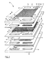
- the single fuel cell assembly 10 comprises a pair of spaced interconnect plates 12 and 14 with a single fuel cell 16 between them.
- the present invention is particularly applicable to a stack of a plurality of fuel cells, but will operate with a single fuel cell and is described accordingly for convenience.
- the fuel cell 16 is illustrated as of the type in which the anode 18 is the primary load bearing layer with a thin electrolyte layer 20 on one surface and a thin cathode layer 22 applied to the electrolyte layer 20.
- Such cells are known for intermediate temperature operation of a fuel cell assembly, at around 800 ⁇ C, but the fuel cell 16 could be replaced by, for example, a fuel cell as described in the aforementioned International patent applications.
- the solid oxide electrolyte layer 20 may comprise Y 2 O 3 -doped ZrO 2 (YSZ) having a thickness of about 20 microns laminated on a Ni/YSZ anode having a thickness greater than about 0.5mm, for example 0.8 to 1.0mm.
- the cathode layer 22 may comprise strontium doped lanthanum manganite (LSM) having a thickness of about 50 to 100 microns.
- the anode and cathode layers 18 and 22 are porous, and the cathode layer 22 is of reduced area compared to the anode and electrolyte layers 18 and 20, not extending to the periphery of the electrolyte 20, for sealing purposes.
- the interconnect plates 12 and 14 may be formed of any of the materials described in the aforementioned International patent applications, but are preferably formed of corrosion resistant stainless steel which has a degree of creep at the operating temperature allowing improved electrical contact and stress relief without optical grinding to provide smooth surfaces.
- a suitable material is described in our co-pending Australian patent application entitled "A Heat Resistant Steel”.
- the stainless steel interconnect plates may be suitably coated to enhance electrical contact.
- the cathode side 24 may have a coating of La-Sr-CrO 3 (LSC), while the anode side 26 may have a nickel coating.
- LSC La-Sr-CrO 3
- the interconnect plates 12 and 14 are shown ribbed on only the cathode side 24 to facilitate air flow across the cathode layer 22 of the fuel cell 16, and the channels 28 between the ribs 30 may have an alumina coating to minimise corrosion.
- fuel gas flow on the anode side 26 of the interconnect plates is directed by a compression member 32, as described hereinafter, but it could be facilitated by cooperating channels in the anode side 26 of the interconnect plates, or the fuel gas distribution across the anode side 18 of the fuel cell 16 may be performed substantially only by channels on the anode side 26 of the interconnect plates, for example as described in the aforementioned International patent applications.
- the interconnect plates 12 and 14 are spaced apart by an insulating spacer plate 34 having an opening 36 therethrough defining a chamber between the interconnect plates within which the fuel cell 16 is received.
- the spacer plate may be formed of, for example, alumina or a conducting material such as stainless steel with an insulating coating, for example of alumina.
- the insulating spacer plate 34 is of greater thickness than the fuel cell 16, and the compression member 32 is disposed between the interconnect plate 12 and the anode layer 18 of the fuel cell 16 within the chamber defined by the opening 36 of the spacer 34.
- the compression member 32 may be formed of for example nickel or nickel alloy and maintains electrical contact between the interconnect plate 12 and the anode layer 18 of the fuel cell.
- the compression member 32 applies pressure to the fuel cell 16 from the interconnect plate 12 to maintain the cathode layer 22 in electrical contact with the cathode side 24 of the interconnect plate 14.
- this pressure is limited by the spacer plate 34 so that it is independent of the number of fuel cell assemblies which may be above the assembly 10 in a stack. This greatly enhances use of the relatively weak fuel cell 16 compared to the fuel cells described in the aforementioned International patent applications.
- the compression member 32 comprises three sheets of superposed expanded nickel mesh.
- the outer sheets 38 and 40 are flat, but the inner sheet 42 is corrugated.
- Each of the sheets has a thickness of about quarter of a millimetre, and the overall thickness of the compression member 32 is 1.5 to 2mm, for example about 1.7mm.
- the corrugated nature of the inner sheet 42 facilitates fuel gas flow across the chamber defined by the opening 36, and the open mesh nature of the expanded sheets allows the distributed fuel gas to contact the anode layer 18 of the fuel cell.
- the corrugated inner sheet 42 also gives the member 32 a degree of compressibility through its thickness so as to provide the desired compressive force between the interconnect plate 12 and the fuel cell.
- the compressive force must be able to be maintained throughout use of the fuel cell, in order to maintain electrical contact between the fuel cell and both interconnect plates 12 and 14, and the inner sheet 42 is advantageously secured to one of the outer sheets 38 and 40, for example by spot welding, to increase the resistance to compression.
- the inner sheet 42 is spot welded to the outer sheet 38 and the outer sheet 40 alleviates any sliding contact between the inner sheet 42 as it is compressed and the anode layer 18 of the fuel cell.
- the outer sheet 38 may be omitted and the corrugated inner sheet 42 may be spot welded directly to the interconnect plate 12.
- the outer sheet 40 could also be omitted.
- the corrugated inner sheet 42 could be bonded to one of the outer sheets 38 and 40, as by spot welding, and the other outer sheet may be omitted. It is envisaged that a replacement of the nickel material of the compression member 32 by nickel alloy may improve the desirable characteristics of the compression member.
- the portion of the gasket 44 contacting the peripheral region 46 of the fuel cell could be separate from the portion of the gasket contacting the spacer plate 34.
- a thinner glass containing gasket 48 is disposed between the spacer plate 34 and the anode side 26 of the interconnect plate 12 to seal the anode side of the chamber.
- the gaskets 44 and 48 are conveniently formed of plural layers of glass containing material which is rigid under ambient conditions but which becomes viscous at the operating temperature of the fuel cell. This enables the gaskets 44 and 48, particularly the thicker gasket 44, to compress and thereby ensure the desired seal, with the compression in practice being such as to ensure the cathode layer 22 on the fuel cell is urged by the compression member 32 into contact with the cathode side 24 of the interconnect plate 14. As the gaskets 44 and 48 are compressed, the interconnect plates 12 and 14 move towards each other, but this movement is limited by the spacer plate 34 so that the degree of compression applied to the fuel cell by the compression member 32 is limited and is independent of the position of the fuel cell assembly 10 in a stack of fuel cells.
- the fuel cell assembly 10 is internally manifolded, that is manifolds for the oxygen-containing gas and fuel gas extend through the interconnect plates 12 and 14 and the spacer plate 34, as well as through the gaskets 44 and 48.
- this is not essential and the fuel cell assembly 10 could be externally manifolded.
- the oxygen-containing gas inlet and outlet manifolds 50 and 52 communicate with the distribution channels 28 in the interconnect plate by way of inlet and outlet passages 58 and 60 and distributors 62 and 64 defined by grooves in the interconnect plate.
- the inlet and outlet channels 58 and 60 are recessed on each side at 66 to receive a sealing shim (not shown), for example of stainless steel.
- the gasket 44 may extend over the sealing shim.
- the spacer plate 34 has fuel gas inlet and outlet passages 68 and 70 defined by respective grooves extending between the manifold passages 54 and 56 therethrough and the opening 36 defining the chamber for the fuel cell 16 and compression member 32.
- the present invention may be applied also to a fuel cell assembly incorporating a parallel array of, for example, four fuel cells.
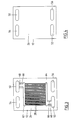
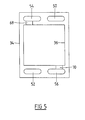
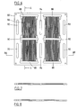
- One interconnect plate 80 and one spacer plate 82 are illustrated for this purpose in Figures 6 to 8 and Figures 9 and 10 respectively.
- the fuel cells are not shown, but they will be individual and may be identical to the fuel cell 16 described above.
- interconnect plate 80 and spacer plate 82 will be assembled in identical manner as has been described above with correspondingly shaped sealing gaskets above and below the spacer plate 82 extending around the four openings 84 in the spacer plate defining chambers within which respective assemblies of a fuel cell and a compression member such as the member 32 will be received.
- the interconnect plate 80 and spacer plate 82 are also internally manifolded, but in a different manner to the manifolding in the fuel assembly 10.
- a cross flow arrangement is used so that the compression member 32 would be rotated through 90" compared to its orientation in the fuel assembly 10 with the distribution channels defined by the corrugations of the inner sheet 42 extending perpendicularly to the air side distribution channels 86 in the interconnect plate 80.
- This arrangement allows the arrayed fuel cell assemblies to be paired for manifolding purposes.
- each array has a respective oxygen-containing gas inlet manifold passage 88 for each fuel cell, respective oxygen-containing gas outlet manifold passages 90 are common to paired fuel cells.
- each array has a respective fuel gas inlet manifold passage 92 for each fuel cell, but fuel gas outlet manifold passages 94 are common to respective pairs of the fuel cells.
- the manifold passages all extend at least substantially across the full width of the respective opening(s) 84. It will be appreciated that the respective gas flows may be reversed by swapping the inlet and outlet manifold passages.
- Example 1 only a single fuel cell was tested, but in Example 2 the fuel cell assembly comprised a six cell stack.
- the cell assemblies in the Examples were identical and comprised 50mm by 50mm fuel cells, each comprising a Ni/YSZ anode layer of greater than 0.5mm thickness having a 20 micron YSZ electrolyte layer laminated thereto with a 100 micron LSM cathode layer on the other side of the electrolyte.
- the compression member in each cell assembly comprise a corrugated expanded nickel mesh with flat sheets of nickel mesh on each side, one of which was spot welded to the corrugated mesh, to give a total thickness of about 1.7mm, each sheet having a thickness of about 230 microns.
- the interconnect members were corrosion resistant stainless steel having an LSC conducting layer on the ribs and an alumina coating in the distribution channels on the cathode side, and a nickel coating on the fuel side. The composition of the stainless steel was, in wt.
- the spacer plate in each fuel cell assembly was of alumina, with a thickness of 2mm, and the gaskets were of a glass-containing material which became viscous at the operating temperature of 800°C. The thicknesses of the gaskets were adjusted so as to be optimum for providing the desired sealing.
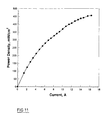
- the stack was heated in the test station to 800°C. Then the stack was tested with 4 % water in hydrogen as the fuel gas and air as the oxidant gas. The stack sealed well, with all six cells reaching the theoretical open circuit voltage of 1.084 V. The stack reached a peak power of 29 W at 10 A, as shown in Figure 12. The stack was then operated at 150 mA/cm 2 and 200 mA/cm 2 for a period of 250 hours before being shut down for analysis, and the results are shown in Figure 14. The stack sealed well over the complete test period. In-situ electrochemical tests indicated excellent contact between the cells and the interconnect plates, demonstrating the compression members were working well.
Claims (32)
- Brennstoffzellenanordnung (10), enthaltend eine ebene Brennstoffzelle (16), die eine Elektrolytschicht (20) mit einer Anodenschicht (18) auf einer Seite und einer Katodenschicht (22) auf der anderen Seite aufweist, wobei die Brennstoffzelle zwischen und in elektrischem Kontakt mit jeweiligen verbindungselementen (12, 14) angeordnet ist, wobei Kanaleinrichtungen (28) für Sauerstoff enthaltendes Gas zwischen der Katodenschicht und dem benachbarten Verbindungselement (14) gebildet sind und Brennstoffgas-Kanaleinrichtungen zwischen der Anodenschicht und dem benachbarten Verbindungselement (12) gebildet sind, dadurch gekennzeichnet, dass eine Kammer (36) mit größerer Höhe als die Dicke der Brennstoffzelle zwischen den Verbindungselementen definiert ist, innerhalb welcher die Brennstoffzelle aufgenommen ist, dass eine elektrisch leitfähige kompressible Einrichtung (32) ebenfalls innerhalb der Kammer in elektrischem Kontakt mit einer ersten Seite (18) der Brennstoffzelle und dem benachbarten Verbindungselement (12) angeordnet ist und die Brennstoffzelle zu dem benachbarten Verbindungselement (14) auf der zweiten Seite (22) davon drängt, um die Brennstoffzelle in elektrischem Kontakt mit beiden Verbindungselementen zu halten, und dass die Brennstoffzelle innerhalb der Kammer, abgesehen von der elektrisch leitfähigen kompressiblen Einrichtung, verschieblich aufgenommen ist.
- Brennstoffzellenanordnung nach Anspruch 1, enthaltend einen Stapel (10) aus einer Vielzahl von ebenen Brennstoffzellen (16), die jeweils eine Elektrolytschicht (20) mit einer Anodenschicht (18) auf einer Seite und einer Katodenschicht (22) auf der anderen Seite aufweisen, und eine Vielzahl von Verbindungselementen (12, 14), wobei jede Brennstoffzelle zwischen und in elektrischem Kontakt mit einem benachbarten Paar von Verbindungselementen angeordnet ist, wobei Kanaleinrichtungen (28) für Sauerstoff enthaltendes Gas zwischen der Katodenschicht jeder Brennstoffzelle und dem benachbarten Verbindungselement (12, 14) gebildet sind und Brennstoffgas-Kanaleinrichtungen zwischen der Anodenschicht jeder Brennstoffzelle und dem benachbarten Verbindungselement (12, 14) gebildet sind, dadurch gekennzeichnet, dass eine Kammer (36) mit größerer Höhe als die Dicke der jeweiligen Brennstoffzelle zwischen den benachbarten Verbindungselementen in jedem Paar gebildet ist, innerhalb welcher die Brennstoffzelle aufgenommen ist, dass eine elektrisch leitfähige kompressible Einrichtung (32) ebenfalls innerhalb der Kammer in elektrischem Kontakt mit einer ersten Seite (18) der Brennstoffzelle und dem benachbarten Verbindungselement (12) angeordnet ist und die Brennstoffzelle zu dem benachbarten Verbindungselement (14) auf der zweiten Seite (22) davon drängt, um die Brennstoffzelle in elektrischem Kontakt mit beiden Verbindungselementen zu halten, und dass jede Brennstoffzelle innerhalb der jeweiligen Kammer, abgesehen von der zugehörigen elektrisch leitfähigen kompressiblen Einrichtung, verschieblich aufgenommen ist.
- Brennstoffzellenanordnung nach Anspruch 1 oder Anspruch 2, dadurch gekennzeichnet, dass die elektrisch leitfähige kompressible Einrichtung (32) auf der Anodenseite der Brennstoffzelle angeordnet ist.
- Brennstoffzellenanordnung nach Anspruch 3, dadurch gekennzeichnet, dass die elektrisch leitfähige kompressible Einrichtung (32) aus einem Material gebildet ist, das ausgewählt ist aus einem Metall aus den Gruppen 8-11 des Periodensystems, einer Legierung eines oder mehrerer dieser Metalle und einem solchen Metall, das Oxid-Dispersions-gefestigt wurde.
- Brennstoffzellenanordnung nach Anspruch 4, dadurch gekennzeichnet, dass das Metall Nickel ist.
- Brennstoffzellenanordnung nach einem der vorstehenden Ansprüche, dadurch gekennzeichnet, dass die elektrisch leitfähige kompressible Einrichtung (32) ausgewählt ist aus einer Struktur, die bei Betriebstemperatur eine gewisse Elastizität behält, und einem Verbundstoff aus einem porösen spröden Material und einem Metall.
- Brennstoffzellenanordnung nach Anspruch 6, dadurch gekennzeichnet, dass die elektrisch leitfähige kompressible Einrichtung (32) ein gewelltes Blech (42) aus Metall oder metallischem Material aufweist.
- Brennstoffzellenanordnung nach Anspruch 7, dadurch gekennzeichnet, dass das gewellte Blech (42) ein Streckmetallblech ist.
- Brennstoffzellenanordnung nach Anspruch 7 oder 8, dadurch gekennzeichnet, dass ein flaches Blech (40) aus Metall oder metallischem Material zwischen dem gewellten Blech (42) und der Brennstoffzelle (16) angeordnet ist.
- Brennstoffzellenanordnung nach Anspruch 9, dadurch gekennzeichnet, dass das flache Blech (40) ein Streckmetallblech ist.
- Brennstoffzellenanordnung nach einem der Ansprüche 7 bis 10, dadurch gekennzeichnet, dass ein flaches Blech (38) aus Metall oder metallischem Material zwischen dem gewellten Blech (42) und dem benachbarten Verbindungselement (12) angeordnet ist.
- Brennstoffzellenanordnung nach Anspruch 11, dadurch gekennzeichnet, dass das zwischen dem gewellten Blech (42) und dem benachbarten Verbindungselement (12) angeordnete flache Blech (38) ein Streckmetallblech ist.
- Brennstoffzellenanordnung nach Anspruch 11 oder 12, dadurch gekennzeichnet, dass das zwischen dem gewellten Blech (42) und dem benachbarten verbindungselement (12) angeordnete flache Blech (38) mit dem gewellten Blech (42) verbunden ist.
- Brennstoffzellenanordnung nach einem der Ansprüche 7 bis 13, dadurch gekennzeichnet, dass die elektrisch leitfähige kompressible Einrichtung mit dem benachbarten Verbindungselement (12) verbunden ist.
- Brennstoffzellenanordnung nach Anspruch 14, dadurch gekennzeichnet, dass die elektrisch leitfähige kompressible Einrichtung (32) mit dem benachbarten Verbindungselement (12) durch Punktschweißung verbunden ist.
- Brennstoffzellenanordnung nach einem der Ansprüche 7 bis 15, dadurch gekennzeichnet, dass die elektrisch leitfähige kompressible Einrichtung (32) die Gas-Kanaleinrichtungen zwischen der ersten Seite (18) der Brennstoffzelle (16) und dem benachbarten Verbindungselement (12) bildet und mit einer flachen Seite des benachbarten Verbindungselements in Kontakt steht.
- Brennstoffzellenanordnung nach einem der vorstehenden Ansprüche, dadurch gekennzeichnet, dass die elektrisch leitfähige kompressible Einrichtung (32) an einer oberen Seite der Brennstoffzelle (16) angeordnet ist.
- Brennstoffzellenanordnung nach einem der vorstehenden Ansprüche, dadurch gekennzeichnet, dass eine Dichtung (44) um einen Umfangsabschnitt (46) der Brennstoffzelle (16) zwischen ihrer zweiten Seite (22) und dem benachbarten Verbindungselement (14) vorgesehen ist, um das Sauerstoff enthaltende Gas und das Brennstoffgas in der Kammer gegeneinander abzudichten.
- Brennstoffzellenanordnung nach Anspruch 18, dadurch gekennzeichnet, dass die Dichtung (44) in Kontakt mit der Elektrolytschicht (20) ist.
- Brennstoffzellenanordnung nach Anspruch 18 oder 19, dadurch gekennzeichnet, dass die Dichtung (44) beim Gebrauch komprimierbar ist.
- Brennstoffzellenanordnung nach Anspruch 20, dadurch gekennzeichnet, dass die Dichtung (44) bei Raumtemperatur fest ist und bei Betriebstemperatur der Zelle viskos ist.
- Brennstoffzellenanordnung nach Anspruch 20 oder 21, dadurch gekennzeichnet, dass die Dichtung (44) in dem Ausmaß komprimierbar ist, dass die Elektrodenschicht (22) auf der zweiten Seite der Brennstoffzelle (16) anfänglich von dem benachbarten Verbindungselement (14) beabstandet ist und unter der Betriebstemperatur an dem benachbarten Verbindungselement anliegt und elektrischen Kontakt mit diesem herstellt.
- Brennstoffzellenanordnung nach einem der Ansprüche 20 bis 22, dadurch gekennzeichnet, dass die Dichtung (44) in Form einer Glas enthaltenden Dichtung vorliegt.
- Brennstoffzellenanordnung nach Anspruch 23, dadurch gekennzeichnet, dass die Dichtung (44) mehrere Schichten von Glas enthaltendem Material enthält.
- Brennstoffzellenanordnung nach einem der Ansprüche 18 bis 24, dadurch gekennzeichnet, dass die Dichtung (44) um die Kammer verläuft, um die Kammer zumindest teilweise gegen die äußere Umgebung abzudichten.
- Brennstoffzellenanordnung nach einem der Ansprüche 18 bis 24, dadurch gekennzeichnet, dass ein separates Dichtungselement um die Kammer verläuft, um die Kammer zumindest teilweise gegen die äußere Umgebung abzudichten.
- Brennstoffzellenanordnung nach Anspruch 26, dadurch gekennzeichnet, dass das Dichtungselement die gleichen Eigenschaften wie die Dichtung (44) hat.
- Brennstoffzellenanordnung nach einem der vorstehenden Ansprüche, dadurch gekennzeichnet, dass ein isolierender Abstandhalter (34) um die Brennstoffzelle (16) und die elektrisch leitfähige kompressible Einrichtung (33) verläuft, um die Kammer zumindest teilweise zu bilden.
- Brennstoffzellenanordnung nach Anspruch 28, dadurch gekennzeichnet, dass ein Dichtungselement (48) zwischen dem isolierenden Abstandhalter (34) und dem der ersten Seite (18) der Brennstoffzelle (16) benachbarten Verbindungselement (12) angeordnet ist.
- Brennstoffzellenanordnung nach einem der vorstehenden Ansprüche, dadurch gekennzeichnet, dass sie mit internen Verteilungsleitungen versehen ist.
- Brennstoffzellenanordnung nach einem der vorstehenden Ansprüche, dadurch gekennzeichnet, dass die oder jede Brennstoffzelle (16) eine einer Gruppierung in einer jeweiligen Schicht von mehreren ebenen Brennstoffzellen in der Anordnung ist, wobei jede in einer wie in Anspruch 1 definierten Kammer angeordnet ist.
- Brennstoffzellenanordnung nach Anspruch 31, dadurch gekennzeichnet, dass die einer gemeinsamen Seite aller oder mehr als einer der Brennstoffzellen in jeder Gruppierung benachbarten Verbindungselemente als eine einzelne Platte (80) gebildet sind.
Applications Claiming Priority (3)
| Application Number | Priority Date | Filing Date | Title |
|---|---|---|---|
| AUPO7249A AUPO724997A0 (en) | 1997-06-10 | 1997-06-10 | A fuel cell assembly |
| AUPO724997 | 1997-06-10 | ||
| PCT/AU1998/000437 WO1998057384A1 (en) | 1997-06-10 | 1998-06-10 | A fuel cell assembly |
Publications (3)
| Publication Number | Publication Date |
|---|---|
| EP0988655A1 EP0988655A1 (de) | 2000-03-29 |
| EP0988655A4 EP0988655A4 (de) | 2004-04-14 |
| EP0988655B1 true EP0988655B1 (de) | 2007-05-30 |
Family
ID=3801540
Family Applications (1)
| Application Number | Title | Priority Date | Filing Date |
|---|---|---|---|
| EP98923931A Expired - Lifetime EP0988655B1 (de) | 1997-06-10 | 1998-06-10 | Eine brennstofzellenanordnung |
Country Status (7)
| Country | Link |
|---|---|
| US (1) | US6492053B1 (de) |
| EP (1) | EP0988655B1 (de) |
| JP (1) | JP2002503381A (de) |
| AU (1) | AUPO724997A0 (de) |
| DE (1) | DE69837848T2 (de) |
| NZ (1) | NZ501642A (de) |
| WO (1) | WO1998057384A1 (de) |
Cited By (1)
| Publication number | Priority date | Publication date | Assignee | Title |
|---|---|---|---|---|
| EP2953197A4 (de) * | 2013-01-31 | 2016-10-19 | Ngk Spark Plug Co | Brennstoffzelle und brennstoffzellenstapel |
Families Citing this family (100)
| Publication number | Priority date | Publication date | Assignee | Title |
|---|---|---|---|---|
| US6265095B1 (en) * | 1999-03-01 | 2001-07-24 | Sofco | Interconnect for solid oxide fuel cells |
| US6106967A (en) * | 1999-06-14 | 2000-08-22 | Gas Research Institute | Planar solid oxide fuel cell stack with metallic foil interconnect |
| US7354675B2 (en) | 1999-10-07 | 2008-04-08 | Proton Energy Systems, Inc. | Apparatus and method for maintaining compression of the active area in an electrochemical cell |
| AUPQ492199A0 (en) * | 1999-12-30 | 2000-02-03 | Ceramic Fuel Cells Limited | Laminated structure and method of forming same |
| AU2001293140A1 (en) | 2000-09-27 | 2002-04-08 | Proton Energy Systems, Inc. | Apparatus and method for maintaining compression of the active area in an electrochemical cell |
| US6869720B2 (en) | 2000-09-27 | 2005-03-22 | Proton Energy Systems, Inc. | Method and apparatus for maintaining compression of the active area in an electrochemical cell |
| WO2002027813A2 (en) * | 2000-09-27 | 2002-04-04 | Proton Energy Systems, Inc. | Apparatus and method for maintaining compression of the active area in an electrochemical cell |
| AU2001293139A1 (en) | 2000-09-27 | 2002-04-08 | Proton Energy Systems, Inc. | Method and apparatus for maintaining compression of the active area in an electrochemical cell |
| US6824910B2 (en) | 2001-01-24 | 2004-11-30 | The Regents Of The University Of California | Co-flow planar SOFC fuel cell stack |
| JP4615143B2 (ja) | 2001-05-14 | 2011-01-19 | 東京瓦斯株式会社 | 平板形固体酸化物燃料電池及びそのための合金製セパレータ |
| US7122266B2 (en) | 2001-09-13 | 2006-10-17 | Ngk Insulators, Ltd. | Holding member for holding an electrochemical cell, a holding substrate for the same, an electrochemical system and a connecting member for electrochemical cells |
| US7008716B2 (en) * | 2001-10-01 | 2006-03-07 | Delphi Technologies, Inc. | Gasket material for a fuel cell |
| US6821667B2 (en) * | 2001-10-01 | 2004-11-23 | Delphi Technologies, Inc. | Fuel cell stack having foil interconnects and laminated spacers |
| US20060166053A1 (en) * | 2001-11-21 | 2006-07-27 | Badding Michael E | Solid oxide fuel cell assembly with replaceable stack and packet modules |
| US7067208B2 (en) * | 2002-02-20 | 2006-06-27 | Ion America Corporation | Load matched power generation system including a solid oxide fuel cell and a heat pump and an optional turbine |
| KR100675613B1 (ko) * | 2002-06-28 | 2007-01-30 | 혼다 기켄 고교 가부시키가이샤 | 연료전지 및 연료전지스택 |
| NL1020985C2 (nl) * | 2002-07-03 | 2004-01-06 | Stichting Energie | Anodegedragen brandstofcel. |
| US7163761B2 (en) | 2002-11-14 | 2007-01-16 | 3M Innovative Properties Company | Fuel cell stack |
| US20050208367A1 (en) * | 2002-11-22 | 2005-09-22 | Bayerische Motoren Werke Ag | Carrier substrate for an electrode layer of a fuel cell and method for the production thereof |
| US20040200187A1 (en) * | 2002-11-27 | 2004-10-14 | Warrier Sunil G. | Compliant, strain tolerant interconnects for solid oxide fuel cell stack |
| US20040131915A1 (en) * | 2002-11-28 | 2004-07-08 | Scott Sherman | Solid oxide fuel cell stack |
| US7329471B2 (en) * | 2002-12-10 | 2008-02-12 | General Electric Company | Methods and apparatus for assembling solid oxide fuel cells |
| DE10302122A1 (de) * | 2003-01-21 | 2004-07-29 | Elringklinger Ag | Dichtungsaufbau für eine Brennstoffzelle bzw. einen Elektrolyseur sowie Verfahren zu dessen Herstellung und Brennstoffzelle bzw. Elektrolyseur aufweisend den Dichtungsaufbau |
| US20040185321A1 (en) * | 2003-02-14 | 2004-09-23 | David Sutherland | Sofc with floating current collectors |
| US7553579B2 (en) * | 2003-04-04 | 2009-06-30 | Versa Power Systems Ltd. | Solid oxide fuel cell stack with floating cells |
| DE10342691A1 (de) * | 2003-09-08 | 2005-04-07 | Fraunhofer-Gesellschaft zur Förderung der angewandten Forschung e.V. | Stapelbare Hochtemperaturbrennstoffzelle |
| US7358005B2 (en) * | 2003-09-18 | 2008-04-15 | General Electric Company | Methods and apparatus for isolating solid oxide fuel cells |
| DE10358458B4 (de) * | 2003-12-13 | 2010-03-18 | Elringklinger Ag | Brennstoffzellenstapel und Verfahren zum Herstellen eines Brennstoffzellenstapels |
| US20050136312A1 (en) * | 2003-12-22 | 2005-06-23 | General Electric Company | Compliant fuel cell system |
| JP4643923B2 (ja) * | 2004-04-05 | 2011-03-02 | 本田技研工業株式会社 | 燃料電池及び燃料電池スタック |
| US7632595B1 (en) * | 2004-04-05 | 2009-12-15 | General Electric Company | Compliant fuel cell system |
| US20050227134A1 (en) * | 2004-04-13 | 2005-10-13 | Ion American Corporation | Offset interconnect for a solid oxide fuel cell and method of making same |
| DK1790025T3 (da) * | 2004-08-30 | 2010-03-15 | Fraunhofer Ges Forschung | Stabelbar højtemperaturbrændselscelle |
| US7803493B2 (en) * | 2004-09-29 | 2010-09-28 | General Electric Company | Fuel cell system with separating structure bonded to electrolyte |
| US20060180247A1 (en) * | 2005-02-15 | 2006-08-17 | United States Of America As Represented By The Secretary Of The Navy | Process for preparing chromium conversion coatings for iron and iron alloys |
| US20070037031A1 (en) * | 2005-07-13 | 2007-02-15 | Ion America Corporation | Cermet and ceramic interconnects for a solid oxide fuel cell |
| JP2007026812A (ja) * | 2005-07-14 | 2007-02-01 | Toyota Auto Body Co Ltd | ガス流路形成部材の製造方法、燃料電池用メタルセパレータのガス流路形成部材および貫通孔形成装置。 |
| US9985295B2 (en) * | 2005-09-26 | 2018-05-29 | General Electric Company | Solid oxide fuel cell structures, and related compositions and processes |
| US20070072070A1 (en) * | 2005-09-26 | 2007-03-29 | General Electric Company | Substrates for deposited electrochemical cell structures and methods of making the same |
| US20070072046A1 (en) * | 2005-09-26 | 2007-03-29 | General Electric Company | Electrochemcial cell structures and methods of making the same |
| US8691474B2 (en) * | 2006-04-03 | 2014-04-08 | Bloom Energy Corporation | Fuel cell stack components and materials |
| US7951509B2 (en) * | 2006-04-03 | 2011-05-31 | Bloom Energy Corporation | Compliant cathode contact materials |
| DE102006024039A1 (de) * | 2006-05-23 | 2007-11-29 | Forschungszentrum Jülich GmbH | Interkonnektor für einen Brennstoffzellenstapel und Verfahren zur Herstellung |
| JP4949737B2 (ja) * | 2006-05-29 | 2012-06-13 | 日本電信電話株式会社 | 固体酸化物形燃料電池セルスタックおよび固体酸化物形燃料電池 |
| EP2041822B1 (de) * | 2006-07-11 | 2016-11-02 | Intelligent Energy Ltd | Verbesserte brennstoffzellenanordnung |
| DE102006058335A1 (de) * | 2006-12-11 | 2008-06-12 | Staxera Gmbh | Brennstoffzellenstapel und Dichtung für einen Brennstoffzellenstapel sowie deren Herstellungsverfahren |
| CA2684377A1 (en) * | 2007-04-02 | 2008-10-09 | Staxera Gmbh | Contact arrangement and method for assembling a fuel cell stack from at least one contact arrangement |
| US7931997B2 (en) * | 2008-03-12 | 2011-04-26 | Bloom Energy Corporation | Multi-material high temperature fuel cell seals |
| CN101999184B (zh) * | 2008-03-24 | 2016-06-22 | 照明能源有限公司 | 模块化电池、这种电池用的互连器和与模块化电池有关的方法 |
| CN101290746A (zh) * | 2008-06-18 | 2008-10-22 | 北京工业大学 | 电子纸屏幕的图像更新方法 |
| US8986905B2 (en) | 2008-11-11 | 2015-03-24 | Bloom Energy Corporation | Fuel cell interconnect |
| US8623569B2 (en) * | 2008-12-09 | 2014-01-07 | Bloom Energy Corporation | Fuel cell seals |
| US8652697B2 (en) | 2009-02-25 | 2014-02-18 | Bloom Energy Corporation | Controlling a fuel cell system based on fuel cell impedance characteristic |
| WO2010108057A2 (en) * | 2009-03-20 | 2010-09-23 | Bloom Energy Corporation | Crack free sofc electrolyte |
| US8173294B2 (en) | 2009-04-28 | 2012-05-08 | Lightening Energy | High voltage modular battery with electrically-insulated cell module and interconnector peripheries |
| US8343642B2 (en) | 2009-12-31 | 2013-01-01 | Lightening Energy | High voltage modular battery with compression bladder |
| US8822064B2 (en) * | 2009-12-31 | 2014-09-02 | Lightening Energy | Modular battery with polymeric compression sealing |
| US20110177383A1 (en) * | 2010-01-19 | 2011-07-21 | Lightening Energy | Battery cell module for modular battery with interleaving separator |
| US20110200867A1 (en) * | 2010-02-16 | 2011-08-18 | Lightening Energy | Modular battery with battery cell having bimetallic end plates |
| US8968956B2 (en) | 2010-09-20 | 2015-03-03 | Nextech Materials, Ltd | Fuel cell repeat unit and fuel cell stack |
| JP2012119209A (ja) * | 2010-12-02 | 2012-06-21 | Nippon Telegr & Teleph Corp <Ntt> | 固体酸化物形燃料電池 |
| US20120214081A1 (en) * | 2011-02-21 | 2012-08-23 | Atomic Energy Council-Institute Of Nuclear Energy Research | Laminate for Use in a Fuel Cell and Method for Making the Same |
| US8350526B2 (en) | 2011-07-25 | 2013-01-08 | Lightening Energy | Station for rapidly charging an electric vehicle battery |
| US8174235B2 (en) | 2011-07-25 | 2012-05-08 | Lightening Energy | System and method for recharging electric vehicle batteries |
| US9786961B2 (en) | 2011-07-25 | 2017-10-10 | Lightening Energy | Rapid charging electric vehicle and method and apparatus for rapid charging |
| TWI552417B (zh) | 2011-11-17 | 2016-10-01 | 博隆能源股份有限公司 | 對氧化鋯為主之電解質提供抗腐蝕性之多層塗層 |
| WO2013074918A1 (en) | 2011-11-18 | 2013-05-23 | Bloom Energy Corporation | Fuel cell interconnects and methods of fabrication |
| US10110056B2 (en) | 2012-02-16 | 2018-10-23 | Lightening Energy | Energy banking system and method using rapidly rechargeable batteries |
| US9452475B2 (en) | 2012-03-01 | 2016-09-27 | Bloom Energy Corporation | Coatings for SOFC metallic interconnects |
| JP5872951B2 (ja) * | 2012-04-21 | 2016-03-01 | 日本特殊陶業株式会社 | 燃料電池 |
| EP2675006A1 (de) | 2012-06-11 | 2013-12-18 | HTceramix S.A. | Gasverteilungselement mit Stützschicht |
| EP2675007A1 (de) | 2012-06-11 | 2013-12-18 | HTceramix S.A. | Gasströmungsteilungselement |
| EP2675005A1 (de) | 2012-06-11 | 2013-12-18 | HTceramix S.A. | Gasverteilungselement für eine Brennstoffzelle |
| US9847520B1 (en) | 2012-07-19 | 2017-12-19 | Bloom Energy Corporation | Thermal processing of interconnects |
| US11217797B2 (en) | 2012-08-29 | 2022-01-04 | Bloom Energy Corporation | Interconnect for fuel cell stack |
| KR20150067293A (ko) * | 2012-10-09 | 2015-06-17 | 누베라 퓨엘 셀스, 인크. | 전도―냉각형 전기화학 셀들에서 이용하기 위한 바이폴라 플레이트들의 설계 |
| US9478812B1 (en) | 2012-10-17 | 2016-10-25 | Bloom Energy Corporation | Interconnect for fuel cell stack |
| US9368810B2 (en) | 2012-11-06 | 2016-06-14 | Bloom Energy Corporation | Interconnect and end plate design for fuel cell stack |
| CN105143518B (zh) * | 2013-05-02 | 2018-11-20 | 托普索公司 | 用于soec单元的气体入口 |
| WO2014177213A1 (en) | 2013-05-02 | 2014-11-06 | Topsoe Energy Conversion & Storage A/S | Gas inlet for soc unit |
| US8968509B2 (en) | 2013-05-09 | 2015-03-03 | Bloom Energy Corporation | Methods and devices for printing seals for fuel cell stacks |
| US9583771B2 (en) | 2013-05-16 | 2017-02-28 | Bloom Energy Coporation | Corrosion resistant barrier layer for a solid oxide fuel cell stack and method of making thereof |
| DE102013213399A1 (de) * | 2013-07-09 | 2015-01-15 | Elringklinger Ag | Elektrochemischer Wandler |
| EP3053211A4 (de) | 2013-10-01 | 2017-07-05 | Bloom Energy Corporation | Vorgeformte pulverzufuhrvorrichtung für eine pulverpressmaschine |
| US10096844B2 (en) * | 2013-10-03 | 2018-10-09 | Hamilton Sundstrand Corporation | Manifold for plural fuel cell stacks |
| US9468736B2 (en) | 2013-11-27 | 2016-10-18 | Bloom Energy Corporation | Fuel cell interconnect with reduced voltage degradation over time |
| EP3084870B1 (de) | 2014-01-09 | 2019-04-10 | Chaozhou Three-Circle (Group) Co., Ltd. | Elektrochemische energieumwandlungsvorrichtungen und zellen sowie positive elektrodenseitige materialien dafür |
| US10079393B1 (en) | 2014-01-09 | 2018-09-18 | Bloom Energy Corporation | Method of fabricating an interconnect for a fuel cell stack |
| TWI663771B (zh) | 2014-02-12 | 2019-06-21 | 美商博隆能源股份有限公司 | 多個燃料電池和電力電子供給負載並聯以允許整合電化學阻抗頻譜(eis)之燃料電池系統之結構及方法 |
| US9461319B2 (en) | 2014-02-21 | 2016-10-04 | Bloom Energy Corporation | Electrochemical impedance spectroscopy (EIS) analyzer and method of using thereof |
| WO2015130644A1 (en) | 2014-02-25 | 2015-09-03 | Bloom Energy Corporation | Composition and processing of metallic interconnects for sofc stacks |
| US9923211B2 (en) * | 2014-04-24 | 2018-03-20 | Bloom Energy Corporation | Fuel cell interconnect with reduced voltage degradation over time |
| US10573910B2 (en) | 2015-09-14 | 2020-02-25 | Bloom Energy Corporation | Electrochemical impedance spectroscopy (“EIS”) analyzer and method of using thereof |
| US10581106B2 (en) * | 2016-09-30 | 2020-03-03 | Cummins Enterprise Llc | Interconnect for an internally-manifolded solid oxide fuel cell stack; and related methods and power systems |
| JP6772861B2 (ja) * | 2017-01-30 | 2020-10-21 | 株式会社デンソー | 燃料電池セルスタック |
| US10763533B1 (en) | 2017-03-30 | 2020-09-01 | Bloom Energy Corporation | Solid oxide fuel cell interconnect having a magnesium containing corrosion barrier layer and method of making thereof |
| JP2021026924A (ja) * | 2019-08-07 | 2021-02-22 | マグネクス株式会社 | 金属製凹凸メッシュからなる集電体 |
| ES2934062T3 (es) | 2020-02-17 | 2023-02-16 | Topsoe As | Apilamiento de pilas de óxido sólido que comprende una interconexión y un separador integrados |
| KR20240005802A (ko) | 2021-05-03 | 2024-01-12 | 토프쉐 에이/에스 | 통합된 인터커넥트, 스페이서 및 매니폴드를 포함하는 고체 산화물 전지 스택 |
| CN117651788A (zh) | 2021-07-07 | 2024-03-05 | 托普索公司 | 包括集成的互连件、间隔件和用于接触使能层的固定部的soc堆 |
Family Cites Families (15)
| Publication number | Priority date | Publication date | Assignee | Title |
|---|---|---|---|---|
| DE2729640C3 (de) * | 1977-06-30 | 1980-07-24 | Siemens Ag, 1000 Berlin Und 8000 Muenchen | Batterie aus einer Mehrzahl elektrochemischer Zellen |
| US4702973A (en) * | 1986-08-25 | 1987-10-27 | Institute Of Gas Technology | Dual compartment anode structure |
| US4874678A (en) * | 1987-12-10 | 1989-10-17 | Westinghouse Electric Corp. | Elongated solid electrolyte cell configurations and flexible connections therefor |
| JPH01276565A (ja) * | 1988-04-27 | 1989-11-07 | Mitsubishi Electric Corp | 溶融炭酸塩型燃料電池 |
| US4983472A (en) | 1989-11-24 | 1991-01-08 | International Fuel Cells Corporation | Fuel cell current collector |
| AU637203B2 (en) * | 1990-03-13 | 1993-05-20 | Mitsubishi Jukogyo Kabushiki Kaisha | Power generation system with flat fuel cells of solid electrolyte |
| US4997727A (en) * | 1990-05-14 | 1991-03-05 | Asea Brown Boveri Ag | Stack of flat, plane high-temperature fuel cells assembled into a stack |
| US5338623A (en) * | 1992-02-28 | 1994-08-16 | Ceramatec, Inc. | Series tubular design for solid electrolyte oxygen pump |
| JPH05315004A (ja) * | 1992-05-08 | 1993-11-26 | Osaka Gas Co Ltd | 固体電解質型燃料電池 |
| US5366823A (en) * | 1992-12-17 | 1994-11-22 | United Technologies Corporation | Metal compression pad |
| US5273837A (en) * | 1992-12-23 | 1993-12-28 | Corning Incorporated | Solid electrolyte fuel cells |
| US5532073A (en) * | 1993-11-29 | 1996-07-02 | Kabushiki Kaisha Toshiba | Fuel cell |
| JPH08222245A (ja) * | 1994-12-13 | 1996-08-30 | Mitsubishi Heavy Ind Ltd | 平板型固体電解質燃料電池 |
| AUPN173595A0 (en) | 1995-03-15 | 1995-04-06 | Ceramic Fuel Cells Limited | Fuel cell interconnect device |
| US5549983A (en) * | 1996-01-22 | 1996-08-27 | Alliedsignal Inc. | Coflow planar fuel cell stack construction for solid electrolytes |
-
1997
- 1997-06-10 AU AUPO7249A patent/AUPO724997A0/en not_active Abandoned
-
1998
- 1998-06-10 JP JP50113999A patent/JP2002503381A/ja not_active Ceased
- 1998-06-10 EP EP98923931A patent/EP0988655B1/de not_active Expired - Lifetime
- 1998-06-10 DE DE69837848T patent/DE69837848T2/de not_active Expired - Lifetime
- 1998-06-10 NZ NZ501642A patent/NZ501642A/en unknown
- 1998-06-10 WO PCT/AU1998/000437 patent/WO1998057384A1/en active IP Right Grant
- 1998-06-10 US US09/445,735 patent/US6492053B1/en not_active Expired - Lifetime
Cited By (1)
| Publication number | Priority date | Publication date | Assignee | Title |
|---|---|---|---|---|
| EP2953197A4 (de) * | 2013-01-31 | 2016-10-19 | Ngk Spark Plug Co | Brennstoffzelle und brennstoffzellenstapel |
Also Published As
| Publication number | Publication date |
|---|---|
| DE69837848T2 (de) | 2008-01-31 |
| EP0988655A1 (de) | 2000-03-29 |
| WO1998057384A1 (en) | 1998-12-17 |
| DE69837848D1 (de) | 2007-07-12 |
| NZ501642A (en) | 2001-06-29 |
| US6492053B1 (en) | 2002-12-10 |
| AUPO724997A0 (en) | 1997-07-03 |
| EP0988655A4 (de) | 2004-04-14 |
| JP2002503381A (ja) | 2002-01-29 |
Similar Documents
| Publication | Publication Date | Title |
|---|---|---|
| EP0988655B1 (de) | Eine brennstofzellenanordnung | |
| EP1230706B1 (de) | Radialer plattenförmiger brennstoffzellenstapel mit festen elektrolyten | |
| US5460897A (en) | Solid oxide fuel cell stacking assembly | |
| US6255012B1 (en) | Pleated metal bipolar assembly | |
| US7449261B2 (en) | Holding member for holding an electrochemical cell, a holding substrate for the same, an electrochemical system and a connecting member for electrochemical cells | |
| US20040200187A1 (en) | Compliant, strain tolerant interconnects for solid oxide fuel cell stack | |
| US20050136312A1 (en) | Compliant fuel cell system | |
| CA2467772A1 (en) | Solid oxide fuel cell stack and packet designs | |
| US6821667B2 (en) | Fuel cell stack having foil interconnects and laminated spacers | |
| AU2004239806A1 (en) | Solid oxide fuel cell stack with floating cells | |
| KR100413397B1 (ko) | 고분자전해질형 연료전지와 그 사용방법 | |
| JP6893126B2 (ja) | 電気化学反応セルスタック | |
| JP6756549B2 (ja) | 電気化学反応単位および電気化学反応セルスタック | |
| JPH1116585A (ja) | 平板型固体電解質燃料電池及びその積層方法 | |
| US20050255363A1 (en) | Contact element for a fuel cell stack | |
| AU735079B2 (en) | A fuel cell assembly | |
| JP6777669B2 (ja) | 電気化学反応セルスタックの運転方法および電気化学反応システム | |
| JP3487606B2 (ja) | 固体電解質型燃料電池式発電炉 | |
| JPH10247509A (ja) | 円筒形セルタイプ固体電解質型燃料電池 |
Legal Events
| Date | Code | Title | Description |
|---|---|---|---|
| PUAI | Public reference made under article 153(3) epc to a published international application that has entered the european phase |
Free format text: ORIGINAL CODE: 0009012 |
|
| 17P | Request for examination filed |
Effective date: 19991221 |
|
| AK | Designated contracting states |
Kind code of ref document: A1 Designated state(s): DE FR GB IT NL |
|
| A4 | Supplementary search report drawn up and despatched |
Effective date: 20040227 |
|
| RIC1 | Information provided on ipc code assigned before grant |
Ipc: 7H 01M 8/02 B Ipc: 7H 01M 8/24 A |
|
| 17Q | First examination report despatched |
Effective date: 20040915 |
|
| GRAP | Despatch of communication of intention to grant a patent |
Free format text: ORIGINAL CODE: EPIDOSNIGR1 |
|
| GRAS | Grant fee paid |
Free format text: ORIGINAL CODE: EPIDOSNIGR3 |
|
| GRAA | (expected) grant |
Free format text: ORIGINAL CODE: 0009210 |
|
| AK | Designated contracting states |
Kind code of ref document: B1 Designated state(s): DE FR GB IT NL |
|
| REG | Reference to a national code |
Ref country code: GB Ref legal event code: FG4D |
|
| REF | Corresponds to: |
Ref document number: 69837848 Country of ref document: DE Date of ref document: 20070712 Kind code of ref document: P |
|
| ET | Fr: translation filed | ||
| NLV1 | Nl: lapsed or annulled due to failure to fulfill the requirements of art. 29p and 29m of the patents act | ||
| PG25 | Lapsed in a contracting state [announced via postgrant information from national office to epo] |
Ref country code: NL Free format text: LAPSE BECAUSE OF FAILURE TO SUBMIT A TRANSLATION OF THE DESCRIPTION OR TO PAY THE FEE WITHIN THE PRESCRIBED TIME-LIMIT Effective date: 20070530 |
|
| PLBE | No opposition filed within time limit |
Free format text: ORIGINAL CODE: 0009261 |
|
| STAA | Information on the status of an ep patent application or granted ep patent |
Free format text: STATUS: NO OPPOSITION FILED WITHIN TIME LIMIT |
|
| 26N | No opposition filed |
Effective date: 20080303 |
|
| PGFP | Annual fee paid to national office [announced via postgrant information from national office to epo] |
Ref country code: FR Payment date: 20100706 Year of fee payment: 13 |
|
| PGFP | Annual fee paid to national office [announced via postgrant information from national office to epo] |
Ref country code: IT Payment date: 20100625 Year of fee payment: 13 |
|
| PG25 | Lapsed in a contracting state [announced via postgrant information from national office to epo] |
Ref country code: IT Free format text: LAPSE BECAUSE OF NON-PAYMENT OF DUE FEES Effective date: 20110610 |
|
| REG | Reference to a national code |
Ref country code: FR Ref legal event code: ST Effective date: 20120229 |
|
| PG25 | Lapsed in a contracting state [announced via postgrant information from national office to epo] |
Ref country code: FR Free format text: LAPSE BECAUSE OF NON-PAYMENT OF DUE FEES Effective date: 20110630 |
|
| REG | Reference to a national code |
Ref country code: GB Ref legal event code: 732E Free format text: REGISTERED BETWEEN 20151112 AND 20151118 |
|
| REG | Reference to a national code |
Ref country code: DE Ref legal event code: R082 Ref document number: 69837848 Country of ref document: DE Representative=s name: DENNEMEYER & ASSOCIATES S.A., DE Ref country code: DE Ref legal event code: R081 Ref document number: 69837848 Country of ref document: DE Owner name: CNPC XING DE ENERGY SHARE LIMITED, HK Free format text: FORMER OWNER: CERAMIC FUEL CELLS LTD., NOBLE PARK, AU |
|
| PGFP | Annual fee paid to national office [announced via postgrant information from national office to epo] |
Ref country code: GB Payment date: 20160621 Year of fee payment: 19 Ref country code: DE Payment date: 20160621 Year of fee payment: 19 |
|
| REG | Reference to a national code |
Ref country code: GB Ref legal event code: 732E Free format text: REGISTERED BETWEEN 20161006 AND 20161012 |
|
| REG | Reference to a national code |
Ref country code: DE Ref legal event code: R119 Ref document number: 69837848 Country of ref document: DE |
|
| GBPC | Gb: european patent ceased through non-payment of renewal fee |
Effective date: 20170610 |
|
| PG25 | Lapsed in a contracting state [announced via postgrant information from national office to epo] |
Ref country code: DE Free format text: LAPSE BECAUSE OF NON-PAYMENT OF DUE FEES Effective date: 20180103 Ref country code: GB Free format text: LAPSE BECAUSE OF NON-PAYMENT OF DUE FEES Effective date: 20170610 |