EP0987205B1 - Loop buffer for tape material and its use - Google Patents
Loop buffer for tape material and its use Download PDFInfo
- Publication number
- EP0987205B1 EP0987205B1 EP99117630A EP99117630A EP0987205B1 EP 0987205 B1 EP0987205 B1 EP 0987205B1 EP 99117630 A EP99117630 A EP 99117630A EP 99117630 A EP99117630 A EP 99117630A EP 0987205 B1 EP0987205 B1 EP 0987205B1
- Authority
- EP
- European Patent Office
- Prior art keywords
- storage device
- web
- material web
- film
- pulling
- Prior art date
- Legal status (The legal status is an assumption and is not a legal conclusion. Google has not performed a legal analysis and makes no representation as to the accuracy of the status listed.)
- Expired - Lifetime
Links
Images


Classifications
-
- B—PERFORMING OPERATIONS; TRANSPORTING
- B65—CONVEYING; PACKING; STORING; HANDLING THIN OR FILAMENTARY MATERIAL
- B65H—HANDLING THIN OR FILAMENTARY MATERIAL, e.g. SHEETS, WEBS, CABLES
- B65H20/00—Advancing webs
- B65H20/10—Advancing webs by a feed band against which web is held by fluid pressure, e.g. suction or air blast
-
- B—PERFORMING OPERATIONS; TRANSPORTING
- B65—CONVEYING; PACKING; STORING; HANDLING THIN OR FILAMENTARY MATERIAL
- B65H—HANDLING THIN OR FILAMENTARY MATERIAL, e.g. SHEETS, WEBS, CABLES
- B65H20/00—Advancing webs
- B65H20/30—Arrangements for accumulating surplus web
- B65H20/32—Arrangements for accumulating surplus web by making loops
-
- B—PERFORMING OPERATIONS; TRANSPORTING
- B65—CONVEYING; PACKING; STORING; HANDLING THIN OR FILAMENTARY MATERIAL
- B65H—HANDLING THIN OR FILAMENTARY MATERIAL, e.g. SHEETS, WEBS, CABLES
- B65H23/00—Registering, tensioning, smoothing or guiding webs
- B65H23/04—Registering, tensioning, smoothing or guiding webs longitudinally
- B65H23/042—Sensing the length of a web loop
-
- B—PERFORMING OPERATIONS; TRANSPORTING
- B65—CONVEYING; PACKING; STORING; HANDLING THIN OR FILAMENTARY MATERIAL
- B65H—HANDLING THIN OR FILAMENTARY MATERIAL, e.g. SHEETS, WEBS, CABLES
- B65H2301/00—Handling processes for sheets or webs
- B65H2301/40—Type of handling process
- B65H2301/44—Moving, forwarding, guiding material
- B65H2301/449—Features of movement or transforming movement of handled material
- B65H2301/4491—Features of movement or transforming movement of handled material transforming movement from continuous to intermittent or vice versa
-
- B—PERFORMING OPERATIONS; TRANSPORTING
- B65—CONVEYING; PACKING; STORING; HANDLING THIN OR FILAMENTARY MATERIAL
- B65H—HANDLING THIN OR FILAMENTARY MATERIAL, e.g. SHEETS, WEBS, CABLES
- B65H2408/00—Specific machines
- B65H2408/20—Specific machines for handling web(s)
- B65H2408/21—Accumulators
- B65H2408/215—Accumulators supported by vacuum or blown air
-
- Y—GENERAL TAGGING OF NEW TECHNOLOGICAL DEVELOPMENTS; GENERAL TAGGING OF CROSS-SECTIONAL TECHNOLOGIES SPANNING OVER SEVERAL SECTIONS OF THE IPC; TECHNICAL SUBJECTS COVERED BY FORMER USPC CROSS-REFERENCE ART COLLECTIONS [XRACs] AND DIGESTS
- Y10—TECHNICAL SUBJECTS COVERED BY FORMER USPC
- Y10S—TECHNICAL SUBJECTS COVERED BY FORMER USPC CROSS-REFERENCE ART COLLECTIONS [XRACs] AND DIGESTS
- Y10S101/00—Printing
- Y10S101/42—Means for tensioning webs
Definitions
- the invention relates to a storage device for recording a loop section of at least one moving flexible Material web, in particular an embossing film web, between a feed area upstream of the storage device, in which the material web at a feed web speed is moved, and a downstream discharge area in which the at least one material web with an at least temporarily discharge path speed deviating from the feed path speed is moved.
- Such storage devices can be of the type of expansion tanks or material buffers are used in one Device for processing the in the form of at least one flexible material web present material areas at least temporarily different material web speeds separate from each other. Adapting the different Speeds can take place in that the Storage device a more or less long loop section the web of material and in this way Speed differences between the supply side and the discharge side compensates without being too compressible or too impermissible Tensile stress on the material web comes.
- Known storage devices of this type have a vacuum container, into a loop section of the material web is sucked in.
- the loop section is in two places, for example held on pulleys while the one in between Loop section is tightened by negative pressure.
- there the more or less deeply drawn loop section works like a piston while the associated cylinder passes through the smooth-walled container walls is formed.
- the width of a vacuum chamber expediently the width of the stored material web only slightly exceeds.
- vacuum accumulators are, for example from European patent applications 0 176 905 which is considered the closest prior art, or EP 0 623 432 and have proven to be relatively stiff or solid material, such as paper or photographic film material, well proven. It is known from EP 0 718 099 that such Vacuum storage also as foil storage for storage of stamping foil web sections in a stamping rotary machine can be used. With relatively thin, sensitive stamping foil material is however to avoid of damage to the film material, possibly more constructive and / or control engineering effort required. If the train is inadequate, the very flutter can occur light, limp film material in the air flow of the sucked air come in, creating an embossed film damaged and / or the retraction force of the storage device can be affected uncontrollably.
- the invention has for its object a storage device to create the disadvantages of the prior art Technology avoids.
- the storage device easy storage of thin, sensitive Stamping foil material, if necessary, in several parallel to each other allow running material webs.
- the invention proposes a storage device with the features of claim 1.
- Claim 1 is a first pulling device on the feed side Pull the at least one material web towards the storage device and a separate, second pulling device on the discharge side for pulling the at least one material web direction Storage device provided.
- a free one Loop section that is essentially free of tensile forces is. It can be in relation to the total length of the loop section be very short and due to the inherent tension of the Material web material kept calm and flutter-free.
- Those adjacent to the free loop section Loop sections on which the traction devices can attack flatly by the pulling devices in one Distance from each other can be kept apart actively.
- a preferred embodiment is characterized in that that the first traction device and / or the second traction device at least one movable in a feed direction, preferably in sections flat drive surface and Pressure means for pressing the material web flat against the Has drive surface.
- the tractive force of a traction device can thus over a large or elongated area gently transferred to the at least one material web become.
- By being close to each other arranged drive surfaces can the corresponding Loop legs are actively kept apart safely. It is preferably under the formation of sliding friction between the at least one material web and drive surface a slip drive formed.
- the first traction device preferably has and / or the second traction device has at least one rotating, each with a flat section of its outer surface the conveyor belt forming the drive surface.
- the pressure means a suction device for Suction of the at least one material web on the drive surface include that between material web and drive surface creates a negative pressure.
- a fan over an air flow which at least a material web from the side facing away from the drive surface to press on the drive surface.
- Such contactless Working pressure means are because of the achievable Protection of the at least one material web is preferred.
- a such air flow can in particular through a fan rail take place between the two train devices is arranged and transverse to the conveying direction of the at least a web of material runs in this area. At least a web of material is placed between the fan rail and the two Pulling devices passed through. The airflow emerges from the Fan rail in the direction of the two pulling devices out, whereby the at least one material web to the Pulling devices is pressed.
- Fan rail is particularly advantageous if several if necessary, different widths of material in one and the same storage device are temporarily stored should. It is not necessary to be close to the material web Provide adjacent guiding surfaces to the pressure difference between the drive surfaces facing away from the exhaust side of the fan rail and drive surfaces facing the side of the traction devices to maintain. This diminishes below the changeover times when new material webs from others Width to be passed through the memory.
- the simplest design are the pulling devices fixed side walls to which the at least creates a material web and slides along it.
- the pressure means can also work by touch Pressure elements, for example pressure brushes or the like. exhibit.
- the at least one material web in the storage device can be advantageous means for adjusting the tractive force for the first traction device and / or the second traction device be provided, for example depending on from the average transport speed in the main transport direction and / or the material web material the tensile forces get optimized.
- a control of the strength of the sliding friction between material web and drive surface can for example about the feed speed of the conveyor belt and / or about the suction power of the suction unit and / or the air flow of the Fan rail done.
- a preferred embodiment is characterized in that that the drive surfaces of the first traction device and second traction device are facing each other and / or in run essentially parallel to each other.
- the drive surfaces can be used as movable walls in the feed direction act between which the loop section is approximately U-shaped runs with essentially straight legs.
- a den Distance between the loop legs determines the distance between the drive surfaces can suitably be chosen as large be that the free loop section in which the at least one material web is not in contact with any drive surface, held by the internal stress of the material itself and the material is only elastic without kinks is curved.
- the distance may be such be chosen small that changes in speed differences between supply and discharge area in one clear, possibly reliable by a sensor device detectable displacement of the free loop section within the storage device parallel to the feed direction noticeable.
- the storage capacity can be designed so that for everyone Operating conditions there is sufficient storage space and neither overfilling nor complete emptying of the memory occurs.
- the degree of Storage fill to be monitored, if necessary, on the supply side and / or discharge side by appropriate control of the Railway transport material material speed changes to be able to make.
- a sensor device for detecting the storage filling provided the at least one distance sensor for detection one measured in particular parallel to the feed direction Distance between a free loop section and has a reference position.
- a distance sensor enables not just a simple record of the absolute filling level a storage device, but in particular also a easy recording of the dynamics of the memory filling, so a capture of the speed at which a memory is fills or empties.
- one of the two Pulling devices or both pulling devices made of transparent Material - for example from a transparent Foil that is wrapped around two rolls and in a circle runs, with at least one of the two rollers driven and which is transparent in the area between the two roles is - to manufacture, and the location of at least one Capture material web via a camera that is on the Side of the transparent pulling device facing away from the material web is arranged.
- This is particularly advantageous if the position of several material webs in the same storage device should be monitored at the same time.
- the capture the memory filling dynamics enables a "predictive" Control of material supply and / or material removal for Storage device by not only when a permissible maximum filling levels corresponding control signals to a control unit, but also already when rapidly approaching an extreme state of memory filling.
- a preferably non-contact sensor device is characterized in that it has at least one wave generator to generate electromagnetic and / or acoustic Has waves and that preferably at least one Receiving device for receiving through the free loop section reflected waves is provided.
- at least one Wave generator to generate electromagnetic and / or acoustic Has waves
- at least one Receiving device for receiving through the free loop section reflected waves is provided.
- can measure the distance using at least one Laser light source are made, in particular at least one photodiode can serve as a receiver.
- at a distance measurement via waves is particularly easy using the double effect also the speed of the Derive filling or emptying of the memory device and consider.
- a corresponding Storage device can preferably be used for storage several parallel, preferably independently movable material webs can be formed. While at conventional vacuum storage for this purpose between the individual Material webs partition walls are provided at suitable intervals must be to avoid safe suction to ensure the intake of secondary air, this is at storage devices according to the invention not required, because in particular a pulling device with slip drive several, possibly with different speeds can move moving material webs simultaneously, whereby possibly the speed differences between a drive surface and the web of material drawn from web to web differ.
- the sensor device for sequential acquisition of the storage fill with at least two parallel to each other and preferably independently movable material webs between the Material web areas is movable.
- suction air stores very much advantageous measure saves on the part of the used Hardware, i.e. the sensors, costs and design effort, since a single sensor may be sufficient to detect one Monitor a variety of material webs.
- a sensor is expediently signal-transmitting with a control and evaluation unit connected over which the material web speed can be controlled on the supply side and / or discharge side. at several material webs monitored by a sensor the assignment of the degree of filling measurements, in particular the distance measurements, inexpensive within the control device be made by appropriate software.
- Storage devices of the type mentioned can with all Facilities are used where storage of sections of continuous material webs required is, for example in printing machines, packaging machines, Embossing machines or the like. Since both on the import side and material on the discharge side with suitable tensile force into the Storage device can be retracted even complicated speed ratios between Simply compensate the supply and discharge side at any time. So can continuously feed material, for example supplied and intermittent or alternating on the discharge side Speed can be dissipated. It is also possible, a discontinuous material supply to a discontinuous or adapt continuous material removal.
- Such Embossing device has an embossing unit, in which between one Embossing cylinder and a counter pressure element, in particular one Impression cylinder, an embossing gap is formed.
- Farther is a transport device for transporting an embossing foil web from a film supply through the embossing gap to one Foil collecting device provided, the transport device Has film acceleration means that such are designed so that the embossing film web at least at the same speed as during an embossing interval a material layer to be embossed through the embossing gap emotional.
- a Embossing device is characterized in that that between the film supply and the film accelerators and / or between the film accelerators and the film collecting device at least one storage device the type described is arranged.
- embossing foil webs with discrete embossing units a the best possible register accuracy, i.e. an exact position the stamping unit to the intended stamping location.
- Embossing foils with layers of color are aimed at minimizing from rejects with unused paint layer areas the smallest possible distance behind, still too defining color layer areas from previous ones, already areas of ink layer removed by embossing.
- the stamping foil web be outside the stamping interval slower than the one moving normally Material position is performed before the embossing interval on the Material layer speed is accelerated and then is braked again and possibly also withdrawn.
- These speed changes are caused by the film acceleration means causes, under film acceleration both an increase in speed and a decrease in speed, as well as a reversal of direction Movement of the embossing foil web is understood.
- the film acceleration means are accordingly preferred to produce an uneven Movement of the material web is formed, preferably for Generation of a forward / backward movement in which the Material web at times in one of the main transport directions opposite reverse direction is moved.
- the Foil stock which is preferably an unwind storage roll for the embossing foil web can comprise, with regard to the delivery rate for Stamping foil is controllable.
- the control can in particular Dependence of the degree of filling and / or the filling speed the storage device downstream of the film supply take place, these control variables advantageously via the described sensor device can be detected.
- FIG. 1 schematically shows a hot stamping rotary machine 1 shown, for example for minting successive Sheets or a sheet of paper, cardboard or plastic can serve with embossed material in a transfer layer there is an embossing foil web.
- the rotary machine has one Embossing unit 2 with a horizontal embossing cylinder 3 and one about the same size, underlying impression cylinder 4, between which an embossing gap 5 is formed.
- the embossing cylinder 3 has at least one heatable along its circumference Embossing die 6, which is in the position shown during a Minting interval on one with uniform speed through the embossing gap material layer 7 one of the on the embossing foil web 8 existing embossing units on the Layer of material.
- the embossing foil web 8 has one Embossing cylinder 3 facing back 9 and a sensitive, a layer of a thermally activatable hot glue having front side 10.
- Fig. 1 shows the device during an embossing interval during which the material layer 7 and the embossing foil web 8 in the area of the embossing gap 5 have the same direction of movement 11 and with the same speed run through the embossing gap at a speed that the Peripheral speed of the counter-rotating cylinders 3, 4 corresponds.
- the material web of the as yet unused stamping foil is in a film supply 15 in the form of an unwind storage roll before, by a not shown, with respect to its speed controllable motor is rotated in other versions but can also be passive or not driven.
- Foil stock makes the embossing foil loop-shaped through a Foil feed storage device 16 explained later a film accelerator 17 performed both the speed as well as the direction of the foil movement controls in the embossing gap 5.
- a film removal storage device 19 arranged through which the embossing foil web is loop-shaped to form a foil collecting device for the used stamping foil web Winding storage roll 20 is pulled by a Electric motor not shown in the pulling direction with a uniform Rotational speed is driven.
- the structure of the film acceleration device 17 is similar to that of FIG foil acceleration device described in EP 0 718 099.
- the film accelerator has an embossing gap 5 in the transport direction 18 downstream traction device 22 with a Electric motor 23 driven at a uniform speed, revolving suction belt 24, the embossing foil web 8 facing top moves in the transport direction 18.
- in the Continuous perforations are provided on the conveyor belt 24, which are dimensioned and arranged so that they are the embossing foil webs lying against the flat contact surface are covered in groups depending on their width. All Embossed foil webs run in parallel run over the same Suction belt.
- the traction device 22 preferably operates in the Area of sliding friction between the suction tape and the embossing foil web, which is achieved in that the suction belt 24 in Transport direction 18 moves faster than the embossing film web.
- the traction device thus creates a permanent train on the embossing foil path in the direction of 18, but also allows a movement of the embossing foil web against direction 18.
- the foil feed is connected upstream of the embossing gap 5 controlling film feeder 28 arranged.
- One regarding Direction and speed of programmable drive motor 29 drives a correspondingly in rotational speed and / or direction of rotation controllable control roller 30 on which the embossing foil web 8 by means of upstream or downstream Deflection rollers 31, 32 is guided so that the control roller about on one half of its circumference from the embossing foil web is entwined.
- the one in rolling contact with the stamping foil web standing control roller is designed as a suction roller, which in the looped area has effective suction openings which prevent the embossing film from slipping while building up static friction is sucked in. It is advantageous to have a firm, more suitable and in particular for driving the embossing foil web against the tractive force of the traction device more sufficient Adhesive contact to the control roller made without the sensitive front 10 is touched.
- the film acceleration device 17 in particular a very advantageous for reasons of film material savings Forward / reverse operation of the embossing foil web allows.
- the embossing foil web is like this accelerates to the same speed during the embossing interval with the material web 7 through the embossing gap running.
- the material web is through Braking of the control roller 30 braked and by reversing direction the control roller 30 a bit through the embossing gap withdrawn to provide sufficient "run-in distance" for the Acceleration of the next embossing unit to that during the Throughput required to create the embossing gap.
- the film accelerator 17 occur both fast and slow Path movements in the direction of transport 18, as well as fast and slow material web movements against this main transport direction on.
- the structure of a storage device is shown using the example of Feed storage device 16 explained on the feed side by the unwinding speed of the storage roll 15 given feed path speed prevails while on their discharge side in the amount and direction in time with the Embossing intervals varying web speed in the film acceleration area 17 prevails.
- the storage device 16 has on its side facing the film supply 15 first traction device 35 in the form of an elongated suction belt and on the film acceleration device 17 facing discharge side a second traction device 36, the is also formed by an elongated suction belt.
- the two suction belts 35, 36 are identical in construction, with their longitudinal axes parallel to each other in mirror image a dashed line indicated 37 and are perpendicular to the center plane.
- Each of the traction devices has one around two deflection rollers circumferential, perforated conveyor belt 38 and 39, respectively Conveyor belts by a common motor 40 such are driven in opposite directions that their each other facing, flat drive surfaces 41, 42 in one of the lower feed opening upward feed direction 43 (arrows) can be moved at the same speed.
- Conveyor belts by a common motor 40 such are driven in opposite directions that their each other facing, flat drive surfaces 41, 42 in one of the lower feed opening upward feed direction 43 (arrows) can be moved at the same speed.
- Vacuum boxes 45, 46 arranged through the air through the perforations provided in the conveyor belts can be.
- the width of the conveyor belts 38, 39 corresponds a multiple of a film web width, so that several with small distance parallel to each other through the storage device guided embossing foil tracks together in the store can be drawn in.
- Loop section 47 has two parallel to each other straight loop leg 48, which by the suction belts 35, 36 securely guided along their entire length and at a distance to each other by pointing towards 43 moving drive surfaces are pulled, as well as one in Usually short compared to the loop legs, curved free loop section 49 which is not in Is in contact with the suction tapes, but accordingly the supply and discharge-side speed ratios parallel to direction 43 in the area between the positions of maximum and minimum indicated by dashed lines Storage fill can move back and forth.
- the schematic Sensor device 50 shown has a sensor head 51, which in the space between the traction devices 35, 36 directed is and on a cross to the parallel embossing foil webs rail 52 perpendicular to the plane of the paper is movable that the sensor head 51 in succession at the the respective fill state next to each other detected.
- the sensor head has one on the center of the U-shaped curved free loop section 49 directed Laser light source and at least one photocell that the in this area reflected from the film web back 9 Light captured.
- An assigned evaluation device is determined from this the longitudinal distance between the free loop section and the sensor head serving as a reference point.
- the distance measurement over a suitable time interval is carried out, for example, in the Sensor head briefly above the film web to be measured is stopped, is from the temporal development of the Distance also the existing for the respective embossing foil web Filling or emptying speed of the memory derivable.
- the speed is also from the fill levels temporally defined successive path-related individual measurements derivable. The sensor head can do this continuously be moved.
- the film removal storage device 19 is constructed identically, their pulling devices 55, 56 over the same Motor 40 at the same speed as the traction devices 35, 36 are driven and assigned to the suction belts Vacuum boxes connected to the common suction fan 44 are. In contrast to the storage device on the supply side prevails here on the feed side 55 by the Foil acceleration device 17 predetermined non-uniform Belt feed with forward / backward movement while on the Discharge side 56 a uniform discharge to the take-up storage roll 20 takes place.
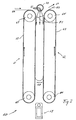
- FIG. 2 shows a section in a schematic representation by a storage device 60 which is suitable as Foil feed storage device 16 or as a film removal storage device 19 to be used.
- the storage device 60 is formed from the two traction devices 61 and 62 and the fan rail 70.
- the at least one material web 65 is on the startup page 66 of the memory device 60 fed and leaves this on the discharge side 67.
- Each the two pulling devices 61, 62 consist of a pair Casters 64, at least one of which is driven, and a conveyor belt 63.
- the conveyor belt 63 runs around the two rollers 64 of the traction device around.
- the fan rail 70 extends in width across the width of the Conveyor belts 63 and thus determines the width that the may have at least one material web 65 to pass through the To be conveyable through storage device 60.
- the Fan rail 70 has air outlet openings over its entire width 72, from which an air stream emerges which the material web to the conveyor belts 63 of the pulling devices 61, 62 presses. Due to the air flow 71 Material web 65 pressed against the conveyor belts 63 that the material web 65 is moved into the storage device is being exercised, with a steady pull resulting from Airflow 71 flow velocity, movement velocity of conveyor belts 63 and friction between Conveyor belt 63 and material web 65 results.
- the air outlet openings 72 of the fan rail 70 can be in be formed in different ways. It can happen for example around air outlet holes or around air outlet slots act.
- the air outlet openings 72 must be but be designed so that in the area between the traction devices 61 and 62 as uniform as possible, laminar air flow results. Furthermore, the air flow must not only on the space between the train devices 61, 62 aligned, but also on the conveyor belts of the pulling devices must be executed to an adequate extent Contact pressure for the material web 65 on the conveyor belts 63 to reach.
- Detection device 69 is provided, which is the distance to the between the traction devices 61, 62 free loop section 68 of the material web 65 detected. Become multiple webs of material 65 simultaneously in the storage device 60 stored, the detection device 69 is preferred Form so that they are the distance to the free loop sections 68 each web of material either simultaneously or cyclically in succession at a sufficient speed detected. This may be necessary in the detection device 69 to provide several sensors for distance measurement.
- FIG. 3 shows a further exemplary embodiment of a Storage device 60.
- This storage device 60 also essentially consists of two pulling devices 61 and 62 and a fan rail 70 is formed. Unlike that 2 has the pulling device 62 on the outlet side 67 of the at least one material web 65 additionally a suction box 73.
- the at least one Material web 65 is the storage device 60 on the Start page 66 fed. Through the air flow 71, which of the Blower rail 70 is generated, the web of material to the The conveyor belt 76 of the pulling device 61 is pressed. The The conveyor belt 76 of the pulling device 61 moves as well the conveyor belt 63 of the traction device 62 parallel to Air flow direction.
- the enlargement of the Pressure difference corresponds to an increase in the contact pressure of the Material web 65 to the conveyor belt 63 of the traction device 62.
- This measure may also contribute to the Relative movement between the conveyor belt 63 of the traction device 62 and to reduce the at least one material web 65.
- a relative speed between the conveyor belt 63 and the at least one material web 65 consists alone if only because the direction of movement of the conveyor belt 63 opposite to the direction of movement of the material web 65 is directed along the conveyor belt 63.
- blower rail 70 In order to load the material web as evenly as possible To reach 65 through the airflow 71, it can be advantageous be the blower rail 70 at several locations blowing air supply.
- the fan rail 70 can also be in a number divided by segments, each segment using a can have their own air supply, so that the air flow 71 of the through the air outlet openings 72 of the fan rail in Direction toward web 65 exits at everyone Segment can be another. This can then be the case, for example be advantageous if there are several in the storage device 60 Material webs 65 of different characteristics are temporarily stored become.
- a camera 75 On the side of the traction device facing away from the material web 65 61 is as a detection device 69 for the free Loop section 68 of the material web 65 a camera 75 arranged. So that the camera 75 the position of the free loop section between the two pulling devices 61 and 62 can detect, the conveyor belt 76 is transparent educated. The camera has to depend on your Observation opening angle 77 may be arranged so that it the position of the free loop section 68 of the at least a material web 65 between the rollers 64 of the conveyor belt 63 or the transparent conveyor belt 76 can capture. The camera can also extend in the direction of extension the fan rail 70 has such an opening angle or one have such a distance from the transparent conveyor belt 76, that the entire width in the at least one web of material 65 can be performed.
- the camera is in the Position, at the same time the position of the free loop sections 68 of several material webs 65 to be detected. Over a suitable, not shown image evaluation device can then the position as well as the change in position of the free Loop sections 68 are evaluated.
- the camera 75 is thus an example of a detection device 69 that is able to simultaneously position several material webs 65 in the memory device 60.
- the loop section over the substantial part of its length, with the exception of the free Loop section, guided and held securely so that especially touching the loop legs, for example due to electrostatic attraction, reliable is avoided.
- the non-guided, free loop section on the other hand stands calmly and flutter-free between the Suction belts and can be used as a well-detectable reference surface for the distance measurement using the one aimed at him Serve sensor device.
- the positionally reliable web guide can be guaranteed without special sealing measures, such as they are required for vacuum accumulators.
- foil webs of other widths without Effort possible because there are no side walls that limit the path must be provided.
- the storage capacity of the film storage to determine the total length of feed of the store that it is not for memory overcrowding or for complete Emptying of the memory can come.
- the storage dimension can be reduced by filling and / or filling or emptying speed of a memory by means of the Sensor device 50 monitors and, for example, the rolling speed the unwind storage roll 15 depending is controlled by filling level and / or filling speed.
- On Distance sensor is particularly advantageous for this, because not only the absolute levels, given by the (vertical) Position of the free loop section, detected can be, but by observing the temporal Course of the distance in particular also filling and emptying speeds.
Landscapes
- Physics & Mathematics (AREA)
- Fluid Mechanics (AREA)
- Controlling Rewinding, Feeding, Winding, Or Abnormalities Of Webs (AREA)
- Advancing Webs (AREA)
- Folding Of Thin Sheet-Like Materials, Special Discharging Devices, And Others (AREA)
- Input Circuits Of Receivers And Coupling Of Receivers And Audio Equipment (AREA)
Abstract
Description
Die Erfindung betrifft eine Speichereinrichtung zur Aufnahme eines Schlaufenabschnitts wenigstens einer bewegten flexiblen Materialbahn, insbesondere einer Prägefolienbahn, zwischen einem der Speichereinrichtung vorgeschalteten Zufuhrbereich, in dem die Materialbahn mit einer Zufuhrbahngeschwindigkeit bewegt wird, und einem nachgeschalteten Abfuhrbereich, in dem die wenigstens eine Materialbahn mit einer mindestens zeitweise von der Zufuhrbahngeschwindigkeit abweichenden Abfuhrbahngeschwindigkeit bewegt wird.The invention relates to a storage device for recording a loop section of at least one moving flexible Material web, in particular an embossing film web, between a feed area upstream of the storage device, in which the material web at a feed web speed is moved, and a downstream discharge area in which the at least one material web with an at least temporarily discharge path speed deviating from the feed path speed is moved.
Derartige Speichereinrichtungen können nach Art von Ausgleichsbehältern oder Materialpuffern dazu dienen, in einer Einrichtung zur Verarbeitung des in Form wenigstens einer flexiblen Materialbahn vorliegenden Materials Bereiche zumindest zeitweise unterschiedlicher Materialbahngeschwindigkeiten voneinander zu trennen. Die Anpassung der unterschiedlichen Geschwindigkeiten kann dadurch erfolgen, daß die Speichereinrichtung einen mehr oder weniger langen Schlaufenabschnitt der Materialbahn aufnimmt und auf diese Weise Geschwindigkeitsdifferenzen zwischen Zufuhrseite und Abfuhrseite ausgleicht, ohne daß es zur Stauchung oder zu unzulässiger Zugbeanspruchung der Materialbahn kommt. Such storage devices can be of the type of expansion tanks or material buffers are used in one Device for processing the in the form of at least one flexible material web present material areas at least temporarily different material web speeds separate from each other. Adapting the different Speeds can take place in that the Storage device a more or less long loop section the web of material and in this way Speed differences between the supply side and the discharge side compensates without being too compressible or too impermissible Tensile stress on the material web comes.
Bekannte Speichereinrichtungen dieser Art haben einen Unterdruckbehälter, in den ein Schlaufenabschnitt der Materialbahn hineingesogen wird. Am Eingangsbereich des Unterdruckbehälters wird der Schlaufenabschnitt an zwei Stellen, beispielsweise an Umlenkrollen gehalten, während der dazwischenliegende Schlaufenabschnitt durch Unterdruck gestrafft wird. Dabei wirkt der mehr oder weniger tief eingesogene Schlaufenabschnitt wie ein Kolben, während der zugehörige Zylinder durch die glattwandigen Behälterwände gebildet wird. Zur Vermeidung des Einziehens von Nebenluft müssen die den Bahnkanten zugewandten Behälterwände möglichst nahe zum Rand der Materialbahn angeordnet sein, so daß die Breite einer Unterdruckkammer zweckmäßig die Breite der gespeicherten Materialbahn nur geringfügig übersteigt. Weil die Saugkammerbreite sehr genau an die Breite der Materialbahn angepaßt werden muß, müssen beim Wechsel von einer Materialbahnbreite auf eine andere Speichereinrichtungen entsprechend ausgetauscht oder umgerüstet werden, indem Kammerwände manuell versetzt werden, um die Kammerbreite an die Breite der neuen Materialbahn anzupassen. Derartige Unterdruckspeicher sind beispielsweise aus den europäischen Patentanmeldungen 0 176 905 , die als nächstliegender Stand der Technik angesehen wird, oder EP 0 623 432 bekannt und haben sich bei relativ steifem bzw. festem Material, wie Papier oder fotografischem Filmmaterial, gut bewährt. Aus der EP 0 718 099 ist bekannt, daß derartige Unterdruckspeicher auch als Folienspeicher zur Speicherung von Prägefolienbahnabschnitten in einer Präge-Rotationsmaschine verwendet werden können. Bei relativ dünnem, empfindlichen Prägefolienmaterial ist jedoch zur Vermeidung von Beschädigungen des Folienmaterial ggf. erhöhter konstruktiver und/oder steuerungstechnischer Aufwand erforderlich. Bei unzureichendem Bahnzug kann es zu einem Flattern des sehr leichten, biegeschlaffen Folienmaterials im Luftstrom der eingesaugten Luft kommen, wodurch eine Prägefolienbahn beschädigt und/oder die Einzugskraft der Speichereinrichtung unkontrollierbar beeinträchtigt werden kann.Known storage devices of this type have a vacuum container, into a loop section of the material web is sucked in. At the entrance area of the vacuum tank the loop section is in two places, for example held on pulleys while the one in between Loop section is tightened by negative pressure. there the more or less deeply drawn loop section works like a piston while the associated cylinder passes through the smooth-walled container walls is formed. To avoid the intake of secondary air must the the web edges facing container walls as close as possible to the edge of the material web be arranged so that the width of a vacuum chamber expediently the width of the stored material web only slightly exceeds. Because the suction chamber is very wide must be adapted exactly to the width of the material web, when changing from a web width to a other storage devices replaced accordingly be converted by manually moving chamber walls, by the chamber width to the width of the new material web adapt. Such vacuum accumulators are, for example from European patent applications 0 176 905 which is considered the closest prior art, or EP 0 623 432 and have proven to be relatively stiff or solid material, such as paper or photographic film material, well proven. It is known from EP 0 718 099 that such Vacuum storage also as foil storage for storage of stamping foil web sections in a stamping rotary machine can be used. With relatively thin, sensitive stamping foil material is however to avoid of damage to the film material, possibly more constructive and / or control engineering effort required. If the train is inadequate, the very flutter can occur light, limp film material in the air flow of the sucked air come in, creating an embossed film damaged and / or the retraction force of the storage device can be affected uncontrollably.
Der Erfindung liegt die Aufgabe zugrunde, eine Speichereinrichtung zu schaffen, die die Nachteile des Standes der Technik vermeidet. Insbesondere soll die Speichereinrichtung eine problemlose Speicherung von dünnem, empfindlichen Prägefolienmaterial ggf. in mehreren parallel zueinander verlaufenden Materialbahnen ermöglichen.The invention has for its object a storage device to create the disadvantages of the prior art Technology avoids. In particular, the storage device easy storage of thin, sensitive Stamping foil material, if necessary, in several parallel to each other allow running material webs.
Zur Lösung dieser Aufgabe schlägt die Erfindung eine Speichereinrichtung mit den Merkmalen von Anspruch 1 vor.To achieve this object, the invention proposes a storage device with the features of claim 1.
Bei einer erfindungsgemäßen Speichereinrichtung gemäß dem Anspruch 1 ist zufuhrseitig eine erste Zugeinrichtung zum Ziehen der wenigstens einen Materialbahn Richtung Speichereinrichtung und abfuhrseitig eine gesonderte, zweite Zugeinrichtung zum Ziehen der wenigstens einen Materialbahn Richtung Speichereinrichtung vorgesehen. Zwischen den bezogen auf die Bahnlaufrichtung einander entgegengesetzt bzw. aufeinander zu wirkenden Zugeinrichtungen, die auf einem großen Teil der Länge des Schlaufenabschnitts flächig und schonend an diesem angreifen können, verbleibt ein freier Schlaufenteilabschnitt, der im wesentlichen frei von Zugkräften ist. Er kann im Verhältnis zur Gesamtlänge des Schlaufenabschnittes sehr kurz sein und durch die Eigenspannung des Materialbahnmaterials gehalten ruhig und flatterfrei verbleiben. Die an den freien Schlaufenteilabschnitt angrenzenden Schlaufenteilabschnitte, an denen die zugeinrichtungen flächig angreifen, können durch die Zugeinrichtungen in einem Abstand zueinander aktiv auseinandergehalten werden. Dadurch kann insbesondere die Gefahr einer gegenseitigen Berührung dieser Schlaufenschenkel beispielsweise aufgrund elektrostatischer Kräfte vermieden.werden. Diese Gefahr kann bei Unterdruckspeichern auftreten, bei denen die gesamte Länge des Schlaufenabschnittes ungeführt bzw. frei ist und sich entsprechend die Schlaufenform aus der Wechselwirkung zwischen Bahnspannungskräften und durch Unterdruck verursachten Einsaugkräften ergibt.In a storage device according to the invention Claim 1 is a first pulling device on the feed side Pull the at least one material web towards the storage device and a separate, second pulling device on the discharge side for pulling the at least one material web direction Storage device provided. Between the related opposite to each other in the direction of web travel or interacting pulling devices on a large part of the length of the loop section and flat can gently attack this, there remains a free one Loop section that is essentially free of tensile forces is. It can be in relation to the total length of the loop section be very short and due to the inherent tension of the Material web material kept calm and flutter-free. Those adjacent to the free loop section Loop sections on which the traction devices can attack flatly by the pulling devices in one Distance from each other can be kept apart actively. Thereby can in particular be the risk of mutual contact this loop leg, for example, due to electrostatic Forces are avoided. This danger can Vacuum accumulators occur in which the entire length of the loop section is unguided or free and itself correspondingly the loop shape from the interaction between web tension forces and caused by negative pressure Suction forces results.
Eine bevorzugte Ausführungsform zeichnet sich dadurch aus, daß die erste Zugeinrichtung und/oder die zweite Zugeinrichtung mindestens eine in eine Einzugrichtung bewegbare, vorzugsweise abschnittsweise ebene Antriebsfläche sowie Andruckmittel zum flächigen Andrücken der Materialbahn an die Antriebsfläche aufweist. Die Zugkraft einer Zugeinrichtung kann somit über einen großen bzw. langgestreckten Flächenbereich schonend auf die wenigstens eine Materialbahn übertragen werden. Durch das Anliegen an den mit Abstand zueinander angeordneten Antriebsflächen können die entsprechenden Schlaufenschenkel aktiv sicher auseinander gehalten werden. Dabei wird vorzugsweise unter Aufbau von Gleitreibung zwischen der wenigstens einen Materialbahn und Antriebsfläche ein Schlupfantrieb gebildet. Der Aufbau von Gleitreibung unter Vermeidung von Haftreibung fördert ein sanftes, ruckfreies und das Materialbahnmaterial schonendes Fördern der wenigstens einen Materialbahn und kann zweckmäßig dadurch erreicht werden, daß die Geschwindigkeit der Antriebsfläche in Einzugsrichtung größer ist als die durch die Transportmittel vorgegebene Geschwindigkeit der Materialbahn in diese Richtung. Vorzugsweise weist die erste Zugeinrichtung und/oder die zweite Zugeinrichtung mindestens ein umlaufendes, mit jeweils einem ebenen Abschnitt seiner Außenfläche die Antriebsfläche bildendes Transportband auf.A preferred embodiment is characterized in that that the first traction device and / or the second traction device at least one movable in a feed direction, preferably in sections flat drive surface and Pressure means for pressing the material web flat against the Has drive surface. The tractive force of a traction device can thus over a large or elongated area gently transferred to the at least one material web become. By being close to each other arranged drive surfaces can the corresponding Loop legs are actively kept apart safely. It is preferably under the formation of sliding friction between the at least one material web and drive surface a slip drive formed. The development of sliding friction while avoiding static friction promotes a gentle, jerk-free and the material web material gentle conveying of at least one web of material and can be useful achieved that the speed of the drive surface in the feed direction is greater than that of the means of transport predetermined speed of the material web in this Direction. The first traction device preferably has and / or the second traction device has at least one rotating, each with a flat section of its outer surface the conveyor belt forming the drive surface.
Zur Erzeugung des erforderlichen Andrucks der wenigstens einen Materialbahn auf die Antriebsfläche ist vorzugsweise vorgesehen, daß die Andruckmittel eine Saugeinrichtung zur Ansaugung der wenigstens einen Materialbahn an die Antriebsfläche umfassen, die zwischen Materialbahn und Antriebsfläche einen Unterdruck erzeugt.To generate the necessary proof of the least a web of material on the drive surface is preferred provided that the pressure means a suction device for Suction of the at least one material web on the drive surface include that between material web and drive surface creates a negative pressure.
Alternativ oder zusätzlich ist es auch möglich, beispielsweise durch ein Gebläse über eine Luftströmung die wenigstens eine Materialbahn von der antriebsflächenabgewandten Seite auf die Antriebsfläche zu drücken. Derartige berührungslos arbeitende Andruckmittel sind wegen der dadurch erreichbaren Schonung der wenigstens einen Materialbahn bevorzugt. Eine derartige Luftströmung kann insbesondere durch eine Gebläseschiene erfolgen, die zwischen den beiden Zugeinrichtungen angeordnet ist und quer zu der Förderrichtung der wenigstens einen Materialbahn in diesem Bereich verläuft. Die wenigstens eine Materialbahn wird zwischen Gebläseschiene und den beiden Zugeinrichtungen hindurchgeführt. Der Luftstrom tritt aus der Gebläseschiene in Richtung auf die beiden Zugeinrichtungen hin aus, wodurch die wenigstens eine Materialbahn an die Zugeinrichtungen angedrückt wird. Die Verwendung einer Gebläseschiene ist dann von besonderem Vorteil, wenn mehrere gegebenenfalls unterschiedlich breite Materialbahnen in ein und derselben Speichereinrichtung zwischengespeichert werden sollen. Es ist dabei nicht erforderlich, eng an die Materialbahn anliegende Leitflächen vorzusehen, um die Druckdifferenz zwischen Antriebsflächen abgewandter Ausblasseite der Gebläseschiene und Antriebsflächen zugewandter Seite der Zugeinrichtungen aufrecht zu erhalten. Dies verringert unter anderem die Umrüstzeiten, wenn neue Materialbahnen anderer Breite durch den Speicher hindurchgeführt werden sollen. In einfachster Ausführung sind die Zugeinrichtungen dann als feststehende Seitenwände ausgebildet, an die sich die wenigstens eine Materialbahn anlegt und entlanggleitet. Alternatively or additionally, it is also possible, for example by a fan over an air flow which at least a material web from the side facing away from the drive surface to press on the drive surface. Such contactless Working pressure means are because of the achievable Protection of the at least one material web is preferred. A such air flow can in particular through a fan rail take place between the two train devices is arranged and transverse to the conveying direction of the at least a web of material runs in this area. At least a web of material is placed between the fan rail and the two Pulling devices passed through. The airflow emerges from the Fan rail in the direction of the two pulling devices out, whereby the at least one material web to the Pulling devices is pressed. The use of a Fan rail is particularly advantageous if several if necessary, different widths of material in one and the same storage device are temporarily stored should. It is not necessary to be close to the material web Provide adjacent guiding surfaces to the pressure difference between the drive surfaces facing away from the exhaust side of the fan rail and drive surfaces facing the side of the traction devices to maintain. This diminishes below the changeover times when new material webs from others Width to be passed through the memory. In The simplest design are the pulling devices fixed side walls to which the at least creates a material web and slides along it.
Die Andruckmittel können aber auch über Berührung arbeitende Andruckelemente, beispielsweise Andruckbürsten o. dgl. aufweisen.The pressure means can also work by touch Pressure elements, for example pressure brushes or the like. exhibit.
Für eine besonders schonende und gleichzeitig sichere Führung der wenigstens einen Materialbahn in der Speichereinrichtung können mit Vorteil Mittel zur Einstellung der Zugkraft für die erste Zugeinrichtung und/oder die zweite Zugeinrichtung vorgesehen sein, über die sich beispielsweise in Abhängigkeit von der mittleren Transportgeschwindigkeit in Haupttransportrichtung und/oder dem Materialbahnmaterial die Zugkräfte optimieren lassen. Eine Steuerung der Stärke der Gleitreibung zwischen Materialbahn und Antriebsfläche kann beispielsweise über die Vorschubgeschwindigkeit des Transportbandes und/oder über die Saugkraft der Saugeinheit und/oder den Luftstrom der Gebläseschiene erfolgen.For particularly gentle and safe guidance the at least one material web in the storage device can be advantageous means for adjusting the tractive force for the first traction device and / or the second traction device be provided, for example depending on from the average transport speed in the main transport direction and / or the material web material the tensile forces get optimized. A control of the strength of the sliding friction between material web and drive surface can for example about the feed speed of the conveyor belt and / or about the suction power of the suction unit and / or the air flow of the Fan rail done.
Eine bevorzugte Ausführungsform zeichnet sich dadurch aus, daß die Antriebsflächen der ersten Zugeinrichtung und der zweiten Zugeinrichtung einander zugewandt sind und/oder im wesentlichen parallel zueinander verlaufen. Die Antriebsflächen können also als in Einzugsrichtung bewegliche Wände wirken, zwischen denen der Schlaufenabschnitt etwa U-förmig mit im wesentlichen geraden Schenkeln verläuft. Ein den Abstand der Schlaufenschenkel bestimmender Abstand zwischen den Antriebsflächen kann zweckmäßig derart groß gewählt werden, daß der freie Schlaufenteilabschnitt, in dem die wenigstens eine Materialbahn an keiner Antriebsfläche anliegt, durch die Eigenspannung des Materials selbst gehalten wird und das Material knickfrei ausschließlich elastisch gekrümmt wird. Andererseits kann ggf. der Abstand derart klein gewählt werden, daß sich Änderungen der Geschwindigkeitsunterschiede zwischen Zufuhr- und Abfuhrbereich in einer deutlichen, ggf. durch eine Sensoreinreichtung zuverlässig erfaßbaren Verlagerung des freien Schlaufenteilabschnittes innerhalb der Speichereinrichtung parallel zur Einzugsrichtung bemerkbar macht.A preferred embodiment is characterized in that that the drive surfaces of the first traction device and second traction device are facing each other and / or in run essentially parallel to each other. The drive surfaces can be used as movable walls in the feed direction act between which the loop section is approximately U-shaped runs with essentially straight legs. A den Distance between the loop legs determines the distance between the drive surfaces can suitably be chosen as large be that the free loop section in which the at least one material web is not in contact with any drive surface, held by the internal stress of the material itself and the material is only elastic without kinks is curved. On the other hand, the distance may be such be chosen small that changes in speed differences between supply and discharge area in one clear, possibly reliable by a sensor device detectable displacement of the free loop section within the storage device parallel to the feed direction noticeable.
Die Speicherkapazität kann so ausgelegt sein, daß für alle Betriebsbedingungen ausreichend Speicherraum vorhanden ist und weder eine Überfüllung, noch eine vollständige Entleerung des Speichers eintritt. Vorzugsweise kann jedoch der Grad der Speicherfüllung überwacht werden, um ggf. zufuhrseitig und/oder abfuhrseitig durch entsprechende Ansteuerung der Bahntransportmittel Materialbahngeschwindigkeitsänderungen vornehmen zu können. Bei einer bevorzugten Ausführungsform ist zur Erfassung der Speicherfüllung eine Sensoreinrichtung vorgesehen, die mindestens einen Abstandssensor zur Erfassung eines insbesondere parallel zur Einzugsrichtung gemessenen Abstandes zwischen einem freien Schlaufenteilabschnitt und einer Bezugsposition aufweist. Ein Abstandssensor ermöglicht nicht nur eine einfache Erfassung des absoluten Füllgrades einer Speichereinrichtung, sondern insbesondere auch eine problemlose Erfassung der Dynamik der Speicherfüllung, also eine Erfassung der Geschwindigkeit, mit der sich ein Speicher füllt oder entleert. Es ist auch möglich, eine der beiden Zugeinrichtungen oder beide Zugeinrichtungen aus transparentem Material - beispielsweise aus einer durchsichtigen Folie, die um zwei Rollen herumgeführt ist und im Kreis läuft, wobei wenigstens eine der beiden Rollen angetrieben ist und die in dem Bereich zwischen den zwei Rollen transparent ist - zu fertigen, und die Lage der wenigstens einen Materialbahn über eine Kamera zu erfassen, die auf der Materialbahn abgewandten Seite der transparenten Zugeinrichtung angeordnet ist. Dies ist insbesondere dann von Vorteil, wenn die Lage mehrerer Materialbahnen in der selben Speichereinrichtung gleichzeitig überwacht werden soll. Die Erfassung der Speicherfülldynamik ermöglicht eine "vorausschauende" Steuerung von Materialzufuhr und/oder Materialabfuhr zur Speichereinrichtung, indem nicht erst bei Erreichen eines zulässigen maximalen Füllgrades entsprechende Steuersignale an eine Steuereinheit abgegeben werden, sondern auch schon bei schneller Annäherung an einen Extremzustand der Speicherfüllung.The storage capacity can be designed so that for everyone Operating conditions there is sufficient storage space and neither overfilling nor complete emptying of the memory occurs. However, the degree of Storage fill to be monitored, if necessary, on the supply side and / or discharge side by appropriate control of the Railway transport material material speed changes to be able to make. In a preferred embodiment is a sensor device for detecting the storage filling provided the at least one distance sensor for detection one measured in particular parallel to the feed direction Distance between a free loop section and has a reference position. A distance sensor enables not just a simple record of the absolute filling level a storage device, but in particular also a easy recording of the dynamics of the memory filling, so a capture of the speed at which a memory is fills or empties. It is also possible to use one of the two Pulling devices or both pulling devices made of transparent Material - for example from a transparent Foil that is wrapped around two rolls and in a circle runs, with at least one of the two rollers driven and which is transparent in the area between the two roles is - to manufacture, and the location of at least one Capture material web via a camera that is on the Side of the transparent pulling device facing away from the material web is arranged. This is particularly advantageous if the position of several material webs in the same storage device should be monitored at the same time. The capture the memory filling dynamics enables a "predictive" Control of material supply and / or material removal for Storage device by not only when a permissible maximum filling levels corresponding control signals to a control unit, but also already when rapidly approaching an extreme state of memory filling.
Eine bevorzugt berührungslos arbeitende Sensoreinrichtung zeichnet sich dadurch aus, daß sie mindestens einen Wellenerzeuger zur Erzeugung elektromagnetischer und/oder akustischer Wellen aufweist und daß vorzugsweise mindestens eine Empfangseinrichtung zum Empfang von durch den freien Schlaufenteilabschnitt reflektierten Wellen vorgesehen ist. Insbesondere kann die Abstandsmessung mit Hilfe mindestens einer Laserlichtquelle vorgenommen werden, wobei insbesondere mindestens eine Fotodiode als Empfänger dienen kann. Bei einer Abstandsmessung über Wellen läßt sich besonders einfach über Nutzung des Doppeleffekts auch die Geschwindigkeit des Füllens bzw. Leerens der Speichereinrichtung ableiten und berücksichtigen.A preferably non-contact sensor device is characterized in that it has at least one wave generator to generate electromagnetic and / or acoustic Has waves and that preferably at least one Receiving device for receiving through the free loop section reflected waves is provided. In particular can measure the distance using at least one Laser light source are made, in particular at least one photodiode can serve as a receiver. at a distance measurement via waves is particularly easy using the double effect also the speed of the Derive filling or emptying of the memory device and consider.
Zur Erzielung höherer Produktivität ist es häufig erwünscht, in einer das Materialbahnmaterial nutzenden Einrichtung mehrere Materialbahnen parallel zu verarbeiten. Eine entsprechende Speichereinrichtung kann vorzugsweise zur Speicherung mehrerer paralleler, vorzugsweise unabhängig voneinander bewegbarer Materialbahnen ausgebildet sein. Während bei herkömmlichen Unterdruckspeichern hierzu zwischen den einzelnen Materialbahnen Trennwände in geeigneten Abständen vorgesehen sein müssen, um ein sicheres Einsaugen unter Vermeidung des Einziehens von Nebenluft zu gewährleisten, ist dies bei erfindungsgemäßen Speichereinrichtungen nicht erforderlich, da insbesondere eine Zugeinrichtung mit Schlupfantrieb an mehreren, ggf. mit unterschiedlichen Geschwindigkeiten bewegten Materialbahnen gleichzeitig ziehen kann, wobei sich ggf. die Geschwindigkeitsunterschiede zwischen einer Antriebsfläche und der gezogenen Materialbahn von Bahn zu Bahn unterscheiden.To achieve higher productivity, it is often desirable to in a facility using the material web material to process several material webs in parallel. A corresponding Storage device can preferably be used for storage several parallel, preferably independently movable material webs can be formed. While at conventional vacuum storage for this purpose between the individual Material webs partition walls are provided at suitable intervals must be to avoid safe suction to ensure the intake of secondary air, this is at storage devices according to the invention not required, because in particular a pulling device with slip drive several, possibly with different speeds can move moving material webs simultaneously, whereby possibly the speed differences between a drive surface and the web of material drawn from web to web differ.
Obwohl es möglich ist, für jede Materialbahn eine gesonderte Sensoreinrichtung zur Erfassung der Speicherfüllung vorzusehen, ist es besonders vorteilhaft, wenn die Sensoreinrichtung zur zeitlich aufeinanderfolgenden Erfassung der Speicherfüllung bei mindestens zwei parallel zueinander und vorzugsweise unabhängig voneinander bewegbaren Materialbahnen zwischen den Materialbahnbereichen verfahrbar ist. Diese nicht nur bei erfindungsgemäßen Speichern, sondern auch bei herkömmlichen Speichereinrichtungen, beispielsweise Saugluftspeichern sehr vorteilhafte Maßnahme spart auf Seiten der verwendeten Hardware, also der Sensorik, Kosten und konstruktiven Aufwand, da ggf. ein einziger Sensor ausreichen kann, um eine Vielzahl von Materialbahnen zu überwachen. Ein Sensor ist zweckmäßig signalübertragend mit einer Steuer- und Auswerteeinheit verbunden, über die die Materialbahngeschwindigkeit zufuhrseitig und/oder abfuhrseitig gesteuert werden kann. Bei mehreren durch einen Sensor überwachten Materialbahnen kann die Zuordnung der Füllgradmeßwerte, insbesondere der Abstandsmeßwerte, innerhalb der Steuereinrichtung kostengünstig durch entsprechende Software vorgenommen werden.Although it is possible to have a separate one for each material web To provide a sensor device for detecting the storage filling, it is particularly advantageous if the sensor device for sequential acquisition of the storage fill with at least two parallel to each other and preferably independently movable material webs between the Material web areas is movable. This not only at memories according to the invention, but also in conventional Storage devices, for example suction air stores very much advantageous measure saves on the part of the used Hardware, i.e. the sensors, costs and design effort, since a single sensor may be sufficient to detect one Monitor a variety of material webs. A sensor is expediently signal-transmitting with a control and evaluation unit connected over which the material web speed can be controlled on the supply side and / or discharge side. at several material webs monitored by a sensor the assignment of the degree of filling measurements, in particular the distance measurements, inexpensive within the control device be made by appropriate software.
Speichereinrichtungen der genannten Art können bei allen Einrichtungen eingesetzt werden, bei denen eine Speicherung von Abschnitten durchlaufender Materialbahnen erforderlich ist, also beispielsweise bei Druckmaschinen, Verpackungsmaschinen, Prägemaschinen o. dgl. Da sowohl einfuhrseitig, als auch abfuhrseitig Material unter geeigneter Zugkraft in die Speichereinrichtung eingezogen werden kann, lassen sich selbst komplizierte Geschwindigkeitsverhältnisse zwischen Zufuhr- und Abfuhrseite jederzeit einfach kompensieren. So kann beispielsweise zufuhrseitig Material kontinuierlich zugeführt und abfuhrseitig intermittierend oder mit wechselnder Geschwindigkeit abgeführt werden. Es ist auch möglich, eine diskontinuierliche Materialzufuhr an eine diskontinuierliche oder kontinuierliche Materialabfuhr anzupassen.Storage devices of the type mentioned can with all Facilities are used where storage of sections of continuous material webs required is, for example in printing machines, packaging machines, Embossing machines or the like. Since both on the import side and material on the discharge side with suitable tensile force into the Storage device can be retracted even complicated speed ratios between Simply compensate the supply and discharge side at any time. So can continuously feed material, for example supplied and intermittent or alternating on the discharge side Speed can be dissipated. It is also possible, a discontinuous material supply to a discontinuous or adapt continuous material removal.
Mit besonders großen Vorteilen können erfindungsgemäße Speichereinrichtungen bei Prägevorrichtungen, insbesondere Heißprägevorrichtungen eingesetzt werden. Eine derartige Prägevorrichtung hat ein Prägewerk, bei dem zwischen einem Prägezylinder und einem Gegendruckelement, insbesondere einem Gegendruckzylinder, ein Prägespalt gebildet ist. Weiterhin ist eine Transporteinrichtung zum Transport einer Prägefolienbahn von einem Folienvorrat durch den Prägespalt zu einer Foliensammeleinrichtung vorgesehen, wobei die Transportvorrichtung Folienbeschleunigungsmittel aufweist, die derart ausgebildet sind, daß sich die Prägefolienbahn zumindest während eines Prägeintervalls geschwindigkeitsgleich mit einer zu beprägenden Materiallage durch den Prägespalt bewegt. Dies ist erforderlich, damit das Prägegut, beispielsweise diskrete hintereinanderliegende Prägeeinheiten wie Bilder oder Texte, oder aber ein aufzuprägender Teil einer Farbschicht, unverzerrt bzw. unverschmiert auf die zu beprägende Materiallage übertragen werden kann und damit die Prägefolienbahn während des Prägeintervalls nicht reißt. Eine erfindungsgemäße Prägevorrichtung zeichnet sich dadurch aus, daß zwischen dem Folienvorrat und den Folienbeschleunigungsmitteln und/oder zwischen den Folienbeschleunigungsmitteln und der Foliensammeleinrichtung mindestens eine Speichereinrichtung der beschriebenen Art angeordnet ist.With particularly great advantages can Storage devices for embossing devices, in particular Hot stamping devices are used. Such Embossing device has an embossing unit, in which between one Embossing cylinder and a counter pressure element, in particular one Impression cylinder, an embossing gap is formed. Farther is a transport device for transporting an embossing foil web from a film supply through the embossing gap to one Foil collecting device provided, the transport device Has film acceleration means that such are designed so that the embossing film web at least at the same speed as during an embossing interval a material layer to be embossed through the embossing gap emotional. This is necessary so that the embossed product, for example discrete embossing units in series like Pictures or texts, or a part of one to be stamped Color layer, undistorted or not smeared on the one to be embossed Material layer can be transferred and thus the Stamping foil web does not tear during the stamping interval. A Embossing device according to the invention is characterized in that that between the film supply and the film accelerators and / or between the film accelerators and the film collecting device at least one storage device the type described is arranged.
Bei Prägefolienbahnen mit diskreten Prägeeinheiten wird eine möglichst gute Registerhaltigkeit, also eine Lagegenauigkeit der Prägeeinheit zum vorgesehenen Prägeort, angestrebt. Bei Prägefolien mit Farbschichten dagegen strebt man zur Minimierung von Ausschuß mit nicht benutzten Farbschichtbereichen einen möglichst geringen Abstand nachfolgender, noch zu prägender Farbschichtbereiche von vorhergehenden, bereits durch Prägung entfernten Farbschichtbereichen an. Um Material zu sparen, wird angestrebt, daß hintereinander liegende zu prägende Farbschichtbereiche bzw. Prägeeinheiten auf der Prägefolienbahn enger zusammenliegen als hintereinander liegende Prägeorte auf der Materiallage. Dies macht es erforderlich, daß die Prägefolienbahn außerhalb des Prägeintervalls langsamer als die normalerweise gleichförmig bewegte Materiallage geführt wird, vor dem Prägeintervall auf die Materiallagengeschwindigkeit beschleunigt wird und anschließend wieder abgebremst und ggf. auch zurückgezogen wird. Diese Geschwindigkeitsänderungen werden durch die Folienbeschleunigungsmittel bewirkt, wobei unter Folienbeschleunigung sowohl eine Geschwindigkeitssteigerung, als auch eine Geschwindigkeitsverringerung, als auch eine Richtungsumkehr der Bewegung der Prägefolienbahn verstanden wird. Bei einer bevorzugten Ausführungsform sind entsprechend die Folienbeschleunigungsmittel zur Erzeugung einer ungleichmäßigen Bewegung der Materialbahn ausgebildet, vorzugsweise zur Erzeugung einer Vorwärts/Rückwärtsbewegung, bei der die Materialbahn zeitweise in einer der Haupt-Transportrichtung entgegengesetzten Rückwärtsrichtung bewegt wird. Hier machen sich die Vorteile erfindungsgemäßer Speichereinrichtungen besonders bemerkbar, da durch die Möglichkeit des beidseitigen, unabhängigen Einzugs von Bahnmaterial in den Folienspeicher sowie die durch den Schlupf gegebene Möglichkeit, Material entgegen der Einzugsrichtung im wesentlichen verzerrungsfrei aus der Speichereinrichtung herauszuziehen, auch Materialbahnbewegungen entgegen der Haupt-Transportrichtung problemlos akkomodiert werden können. For embossing foil webs with discrete embossing units, a the best possible register accuracy, i.e. an exact position the stamping unit to the intended stamping location. at Embossing foils with layers of color, on the other hand, are aimed at minimizing from rejects with unused paint layer areas the smallest possible distance behind, still too defining color layer areas from previous ones, already areas of ink layer removed by embossing. To material to save, it is sought that one behind the other embossing color layer areas or embossing units on the Embossing foil web lie closer together than one behind the other Horizontal embossing locations on the material layer. It does it required that the stamping foil web be outside the stamping interval slower than the one moving normally Material position is performed before the embossing interval on the Material layer speed is accelerated and then is braked again and possibly also withdrawn. These speed changes are caused by the film acceleration means causes, under film acceleration both an increase in speed and a decrease in speed, as well as a reversal of direction Movement of the embossing foil web is understood. At a the film acceleration means are accordingly preferred to produce an uneven Movement of the material web is formed, preferably for Generation of a forward / backward movement in which the Material web at times in one of the main transport directions opposite reverse direction is moved. Do here the advantages of memory devices according to the invention particularly noticeable because of the possibility of bilateral, independent feeding of web material into the film storage as well as the possibility given by the hatching, Material against the feed direction is essentially free of distortion pulling out of the storage device, too Material web movements against the main transport direction can be easily accommodated.
Insbesondere bei Rückwärtsbewegung der wenigstens einen Materialbahn kann es auf der Zufuhrseite der Folienbeschleunigungsmittel zu Speicherfüllproblemen kommen, wenn Material von Folienvorrat kontinuierlich nachgeliefert wird. Bei einer bevorzugten Ausführungsform ist daher vorgesehen, daß der Folienvorrat, der vorzugsweise eine Abwickelspeicherrolle für die Prägefolienbahn umfassen kann, bzgl. der Abgaberate für Prägefolie steuerbar ist. Die Steuerung kann insbesondere in Abhängigkeit des Füllgrades und/oder der Füllgeschwindigkeit der dem Folienvorrat nachgeschalteten Speichereinrichtung erfolgen, wobei diese Steuergrößen vorteilhaft über die beschriebene Sensoreinrichtung erfaßt werden können.Especially when the at least one moves backwards Material web can be on the feed side of the film accelerator memory fill problems arise when material of film stock is continuously replenished. At a preferred embodiment is therefore provided that the Foil stock, which is preferably an unwind storage roll for the embossing foil web can comprise, with regard to the delivery rate for Stamping foil is controllable. The control can in particular Dependence of the degree of filling and / or the filling speed the storage device downstream of the film supply take place, these control variables advantageously via the described sensor device can be detected.
Diese und weitere Merkmale gehen außer aus den Ansprüchen auch aus der Beschreibung und der Zeichnung hervor, wobei die einzelnen Merkmale jeweils für sich allein oder zu mehreren in Form von Unterkombinationen bei einer Ausführungsform der Erfindung und auf anderen Gebieten verwirklicht sein können.These and other features go beyond the claims also from the description and the drawing, wherein the individual features individually or separately several in the form of sub-combinations in one embodiment of the invention and in other fields could be.
Ein Ausführungsbeispiel der Erfindung ist in der Zeichnung dargestellt und wird im folgenden näher erläutert. Es zeigt:
- Fig. 1
- eine schematische Seitenansicht einer Ausführungsform einer mit erfindungsgemäßen Speichereinrichtungen ausgestatteten Präge-Rotationsmaschine,
- Fig. 2
- eine schematische Darstellung eines Querschnitts durch eine erfindungsgemäße Speichereinrichtung und
- Fig. 3
- eine schematische Schnittdarstellung einer erfindungsgemäßen Speichereinrichtung mit einer Kamera zur Erfassung der Lage von Speicherbahnen.
- Fig. 1
- 2 shows a schematic side view of an embodiment of an embossing rotary machine equipped with storage devices according to the invention,
- Fig. 2
- a schematic representation of a cross section through a storage device according to the invention and
- Fig. 3
- is a schematic sectional view of a memory device according to the invention with a camera for detecting the position of memory tracks.
In Fig. 1 ist schematisch eine Heißpräge-Rotationsmaschine 1
gezeigt, die beispielsweise zum Beprägen von aufeinanderfolgenden
Bogen oder einer Bahn aus Papier, Karton oder Kunststoff
mit Prägegut dienen kann, das in einer Transferschicht
einer Prägefolienbahn vorliegt. Die Rotationsmaschine hat ein
Prägewerk 2 mit einem horizontalen Prägezylinder 3 und einem
etwa gleich großen, darunter liegenden Gegendruckzylinder 4,
zwischen denen ein Prägespalt 5 gebildet.ist. Der Prägezylinder
3 hat entlang seines Umfangs mindestens eine beheizbare
Prägematritze 6, die in der gezeigten Position während eines
Prägeintervalls auf eine mit gleichförmiger Geschwindigkeit
durch den Prägespalt durchlaufende Materiallage 7 eine der
auf der Prägefolienbahn 8 vorliegenden Prägeeinheiten auf die
Materiallage aufprägt. Die Prägefolienbahn 8 hat eine dem
Prägezylinder 3 zugewandte Rückseite 9 und eine empfindliche,
eine Schicht eines thermisch aktivierbaren Heißklebers
aufweisende Vorderseite 10. Fig. 1 zeigt die Vorrichtung
während eines Prägeintervalls, während dem die Materiallage 7
und die Prägefolienbahn 8 im Bereich des Prägespaltes 5 die
gleiche Bewegungsrichtung 11 aufweisen und gleich schnell mit
einer Geschwindigkeit durch den Prägespalt laufen, die der
Umfangsgeschwindigkeit der gegenläufig drehenden Zylinder 3,
4 entspricht.1 schematically shows a hot stamping rotary machine 1
shown, for example for minting successive
Sheets or a sheet of paper, cardboard or plastic
can serve with embossed material in a transfer layer
there is an embossing foil web. The rotary machine has one
Die Materialbahn der noch unverbrauchten Prägefolie liegt in
einem Folienvorrat 15 in Form einer Abwickel-Speicherrolle
vor, die durch einen nicht gezeigten, bzgl. seiner Geschwindigkeit
steuerbaren Motor gedreht wird, bei anderen Ausführungen
aber auch passiv bzw. nicht angetrieben sein kann. Vom
Folienvorrat wird die Prägefolie schlaufenförmig durch eine
später erläuterte Folienzufuhr-Speichereinrichtung 16 zu
einer Folienbeschleunigungseinrichtung 17 geführt, die sowohl
die Geschwindigkeit als auch die Richtung der Prägefolienbewegung
im Prägespalt 5 steuert. In Haupt-Transportrichtung 11
hinter der Folienbeschleunigungseinrichtung ist eine Folienabfuhr-Speichereinrichtung
19 angeordnet, durch die hindurch
die Prägefolienbahn schlaufenförmig zu einer als Foliensammeleinrichtung
für die verbrauchte Prägefolienbahn dienenden
Aufwickel-Speicherrolle 20 gezogen wird, die durch einen
nicht gezeigten Elektromotor in Zugrichtung mit gleichmäßiger
Drehgeschwindigkeit angetrieben wird. Durch die übereinander
liegend gezeichneten Speicherrollen 15, 15' bzw. 20, 20' ist
angedeutet, däß die Heißpräge-Rotationsmaschine 1 zur Verarbeitung
mehrerer parallel geführter Prägefolienbahnen ausgelegt
ist, deren Folientransport separat steuerbar ist.The material web of the as yet unused stamping foil is in
a
Die Folienbeschleunigungseinrichtung 17 ähnelt im Aufbau der
in der EP 0 718 099 beschriebenen Folienbeschleunigungseinrichtung.
Die Folienbeschleunigungseinrichtung
hat eine in Transportrichtung 18 dem Prägespalt 5
nachgeschaltete Zugeinrichtung 22 mit einem über einen
Elektromotor 23 mit gleichförmiger Geschwindigkeit angetriebenen,
umlaufenden Saugband 24, dessen der Prägefolienbahn 8
zugewandte Oberseite sich in Transportrichtung 18 bewegt. Im
Transportband 24 sind durchgehende Perforationen vorgesehen,
die derart dimensioniert und angeordnet sind, daß sie durch
die an der ebenen Anlagefläche anliegenden Prägefolienbahnen
je nach deren Breite gruppenweise abgedeckt werden. Alle
parallel geführten Prägefolienbahnen laufen über das gleiche
Saugband. Vorzugsweise arbeitet die Zugeinrichtung 22 im
Bereich der Gleitreibung zwischen Saugband und Prägefolienbahn,
was dadurch erreicht wird, daß sich das Saugband 24 in
Transportrichtung 18 schneller bewegt als die Prägefolienbahn.
Die Zugeinrichtung erzeugt damit einen permanenten Zug
an der Prägefolienbahn in Richtung 18, ermöglicht jedoch auch
eine Bewegung der Prägefolienbahn entgegen Richtung 18.The structure of the
Dem Prägespalt 5 vorgeschaltet ist eine die Folienzufuhr
steuernde Folienzufuhreinrichtung 28 angeordnet. Ein bzgl.
Drehrichtung und Drehgeschwindigkeit programmierbarer Antriebsmotor
29 treibt eine entsprechend in Drehgeschwindigkeit
und/oder Drehrichtung steuerbare Steuerwalze 30 an, über
die die Prägefolienbahn 8 mittels vor- bzw. nachgeschalteter
Umlenkrollen 31, 32 so geführt wird, daß die Steuerwalze etwa
auf einer Hälfte ihres Umfanges von der Prägefolienbahn
umschlungen ist. Die in Abrollkontakt mit der Prägefolienbahn
stehende Steuerwalze ist als Saugwalze ausgebildet, die in
dem umschlungenen Bereich wirksame Saugöffnungen hat, durch
die die Prägefolienbahn unter Aufbau von Haftreibung verrutschsicher
angesaugt wird. Es wird vorteilhaft ein fester,
für den Antrieb der Prägefolienbahn geeigneter und insbesondere
gegen die Zugkraft der Zugeinrichtung ausreichender
Haftkontakt zur Steuerwalze hergestellt, ohne daß die
empfindliche Vorderseite 10 berührt wird.The foil feed is connected upstream of the embossing gap 5
Durch die Folienbeschleunigungseinrichtung 17 wird insbesondere
ein aus Gründen der Folienmaterialersparnis sehr vorteilhafter
Vorwärts/Rückwärtsbetrieb der Prägefolienbahn
ermöglicht. Dabei wird, wie erwähnt, die Prägefolienbahn so
beschleunigt, daß sie während des Prägeintervalls geschwindigkeitsgleich
mit der Materialbahn 7 durch den Prägespalt
läuft. Nach dem Prägeintervall wird die Materialbahn durch
Abbremsung der Steuerwalze 30 abgebremst und durch Richtungsumkehr
der Steuerwalze 30 ein Stück weit durch den Prägespalt
zurückgezogen, um eine ausreichende "Anlaufstrecke" für die
Beschleunigung der nächsten Prägeeinheit auf die während des
Prägeintervalls erforderliche Durchlaufgeschwindigkeit durch
den Prägespalt zu erzeugen. Im Bereich der Folienbeschleunigungseinrichtung
17 treten somit sowohl schnelle wie langsame
Bahnbewegungen in Transportrichtung 18, als auch schnelle und
langsame Materialbahnbewegungen entgegen dieser Haupttransportrichtung
auf.The
Dagegen erfolgen die Materiälzufuhr vom Vorrat 15 sowie die
Materialabfuhr auf die Aufwickelrolle 20 in der Regel mit
abweichender, ggf. kontinuierlicher Bahngeschwindigkeit. Die
sich ergebenden Bahngeschwindigkeitsunterschiede zwischen
Vorrat 15 und Beschleunigungseinrichtung 17 bzw. Beschleunigungseinrichtung
17 und Sammeleinrichtung 20 werden durch die
Speichereinrichtungen 16 bzw. 19 ausgeglichen, die als Puffer
zwischen Folienvorrat 15 und Folienbeschleunigungseinrichtung
17 bzw. Folienbeschleunigungseinrichtung 17 und Foliensammeleinrichtung
20 wirken.In contrast, the material supply from the
Der Aufbau einer Speichereinrichtung wird am Beispiel der
Zufuhr-Speichereinrichtung 16 erläutert, auf deren Zufuhrseite
die durch die Abwickelgeschwindigkeit der Speicherrolle
15 gegebene Zufuhrbahngeschwindigkeit herrscht, während auf
ihrer Abfuhrseite die in Betrag und Richtung im Takt der
Prägeintervalle variierende Bahngeschwindigkeit im Folienbeschleunigungsbereich
17 herrscht. Die Speichereinrichtung
16 hat auf ihrer dem Folienvorrat 15 zugewandten Seite eine
erste Zugeinrichtung 35 in Form eines langgestreckten Saugbandes
und auf ihrer der Folienbeschleunigungseinrichtung 17
zugewandten Abfuhrseite eine zweite Zugeinrichtung 36, die
ebenfalls durch ein langgestrecktes Saugband gebildet ist.
Die beiden Saugbänder 35, 36 sind im Aufbau identisch, mit
ihren Längsachsen parallel zueinander spiegelbildlich zu
einer gestrichelt angedeuteten Mittelebene 37 angeordnet und
haben senkrecht zur Mittelebene einen Abstand zueinander. The structure of a storage device is shown using the example of
Jede der Zugeinrichtungen hat ein um zwei Umlenkrollen
umlaufendes, perforiertes Transportband 38 bzw. 39, wobei die
Transportbänder durch einen gemeinsamen Motor 40 derart
gegenläufig drehend angetrieben werden, daß ihre einander
zugewandten, ebenen Antriebsflächen 41, 42 in einer von der
unteren Einzugsöffnung nach oben verlaufenden Einzugsrichtung
43 (Pfeile) mit gleicher Geschwindigkeit bewegt werden.
Zwischen den geraden Abschnitten der Transportbänder sind
jeweils an ein gemeinsames Sauggebläse 44 angeschlossene
Unterdruckkästen 45, 46 angeordnet, durch die Luft durch die
in den Transportbändern vorgesehenen Perforationen eingesaugt
werden kann. Die Breite der Transportbänder 38, 39 entspricht
einem Vielfachen einer Folienbahnbreite, so daß mehrere mit
geringem Abstand parallel zueinander durch die Speichereinrichtung
geführte Prägefolienbahnen gemeinsam in den Speicher
eingezogen werden können.Each of the traction devices has one around two deflection rollers
circumferential,
Ein in einer Speichereinrichtung aufgenommener U-förmiger
Schlaufenabschnitt 47 hat zwei parallel zueinander verlaufende
gerade Schlaufenschenkel 48, die durch die Saugbänder 35,
36 auf ihrer gesamten Länge sicher geführt und auf Abstand
zueinander gehalten werden, indem sie auf die in Richtung 43
bewegten Antriebsflächen gezogen werden, sowie einen im
Vergleich zu den Schlaufenschenkeln normalerweise kurzen,
gekrümmten freien Schlaufenteilabschnitt 49, der nicht in
Berührung mit den Saugbändern steht, sondern sich entsprechend
der zufuhr- und abfuhrseitigen Geschwindigkeitsverhältnisse
parallel zur Richtung 43 im Bereich zwischen den
gestrichelt angedeuteten Positionen maximaler bzw. minimaler
Speicherfüllung hin- und herbewegen kann.A U-shaped accommodated in a storage device
Loop section 47 has two parallel to each other
Am der Einzugsöffnung gegenüberliegenden Endseite ist im
Bereich der Mittelebene 37 eine Sensoreinrichtung 50 zur
Erfassung der Speicherfüllung angeordnet. Die schematisch
gezeigte Sensoreinrichtung 50 hat einen Sensorkopf 51, der in
den Zwischenraum zwischen den Zugeinrichtungen 35, 36 gerichtet
ist und an einer quer zu den parallelen Prägefolienbahnen
senkrecht zur Papierebene verlaufenden Schiene 52 derart
verfahrbar ist, daß der Sensorkopf 51 nacheinander bei den
nebeneinanderliegenden Folienbahnen den jeweiligen Füllzustand
erfaßt. Der Sensorkopf hat eine auf die Mitte des U-förmig
gebogenen freien Schlaufenteilabschnitts 49 gerichtete
Laserlichtquelle und mindestens eine Fotozelle, die das in
diesem Bereich von der Folienbahnrückseite 9 reflektierte
Licht erfaßt. Eine zugeordnete Auswerteeinrichtung ermittelt
hieraus den Längsabstand zwischen dem freien Schlaufenteilabschnitt
und dem als Bezugspunkt dienenden Sensorkopf. Insbesondere
wenn die Abstandsmessung über ein geeignetes Zeitintervall
durchgeführt wird, in dem beispielsweise der
Sensorkopf über der jeweils zu messenden Folienbahn kurz
angehalten wird, ist aus der zeitlichen Entwicklung des
Abstandes auch die für die jeweilige Prägefolienbahn vorliegende
Füll- bzw. Entleerungsgeschwindigkeit des Speichers
ableitbar. Die Geschwindigkeit ist auch aus den Füllgraden
zeitlich definiert aufeinanderfolgender bahnbezogener Einzelmessungen
ableitbar. Der Sensorkopf kann dazu kontinuierlich
bewegt werden.On the opposite end of the feed opening is in
Area of the central plane 37 a sensor device 50 for
Detection of the memory fill arranged. The schematic
Sensor device 50 shown has a
Die Folienabfuhr-Speichereinrichtung 19 ist identisch aufgebaut,
wobei ihre Zugeinrichtungen 55, 56 über den gleichen
Motor 40 geschwindigkeitsgleich mit den Zugeinrichtungen 35,
36 angetrieben werden und die den Saugbändern zugeordneten
Unterdruckkästen an das gemeinsame Sauggebläse 44 angeschlossen
sind. Im Unterschied zur zufuhrseitigen Speichereinrichtung
herrscht hier auf der Zufuhrseite 55 der durch die
Folienbeschleunigungseinrichtung 17 vorgegebene ungleichmäßige
Bandvorschub mit Vor/Rückbewegung, während auf der
Abfuhrseite 56 eine gleichförmige Abförderung zur Aufwickel-Speicherrolle
20 erfolgt.The film
Die Fig. 2 zeigt in schematischer Darstellung einen Schnitt
durch eine Speichereinrichtung 60, die geeignet ist, als
Folienzufuhrspeichereinrichtung 16 oder als Folienabfuhrspeichereinrichtung
19 verwendet zu werden. Die Speichereinrichtung
60 wird gebildet aus den beiden Zugeinrichtungen 61 und
62 sowie der Gebläseschiene 70. Die wenigstens eine Materialbahn
65 wird auf der Anlaufseite 66 der Speichereinrichtung
60 zugeführt und verläßt diese an der Ablaufseite 67. Jede
der beiden Zugeinrichtungen 61, 62 besteht aus einem Paar
Laufrollen 64 von denen wenigstens eine angetrieben ist, und
einem Transportband 63. Das Transportband 63 läuft um die
beiden Laufrollen 64 der Zugeinrichtung herum. Dabei entspricht
die Laufrichtung des Transportbandes 63 der anlaufseitigen
Zugeinrichtung 61 der Förderrichtung der Materialbahn,
während die Laufrichtung der ablaufseitigen Zugeinrichtung
62 der Förderrichtung der Materialbahn 65 entgegenläuft.
Aufgrund der Tatsache, daß eine Relativgeschwindigkeit
zwischen Materialbahn 65 und den Transportbändern 63 der
Zugeinrichtungen 61, 62 bestehen kann, muß die Beschaffenheit
des Transportbandes 63 so gestaltet sein, daß eine Beschädigung
der Materialbahn 65 aufgrund dieser Relativbewegung
nicht erfolgt. Zwischen den Laufrollen 64, die sich anlaufseitig
bzw. ablaufseitig an der Zugeinrichtung 61 bzw. 62
befinden, ist eine Gebläseschiene 70 angeordnet. Die Gebläseschiene
70 erstreckt sich in ihrer Breite über die Breite der
Transportbänder 63 und legt somit die Breite fest, die die
wenigstens eine Materialbahn 65 aufweisen darf, um durch die
Speichereinrichtung 60 hindurch förderbar zu sein. Die
Gebläseschiene 70 weist auf ihrer gesamten Breite Luftaustrittsöffnungen
72 auf, aus denen ein Luftstrom austritt, der
die Materialbahn an die Transportbänder 63 der Zugeinrichtungen
61, 62 andrückt. Aufgrund des Luftstromes 71 wird die
Materialbahn 65 so an die Transportbänder 63 angedrückt, daß
die Materialbahn 65 in die Speichereinrichtung hineinbewegt
wird, wobei ein gleichmäßiger Zug ausgeübt wird, der sich aus
Strömungsgeschwindigkeit des Luftstromes 71, Bewegungsgeschwindigkeit
der Transportbänder 63 und Reibung zwischen
Transportband 63 und Materialbahn 65 ergibt. Durch geeignete
Materialauswahl der Transportbänder 63 sowie durch Abstimmung
der Umlaufgeschwindigkeit der Transportbänder 63 in den
Zugeinrichtungen 61, 62 sowie der Strömungsgeschwindigkeit 71
des Luftstroms wird es ermöglicht, die Materialbahn beschädigungsfrei
im Bereich der Speichereinrichtung 60 zu führen.
Dabei können unterschiedliche Materialbahngeschwindigkeiten
zwischen Anlaufseite 66 und Ablaufseite 67 ausgeglichen
werden. Dabei ist es nicht erforderlicht, daß die Umlaufgeschwindigkeit
der Transportbänder 63 der Zugeinrichtungen 61,
62 einander entsprechen. Vielmehr kann es günstig sein, die
Umlaufgeschwindigkeit des Transportbandes 63 der Zugeinrichtung
61 auf der Anlaufseite 66 möglichst an die Geschwindigkeit
der Materialbahn 65 auf der Anlaufseite 66 anzupassen.2 shows a section in a schematic representation
by a
Um die Relativgeschwindigkeit zwischen Transportband 63 und
Materialbahn 65 bei der Zugeinrichtung 62 auf der Ablaufseite
67 möglichst gering zu halten, muß man die Umlaufgeschwindigkeit
des Transportbandes 63 der Zugeinrichtung 62 ebenfalls
gering halten. Je geringer diese Geschwindigkeit ist, desto
mehr muß die Materialbahn 65 durch den Luftstrom 71 in
Richtung auf den Zwischenraum zwischen den Zugeinrichtungen
61 und 62 hin beaufschlagt werden. Die Stärke des Luftstroms
71 wiederum ist durch die Materialeigenschaften der Materialbahn
65 begrenzt. Hierbei spielen die Breite der wenigstens
einen durch die Speichereinrichtung 60 hindurch zu fördernden
Materialbahn ebenso eine Rolle, wie die Eigensteifigkeit der
Materialbahn 65. Daher ist in der Abstimmung dieser Faktoren
ein geeigneter Kompromiß in Bezug auf die jeweils spezifischen
Gegebenheiten zu finden.To the relative speed between
Die Luftaustrittsöffnungen 72 der Gebläseschiene 70 können in
unterschiedlicher Weise ausgebildet sein. Es kann sich dabei
beispielsweise um Luftaustrittslöcher oder um Luftaustrittsschlitze
handeln. Die Luftaustrittsöffnungen 72 müssen dabei
aber so gestaltet werden, daß sich in dem Bereich zwischen
den Zugeinrichtungen 61 und 62 eine möglichst gleichmäßige,
laminare Luftströmung ergibt. Ferner muß die Luftströmung
nicht nur auf den Zwischenraum zwischen den Zugeinrichtungen
61, 62 hin ausgerichtet sein, sondern auch auf die Transportbänder
der Zugeinrichtungen hingerichtet sein um eine ausreichende
Anpreßkraft für die Materialbahn 65 auf die Transportbänder
63 hin zu erreichen.The
An der der Materialbahn Zu- bzw. Ablaufseite abgewandten
Seite der Zugeinrichtungen 61, 62 ist zwischen diesen eine
Erfassungseinrichtung 69 vorgesehen, die den Abstand zu dem
zwischen den Zugeinrichtungen 61, 62 freien Schlaufenteilabschnitt
68 der Materialbahn 65 erfaßt. Werden mehrere Materialbahnen
65 gleichzeitig in der Speichereinrichtung 60
gespeichert, so ist die Erfassungseinrichtung 69 vorzugsweise
so auszubilden, daß sie den Abstand zu den freien Schlaufenteilabschnitten
68 jeder Materialbahn entweder gleichzeitig
oder mit hinreichender Geschwindigkeit zyklisch nacheinander
erfaßt. Dazu kann es erforderlich sein, in der Erfassungseinrichtung
69 mehrere Sensoren zur Abstandsmessung vorzusehen.On the inlet or outlet side facing away from the material web
Side of the pulling
Die Fig. 3 zeigt eine weitere beispielhafte Ausführung einer
Speichereinrichtung 60. Auch diese Speichereinrichtung 60
wird im wesentlichen aus zwei Zugeinrichtungen 61 und 62
sowie einer Gebläseschiene 70 gebildet. Im Unterschied zu der
Speichereinrichtung der Fig. 2 weist die Zugeinrichtung 62
auf der Ablaufseite 67 der wenigstens einen Materialbahn 65
zusätzlich einen Saugkasten 73 auf. Die wenigstens eine
Materialbahn 65 wird der Speichereinrichtung 60 auf der
Anlaufseite 66 zugeführt. Durch den Luftstrom 71, der von der
Gebläseschiene 70 erzeugt wird, wird die Materialbahn an das
Transportband 76 der Zugeinrichtung 61 angedrückt. Das
Transportband 76 der Zugeinrichtung 61 bewegt sich ebenso wie
das Transportband 63 der Zugeinrichtung 62 parallel zur
Strömungsrichtung des Luftstroms. Dadurch wird die wenigstens
eine Materialbahn 65 mit dem Transportband 76 soweit mitbewegt,
bis die Materialbahn 65 aufgrund der Geschwindigkeit
der Materialbahn auf der Ablaufseite 67 nicht aus der Speichereinrichtung
60 hinausgezogen wird. Um eine verbesserte
Führung der Materialbahn 65 an dem Transportband 63 der
Zugeinrichtung 62 auf der Ablaufseite 67 der Materialbahn 65
zu erreichen, ist an der der Materialbahn 65 abgewandten
Seite der Zugeinrichtung 62 ein Saugkasten 73 angeordnet.
Über den Saugkasten 73 wird Luft durch das luftdurchlässig
ausgebildete Transportband 63 hindurch angesaugt, wodurch die
Druckdifferenz zwischen dem Luftdruck im Bereich der Luftströmung
71 und der der Materialbahn abgewandten Seite des
Transportbandes 63 vergrößert wird. Die Vergrößerung der
Druckdifferenz entspricht einer Erhöhung der Anpreßkraft der
Materialbahn 65 an das Transportband 63 der Zugeinrichtung
62. Diese Maßnahme kann zusätzlich dazu beitragen, die
Relativbewegung zwischen dem Transportband 63 der Zugeinrichtung
62 und der wenigstens einen Materialbahn 65 zu reduzieren.
Eine Relativgeschwindigkeit zwischen dem Transportband
63 und der wenigstens einen Materialbahn 65 besteht allein
schon deshalb, da die Bewegungsrichtung des Transportbandes
63 gegenläufig zur Bewegungsrichtung der Materialbahn 65
entlang des Transportbandes 63 gerichtet ist. 3 shows a further exemplary embodiment of a
Um eine möglichst gleichmäßige Baufschlagung der Materialbahn
65 durch den Luftstrom 71 zu erreichen, kann es vorteilhaft
sein der Gebläseschiene 70 an mehreren Stellen Ausblasluft
zuzuführen. Die Gebläseschiene 70 kann auch in eine Anzahl
von Segmente unterteilt werden, wobei jedes Segment über eine
eigene Luftzufuhr verfügen kann, so daß der Luftstrom 71 der
durch die Luftaustrittsöffnungen 72 der Gebläseschiene in
Richtung auf die Materialbahn 65 hin austritt an jedem
Segment ein anderer sein kann. Dies kann beispielsweise dann
vorteilhaft sein, wenn in der Speichereinrichtung 60 mehrere
Materialbahnen 65 unterschiedlicher Beschaffenheit zwischengespeichert
werden.In order to load the material web as evenly as possible
To reach 65 through the
Auf der der Materialbahn 65 abgewandten Seite der Zugeinrichtung
61 ist als Erfassungseinrichtung 69 für den freien
Schlaufenteilabschnitt 68 der Materialbahn 65 eine Kamera 75
angeordnet. Damit die Kamera 75 die Lage des freien Schlaufenteilabschnitts
zwischen den beiden Zugeinrichtungen 61 und
62 erfassen kann, ist das Transportband 76 transparent
ausgebildet. Die Kamera muß dabei in Abhängigkeit ihres
Beobachtungsöffnungswinkels 77 so angeordnet sein, daß sie
die Lage des freien Schlaufenteilabschnitts 68 der wenigstens
einen Materialbahn 65 zwischen den Laufrollen 64 des Transportbandes
63 bzw. des durchsichtigen Transportbandes 76
erfassen kann. Ebenso kann die Kamera in Erstreckungsrichtung
der Gebläseschiene 70 einen solchen öffnungswinkel bzw. einen
solchen Abstand zum durchsichtigen Transportband 76 aufweisen,
daß die gesamte Breite in dem wenigstens eine Materialbahn
65 geführt werden kann. Dadurch ist die Kamera in der
Lage, gleichzeitig die Lage der freien Schlaufenteilabschnitte
68 mehrerer Materialbahnen 65 zu erfassen. Über eine
geeignete, nicht dargestellte Bildauswerteeinrichtung kann
dann somit die Lage als auch die Lageveränderung der freien
Schlaufenteilabschnitte 68 ausgewertet werden. Die Kamera 75
ist somit ein Beispiel für eine Erfassungseinrichtung 69, die
in der Lage ist, gleichzeitig die Lage mehrerer Materialbahnen
65 in der Speichereinrichtung 60 zu erfassen.On the side of the traction device facing away from the
Die Funktion der in Fig. 1 dargestellten Anlage, insbesondere
der jeweils mit Doppelsaugband ausgerüsteten Speichereinrichtungen
16, 19 wird im folgenden zunächst beispielhaft für den
Fall erläutert, daß die Bahnabgabegeschwindigkeit vom Folienvorrat
15 im wesentlichen der Bahnaufnahmegeschwindigkeit der
Sammeleinrichtung 20 entspricht und im wesentlichen gleichförmig
ist, während die Folienbeschleunigungsmittel 17 die
oben beschriebene Vor/Rückzugsbewegung der Prägefolienbahn
mit den Folienbeschleunigungsphasen erzeugen. Die Geschwindigkeit
der Transportbänder in Einzugsrichtung ist zweckmäßig
so eingestellt, daß sowohl einfuhrseitig, als auch abfuhrseitig
die Antriebsfläche eines Saugbandes gegenüber der Folie
eine Überschußgeschwindigkeit hat, so daß es nicht zur
Ausbildung von Haftreibung zwischen Prägefolienbahn und
Transportband kommt, sondern im Gleitreibungsbereich mit
Schlupf gearbeitet wird. Dies fördert ein folienschonendes
sanftes, ruckfreies Ziehen der Zugeinrichtungen an der
Prägefolienbahn in Einzugrichtung. In den Phasen, in denen
die zufuhrseitige Bahngeschwindigkeit bei einem Speicher die
abfuhrseitige übersteigt, wird sich der Speicher füllen,
indem der freie Schlaufenabschnitt in Richtung der zugeordneten
Sensoreinrichtung nach oben wandert. Bei dieser Wanderung
bleibt die im wesentlichen durch die Eigenspannung der
Folienbahn und den Abstand der Saugbänder vorgegebene Form
des freien Schlaufenteilabschnitts im wesentlichen unverändert,
während sich die parallel zueinander verlaufenden,
geraden Schenkel des Schlaufenabschnittes verlängern. Dabei
werden die geraden Schenkel unabhängig von der Gesamtlänge
der Schlaufe über ihre gesamte Länge durch die Saugbänder
festgehalten und damit aktiv auf einem Abstand auseinandergehalten,
der dem Abstand der einander zugewandten Antriebsflächen
entspricht. Im Gegensatz zu herkömmlichen Unterdruckspeichern
wird also der Schlaufenteilabschnitt über den
wesentlichen Teil seiner Länge, mit Ausnahme des freien
Schlaufenabschnitts, lagesicher geführt und gehalten, so daß
insbesondere eine Berührung der Schlaufenschenkel, beispielsweise
wegen elektrostatischer Anziehungskräfte, zuverlässig
vermieden wird. Der nicht geführte, freie Schlaufenteilabschnitt
dagegen steht ruhig und flatterfrei zwischen den
Saugbändern und kann als gut zu detektierende Referenzfläche
für die Abstandsmessung mittels der auf ihn gerichteten
Sensoreinrichtung dienen. Die lagesichere Bahnführung kann
ohne besondere Abdichtungsmaßnahmen gewährleistet werden, wie
sie bei Unterdruckspeichern erforderlich sind. Insbesondere
ist auch ein Wechsel zu Folienbahnen anderer Breiten ohne
Aufwand möglich, da keine bahnbegrenzenden Seitenwände
vorgesehen werden müssen.The function of the system shown in Fig. 1, in particular
of the storage facilities each equipped with a
Bei Anlagen mit gleichförmiger vorratsseitiger Zufuhrgeschwindigkeit
und/oder gleichförmiger sammelseitiger Abfuhrgeschwindigkeit
ist die die Speicherkapazität der Folienspeicher
bestimmende Gesamt-Einzugslänge der Speicher so auszulegen,
daß es nicht zur Speicherüberfüllung oder zur völligen
Entleerung des Speichers kommen kann. Die Speicherdimension
kann verringert werden, indem der Füllgrad und/oder die Füll-
bzw. Entleerungsgeschwindigkeit eines Speichers mittels der
Sensoreinrichtung 50 überwacht und beispielsweise die Abrollgeschwindigkeit
der Abwickel-Speicherrolle 15 in Abhängigkeit
von Füllgrad und/oder Füllgeschwindigkeit gesteuert wird. Ein
Abstandssensor ist hierzu besonders vorteilhaft, da nicht nur
die absoluten Füllstände, gegeben durch die (vertikale)
Position des freien Schlaufenteilabschnittes, detektiert
werden können, sondern durch Beobachtung des zeitlichen
Verlaufs des Abstandes insbesondere auch Füll- bzw. Entleerungsgeschwindigkeiten.
Damit kann bei schneller Annäherung
des Füllgrades an ein Füllgradextremum z.B. die Zufuhrgeschwindigkeit
frühzeitig langsam reduziert bzw. erhöht werden
anstatt, wie herkömmlich, den Steuervorgang erst bei Erreichen
eines Füllgradextremums einzuleiten. Diese "vorausschauende"
Steuerung ermöglicht auch z.B. den Einsatz größerer
bzw. schwererer Folienvorratsrollen, die sich trägheitsbedingt
nur langsam beschleunigen lassen. Größere Folienvorräte
bedeuten weniger Maschinenstillstandszeiten, da ein Rollenwechsel
weniger häufig durchgeführt werden muß. Ein in
Speicherlängsrichtung wirkender Abstandssensor ist gegenüber
herkömmlichen in Speicherquerrichtung wirkenden Lagesensoren
auch insofern vorteilhaft, als ein einziger Sensor ausreicht,
um sowohl Füllgradmaxima, als auch Füllgradminima zu detektieren.For systems with a uniform supply speed on the supply side
and / or uniform collection-side discharge speed
is the storage capacity of the film storage
to determine the total length of feed of the store
that it is not for memory overcrowding or for complete
Emptying of the memory can come. The storage dimension
can be reduced by filling and / or filling
or emptying speed of a memory by means of the
Sensor device 50 monitors and, for example, the rolling speed
the unwind
Claims (18)
- Storage device (16, 19) for receiving a loop section of at least one moving, flexible material web (8), particularly a stamping film web, between a feed area upstream of the storage device, in which the material web is moved at a feed web speed, and a downstream discharge area, in which the material web (8) is moved at a discharge web speed at least periodically differing from the feed web speed, wherein the storage device (16, 19, 60) has on the feed side a first pulling device (35, 55) for drawing the material web into the storage device and on the discharge side a separate, second pulling device (36, 56) for pulling the material web into the storage device.
- Storage device according to claim 1, wherein the first pulling device (35, 55) and/or the second pulling device (36, 56) has at least one preferably sectionwise, planar driving surface (41, 42) movable in a pulling-in direction (43) and pressure means (44, 45, 46) for the flat pressing of the material web onto the driving surface, a speed of the driving surface in the drawing-in direction preferably being higher than the speed of the engaging material web (8) in the drawing-in direction.
- Storage device according to claim 1 or 2, wherein the first pulling device (35, 55) and/or the second pulling device (36,56) has at least one circumferential conveyor belt (38, 39) in each case forming the driving surface (41, 42) with a planar portion of its outer surface.
- Storage device according to one of the claims 2 or 3, wherein the pressure means comprise at least one suction device (44, 45, 46) for sucking the material web (8) onto the driving surface (41, 42).
- Storage device according to one of the preceding claims, wherein a fan device (70) is disposed between the first and second pulling devices, the fan device (70) having at least one air outlet (72) for an air flow (71) for pressing the at least one material web (65) onto the pulling devices (35, 55, 61; 36, 56, 62).
- Storage device according to claim 5, wherein the air flow (71) is a laminar flow.
- Storage device according to one of the preceding claims, wherein the first pulling device (35, 36) and the second pulling device (55, 56) have driving surfaces (41, 42) which face one another and/or run substantially parallel to one another.
- Storage device according to one of the preceding claims, wherein means are provided for adjusting the tensile force brought about on the material web by the first pulling device and/or second pulling device and preferably the suction intensity of a suction device and/or the movement speed of a driving surface is controllable.
- Storage device according to the preamble of claim 1, particularly according to one of the preceding claims, wherein for the detection of the store filing a sensor means (50) is provided, which has at least one proximity sensor for detecting a spacing between a free loop partial section (49, 68) of the loop section and a reference position.
- Storage device according to claim 9, wherein the sensor means (50) is constructed for detecting a speed change of the store filling.
- Storage device according to claim 9 or 10, wherein the sensor means has at least one transmitter (51) directable onto a free loop partial section (49) for generating electromagnetic and/or sound waves and preferably at least one receiver for receiving waves reflected by the free loop partial section (49).
- Storage device according to claim 11, wherein the transmitter (51) has at least one laser light source and/or the receiver at least one photodiode.
- Storage device according to claim 9, wherein the sensor means (50, 69) is constituted by a camera (75).
- Storage device according to claim 13, wherein the conveyor belt (76) of the pulling device (61) is transparent and the camera (75) is disposed on the side of the pulling device (61) facing away from the at least one material web (65).
- Storage device according to one of the preceding claims, wherein it is constructed for storing several parallel, preferably independently moveable material webs and wherein the sensor means (50) has at least one sensor, which for the time-succeeding detection of the store filing in the case of at least two parallel-moveable material webs, is movable between the material web areas.
- Stamping device, particularly hot stamping device, with a stamping press (2), in which a stamping gap (5) is formed between a stamping cylinder (3) and an impression element, particularly an impression cylinder (4), and with a conveying device for conveying a stamping film web from a film supply (15), through the stamping gap (5) to a film collecting device (20), the conveying device having film accelerating means (17) constructed in such a way that at least during a stamping interval is moved at the same speed as a material web to be stamped through said stamping gap, wherein between the film supply (15) and the film accelerating means (17) and/or between the film accelerating means (17) and the film collecting device (20) is provided at least one storage device (16, 19) according to one of the claims 1 to 11.
- Stamping device according to claim 16, wherein the film accelerating means (17) are constructed for producing a non-uniform movement of the at least one material web (8), preferably for producing a forward/reverse movement, in which the material web is periodically moved in a reverse direction opposite to the main conveying direction (18).
- Stamping device according to claim 16 or 17, wherein the film supply, which preferably incorporates a winding-off storage roll (15) for the stamping film web, is controllable with respect to the stamping film delivery rate, preferably as a function of the filling level and/or a speed change in the filling level of a storage device (16) downstream thereof.
Applications Claiming Priority (2)
| Application Number | Priority Date | Filing Date | Title |
|---|---|---|---|
| DE19842585A DE19842585A1 (en) | 1998-09-17 | 1998-09-17 | Storage device and its use |
| DE19842585 | 1998-09-17 |
Publications (2)
| Publication Number | Publication Date |
|---|---|
| EP0987205A1 EP0987205A1 (en) | 2000-03-22 |
| EP0987205B1 true EP0987205B1 (en) | 2003-06-18 |
Family
ID=7881270
Family Applications (1)
| Application Number | Title | Priority Date | Filing Date |
|---|---|---|---|
| EP99117630A Expired - Lifetime EP0987205B1 (en) | 1998-09-17 | 1999-09-07 | Loop buffer for tape material and its use |
Country Status (6)
| Country | Link |
|---|---|
| US (1) | US6230616B1 (en) |
| EP (1) | EP0987205B1 (en) |
| AT (1) | ATE243157T1 (en) |
| DE (2) | DE19842585A1 (en) |
| DK (1) | DK0987205T3 (en) |
| ES (1) | ES2201607T3 (en) |
Cited By (2)
| Publication number | Priority date | Publication date | Assignee | Title |
|---|---|---|---|---|
| EP1683635A1 (en) | 2005-01-19 | 2006-07-26 | Steuer GmbH Printing Technology | Process and device for disposal of flexible web material |
| DE102019106702A1 (en) * | 2019-03-15 | 2020-09-17 | Chromasens Gmbh | Web monitoring system and method for web monitoring |
Families Citing this family (34)
| Publication number | Priority date | Publication date | Assignee | Title |
|---|---|---|---|---|
| DE10024057A1 (en) * | 2000-05-16 | 2001-11-29 | Lemo Maschb Gmbh | Intermittent machine, especially machine for making bags or the like |
| DE10023888A1 (en) * | 2000-05-17 | 2001-11-22 | Armin Steuer | Hot stamping process for imprinting material layers using foil web involves temporarily accelerating foil web between imprinting intervals to produce larger interspaces than non-printed area of printed material |
| JP3944829B2 (en) | 2002-01-17 | 2007-07-18 | ソニー株式会社 | Solid-state imaging device and driving method thereof |
| DE10231323B4 (en) * | 2002-07-11 | 2005-09-29 | Koenig & Bauer Ag | Device for measuring a layer of material webs |
| US7093939B2 (en) * | 2004-04-05 | 2006-08-22 | Nextscan, Inc. | High-speed continuous linear film transport system |
| ITMI20041223A1 (en) * | 2004-06-17 | 2004-09-17 | No El Srl | METHOD AND EQUIPMENT FOR THE PRODUCTION OF SOULED SPOOLS IN PLASTIC FILM |
| DE102005046689A1 (en) * | 2005-09-29 | 2007-04-05 | Heidelberger Druckmaschinen Ag | Film transfer device |
| DE502007004967D1 (en) * | 2006-12-20 | 2010-10-14 | Manroland Ag | MODULAR FILM UNIT |
| FR2913914B1 (en) * | 2007-03-21 | 2012-09-07 | Cer | RIBBON MARKING MACHINE |
| PL1975101T3 (en) | 2007-03-28 | 2012-10-31 | Heidelberger Druckmasch Ag | Transfer film sheet winding |
| EP1980516B1 (en) * | 2007-04-13 | 2011-11-02 | WIFAG Maschinenfabrik AG | Method and device for determining the position of webs of material |
| EP2100735A1 (en) * | 2008-01-21 | 2009-09-16 | Vinfoil B.V. | Device for supplying foil to be used in a printing process to a printing press |
| DE102008011493A1 (en) * | 2008-02-20 | 2009-08-27 | Spm Steuer Gmbh & Co. Kg | Method for disposal of spent embossing foil web and embossing device with continuously operating disposal device |
| JP2009208308A (en) * | 2008-03-03 | 2009-09-17 | Miyakoshi Printing Machinery Co Ltd | Foil transfer apparatus |
| CN102046382B (en) * | 2008-05-28 | 2013-07-24 | 曼罗兰纸张有限责任公司 | Device for cold foil embossing |
| DE102009021176A1 (en) * | 2009-05-13 | 2010-11-18 | Hans Mathea | Device for printing a material web |
| DE102010028836A1 (en) * | 2010-05-11 | 2011-11-17 | Manroland Ag | Foil storage in a device for cold foil stamping |
| DE102010037285A1 (en) * | 2010-09-02 | 2012-03-08 | Krones Aktiengesellschaft | Device for use in labeling assembly for conveying label strip, has conveying- and deflection unit consisting of drive roller and further roller, through which label strip is fed from reservoir to loop-forming device |
| US9694573B2 (en) | 2010-12-17 | 2017-07-04 | Diversified Graphic Machinery | Cold foil printing system and method |
| CN102896890A (en) * | 2011-07-27 | 2013-01-30 | 上海亚华印刷机械有限公司 | Thermoprinting machine with alumium foil storage devices |
| CN103029425B (en) | 2011-10-07 | 2015-07-29 | 小森公司 | Film transfer equipment |
| CN102530619B (en) * | 2012-01-12 | 2015-08-19 | 天津长荣印刷设备股份有限公司 | A kind of storage device and method of work thereof |
| US10029876B2 (en) * | 2012-04-27 | 2018-07-24 | Web Industries, Inc. | Interliner method and apparatus |
| CN105492354B (en) | 2013-07-01 | 2017-11-17 | 鲍勃斯脱梅克斯股份有限公司 | The brake apparatus of band reel |
| GB201419961D0 (en) * | 2014-11-10 | 2014-12-24 | Hitch David | Apparatus for printing onto objects |
| CN104354469A (en) * | 2014-11-19 | 2015-02-18 | 温州力冠机械有限公司 | Automatic waste-removing component of printed product |
| CN104354470A (en) * | 2014-11-19 | 2015-02-18 | 温州力冠机械有限公司 | Automatic printed product recovering assembly |
| CN104354468A (en) * | 2014-11-19 | 2015-02-18 | 温州力冠机械有限公司 | Automatic waste-removing recovery device of printed product |
| EP3538443A1 (en) * | 2016-11-14 | 2019-09-18 | Sidel Participations | Labeling apparatus and method of operating such a labeling apparatus |
| JP7055408B2 (en) * | 2019-10-30 | 2022-04-18 | 株式会社ミヤコシ | Transfer device and its transfer method |
| JP7055407B2 (en) * | 2019-10-30 | 2022-04-18 | 株式会社ミヤコシ | Transfer device and its transfer method |
| CN113371511A (en) * | 2021-07-15 | 2021-09-10 | 深圳吉阳智能科技有限公司 | Tension control system and tension control method |
| DE102021129745A1 (en) * | 2021-11-15 | 2023-05-17 | Manroland Goss Web Systems Gmbh | Format variable punching device and method therefor |
| CN114873340A (en) * | 2022-04-14 | 2022-08-09 | 中国原子能科学研究院 | Apparatus and method for measuring physical parameters of nuclear track membranes |
Family Cites Families (11)
| Publication number | Priority date | Publication date | Assignee | Title |
|---|---|---|---|---|
| DE2146038C3 (en) * | 1971-09-15 | 1981-07-23 | Albert-Frankenthal Ag, 6710 Frankenthal | Device for transporting a web in printing machines with intermittent transport of the web |
| BE786186A (en) * | 1972-05-23 | 1973-01-12 | Ruesch Ferd Maschf | DEVICE FOR MOVING A TAPE IN A ROTARY PRINTING MACHINE FOR FORMAT PRINTINGS |
| US3784071A (en) * | 1973-04-02 | 1974-01-08 | Goodyear Tire & Rubber | Variable length festooning of web material |
| FR2280516A1 (en) * | 1974-07-31 | 1976-02-27 | Sublistatic Holding Sa | PROCESS AND INSTALLATION FOR MAKING A LARGE WIDTH TRANSFER BAND |
| IT1184341B (en) | 1984-03-29 | 1987-10-28 | Hauni Werke Koerber & Co Kg | DEVICE FOR FEEDING WRAPPING LINING MATERIAL TO A PACKAGING MACHINE, ESPECIALLY CIGARETTES PACKAGING MACHINE |
| US4640191A (en) * | 1985-08-13 | 1987-02-03 | Bradley Gerald R | Sublimation printing apparatus |
| FR2623127A1 (en) * | 1987-11-12 | 1989-05-19 | Sarda Jean Claude | DEVICE FOR SUPPLYING AND RECEIVING A CONTINUOUS STRIP FOR PRINTING PRESSES OF SHEET LEAF TYPE |
| DE4411936C2 (en) * | 1994-04-07 | 1996-03-28 | Fischer Maschf Karl E | Device for supporting and guiding a strip material to be processed in the loop area |
| DE9420707U1 (en) * | 1994-12-24 | 1995-02-16 | Steuer Armin | Embossing rotary machine |
| EP0858888B2 (en) * | 1997-02-13 | 2007-03-07 | Maschinenfabrik Gietz Ag | Flat-bed blocking press |
| US5873662A (en) * | 1997-12-03 | 1999-02-23 | Illinois Tool Works Inc. | Printer with dancer arm and reel brake and method therefor |
-
1998
- 1998-09-17 DE DE19842585A patent/DE19842585A1/en not_active Withdrawn
-
1999
- 1999-09-07 EP EP99117630A patent/EP0987205B1/en not_active Expired - Lifetime
- 1999-09-07 DE DE59905984T patent/DE59905984D1/en not_active Expired - Lifetime
- 1999-09-07 AT AT99117630T patent/ATE243157T1/en not_active IP Right Cessation
- 1999-09-07 DK DK99117630T patent/DK0987205T3/en active
- 1999-09-07 ES ES99117630T patent/ES2201607T3/en not_active Expired - Lifetime
- 1999-09-14 US US09/395,165 patent/US6230616B1/en not_active Expired - Lifetime
Cited By (3)
| Publication number | Priority date | Publication date | Assignee | Title |
|---|---|---|---|---|
| EP1683635A1 (en) | 2005-01-19 | 2006-07-26 | Steuer GmbH Printing Technology | Process and device for disposal of flexible web material |
| DE102019106702A1 (en) * | 2019-03-15 | 2020-09-17 | Chromasens Gmbh | Web monitoring system and method for web monitoring |
| EP3718728A1 (en) | 2019-03-15 | 2020-10-07 | Chromasens GmbH | Track observation system and method for observing a track |
Also Published As
| Publication number | Publication date |
|---|---|
| DE59905984D1 (en) | 2003-07-24 |
| EP0987205A1 (en) | 2000-03-22 |
| US6230616B1 (en) | 2001-05-15 |
| ATE243157T1 (en) | 2003-07-15 |
| DE19842585A1 (en) | 2000-03-23 |
| ES2201607T3 (en) | 2004-03-16 |
| DK0987205T3 (en) | 2003-10-13 |
Similar Documents
| Publication | Publication Date | Title |
|---|---|---|
| EP0987205B1 (en) | Loop buffer for tape material and its use | |
| EP0718099B1 (en) | Rotary embossing machine | |
| EP0858888B2 (en) | Flat-bed blocking press | |
| EP1947223B1 (en) | Device for the guided transport of a web | |
| EP2093057B1 (en) | Method and apparatus for removing used stamping foil | |
| DE3713666C2 (en) | Embossing method and embossing rotary machine | |
| DE3844897C2 (en) | Stacking machine for paper, etc. sheets | |
| DE3820032A1 (en) | INTERFOLDER WITH FOLDING ROLLERS DOWNSTREAM | |
| DE69817018T2 (en) | DEVICE FOR ACTIVE STABILIZATION OF A TRAIN | |
| DE3135696C2 (en) | Method and apparatus for printing variable formats | |
| DE2548054C2 (en) | Method and device for winding or rewinding foils | |
| DE1957485A1 (en) | Method for measuring web tension | |
| EP0697989B1 (en) | Device for stream feeding of sheets onto a stack | |
| WO1997011019A1 (en) | Process and device for producing printed matter | |
| DE2256882A1 (en) | Paper web tension control - preventing damage to cross cutting machines by paper web splices | |
| DE19729530C2 (en) | Slitter | |
| DE202004003746U1 (en) | Device for transferring regions of material of hot stamping foil onto printing material has cylinders and support guides for foil formed as separate active dancers movable in different directions to compensate for different properties | |
| DE102011011659A1 (en) | Drive mechanism for a device for laying a fiber material web in a Leporellofaltung | |
| DE19506463C2 (en) | Jam monitoring device for a transport device for paper, in particular for a paper web | |
| DE4314756C2 (en) | Device for shedding and depositing sheets on a stack | |
| DE1202118B (en) | Device for intermittent conveying of webs or web parts made of paper, cardboard or the like coming out of a punch. | |
| DE2407848C2 (en) | Device for leveling and leveling one or more webs of material that are freely suspended in paper processing machines | |
| WO2006099838A1 (en) | Method and apparatus for depositing a flexible material web | |
| DE846061C (en) | Device and method for creping paper or the like. | |
| DE10032675B4 (en) | Web-processing machine |
Legal Events
| Date | Code | Title | Description |
|---|---|---|---|
| PUAI | Public reference made under article 153(3) epc to a published international application that has entered the european phase |
Free format text: ORIGINAL CODE: 0009012 |
|
| AK | Designated contracting states |
Kind code of ref document: A1 Designated state(s): AT BE CH CY DE DK ES FI FR GB GR IE IT LI LU MC NL PT SE |
|
| AX | Request for extension of the european patent |
Free format text: AL;LT;LV;MK;RO;SI |
|
| 17P | Request for examination filed |
Effective date: 20000826 |
|
| AKX | Designation fees paid |
Free format text: AT BE CH CY DE DK ES FI FR GB GR IE IT LI LU MC NL PT SE |
|
| 17Q | First examination report despatched |
Effective date: 20020731 |
|
| GRAH | Despatch of communication of intention to grant a patent |
Free format text: ORIGINAL CODE: EPIDOS IGRA |
|
| GRAH | Despatch of communication of intention to grant a patent |
Free format text: ORIGINAL CODE: EPIDOS IGRA |
|
| GRAA | (expected) grant |
Free format text: ORIGINAL CODE: 0009210 |
|
| AK | Designated contracting states |
Designated state(s): AT BE CH CY DE DK ES FI FR GB GR IE IT LI LU MC NL PT SE |
|
| PG25 | Lapsed in a contracting state [announced via postgrant information from national office to epo] |
Ref country code: IE Free format text: LAPSE BECAUSE OF FAILURE TO SUBMIT A TRANSLATION OF THE DESCRIPTION OR TO PAY THE FEE WITHIN THE PRESCRIBED TIME-LIMIT Effective date: 20030618 Ref country code: FI Free format text: LAPSE BECAUSE OF FAILURE TO SUBMIT A TRANSLATION OF THE DESCRIPTION OR TO PAY THE FEE WITHIN THE PRESCRIBED TIME-LIMIT Effective date: 20030618 |
|
| REG | Reference to a national code |
Ref country code: GB Ref legal event code: FG4D Free format text: NOT ENGLISH |
|
| REG | Reference to a national code |
Ref country code: SE Ref legal event code: TRGR |
|
| REG | Reference to a national code |
Ref country code: CH Ref legal event code: EP |
|
| REG | Reference to a national code |
Ref country code: CH Ref legal event code: NV Representative=s name: WERNER FENNER PATENTANWALT |
|
| REG | Reference to a national code |
Ref country code: IE Ref legal event code: FG4D Free format text: GERMAN |
|
| REF | Corresponds to: |
Ref document number: 59905984 Country of ref document: DE Date of ref document: 20030724 Kind code of ref document: P |
|
| GBT | Gb: translation of ep patent filed (gb section 77(6)(a)/1977) | ||
| PG25 | Lapsed in a contracting state [announced via postgrant information from national office to epo] |
Ref country code: LU Free format text: LAPSE BECAUSE OF NON-PAYMENT OF DUE FEES Effective date: 20030907 Ref country code: CY Free format text: LAPSE BECAUSE OF FAILURE TO SUBMIT A TRANSLATION OF THE DESCRIPTION OR TO PAY THE FEE WITHIN THE PRESCRIBED TIME-LIMIT Effective date: 20030907 |
|
| PG25 | Lapsed in a contracting state [announced via postgrant information from national office to epo] |
Ref country code: PT Free format text: LAPSE BECAUSE OF FAILURE TO SUBMIT A TRANSLATION OF THE DESCRIPTION OR TO PAY THE FEE WITHIN THE PRESCRIBED TIME-LIMIT Effective date: 20030918 |
|
| PG25 | Lapsed in a contracting state [announced via postgrant information from national office to epo] |
Ref country code: MC Free format text: LAPSE BECAUSE OF NON-PAYMENT OF DUE FEES Effective date: 20030930 Ref country code: BE Free format text: LAPSE BECAUSE OF NON-PAYMENT OF DUE FEES Effective date: 20030930 |
|
| REG | Reference to a national code |
Ref country code: GR Ref legal event code: EP Ref document number: 20030403620 Country of ref document: GR |
|
| REG | Reference to a national code |
Ref country code: IE Ref legal event code: FD4D |
|
| REG | Reference to a national code |
Ref country code: ES Ref legal event code: FG2A Ref document number: 2201607 Country of ref document: ES Kind code of ref document: T3 |
|
| BERE | Be: lapsed |
Owner name: *STEUER ARMIN Effective date: 20030930 |
|
| PLBE | No opposition filed within time limit |
Free format text: ORIGINAL CODE: 0009261 |
|
| STAA | Information on the status of an ep patent application or granted ep patent |
Free format text: STATUS: NO OPPOSITION FILED WITHIN TIME LIMIT |
|
| ET | Fr: translation filed | ||
| 26N | No opposition filed |
Effective date: 20040319 |
|
| PGFP | Annual fee paid to national office [announced via postgrant information from national office to epo] |
Ref country code: NL Payment date: 20050919 Year of fee payment: 7 |
|
| PGFP | Annual fee paid to national office [announced via postgrant information from national office to epo] |
Ref country code: AT Payment date: 20050922 Year of fee payment: 7 |
|
| PGFP | Annual fee paid to national office [announced via postgrant information from national office to epo] |
Ref country code: SE Payment date: 20050923 Year of fee payment: 7 |
|
| PGFP | Annual fee paid to national office [announced via postgrant information from national office to epo] |
Ref country code: DK Payment date: 20050926 Year of fee payment: 7 |
|
| PGFP | Annual fee paid to national office [announced via postgrant information from national office to epo] |
Ref country code: GR Payment date: 20050927 Year of fee payment: 7 |
|
| PG25 | Lapsed in a contracting state [announced via postgrant information from national office to epo] |
Ref country code: AT Free format text: LAPSE BECAUSE OF NON-PAYMENT OF DUE FEES Effective date: 20060907 |
|
| PG25 | Lapsed in a contracting state [announced via postgrant information from national office to epo] |
Ref country code: SE Free format text: LAPSE BECAUSE OF NON-PAYMENT OF DUE FEES Effective date: 20060908 |
|
| PGFP | Annual fee paid to national office [announced via postgrant information from national office to epo] |
Ref country code: ES Payment date: 20060926 Year of fee payment: 8 |
|
| PGFP | Annual fee paid to national office [announced via postgrant information from national office to epo] |
Ref country code: IT Payment date: 20060930 Year of fee payment: 8 |
|
| PG25 | Lapsed in a contracting state [announced via postgrant information from national office to epo] |
Ref country code: DK Free format text: LAPSE BECAUSE OF NON-PAYMENT OF DUE FEES Effective date: 20061002 |
|
| PG25 | Lapsed in a contracting state [announced via postgrant information from national office to epo] |
Ref country code: NL Free format text: LAPSE BECAUSE OF NON-PAYMENT OF DUE FEES Effective date: 20070401 |
|
| REG | Reference to a national code |
Ref country code: DK Ref legal event code: EBP |
|
| EUG | Se: european patent has lapsed | ||
| NLV4 | Nl: lapsed or anulled due to non-payment of the annual fee |
Effective date: 20070401 |
|
| PG25 | Lapsed in a contracting state [announced via postgrant information from national office to epo] |
Ref country code: GR Free format text: LAPSE BECAUSE OF NON-PAYMENT OF DUE FEES Effective date: 20070404 |
|
| REG | Reference to a national code |
Ref country code: ES Ref legal event code: FD2A Effective date: 20070908 |
|
| PG25 | Lapsed in a contracting state [announced via postgrant information from national office to epo] |
Ref country code: ES Free format text: LAPSE BECAUSE OF NON-PAYMENT OF DUE FEES Effective date: 20070908 |
|
| PG25 | Lapsed in a contracting state [announced via postgrant information from national office to epo] |
Ref country code: IT Free format text: LAPSE BECAUSE OF NON-PAYMENT OF DUE FEES Effective date: 20070907 |
|
| REG | Reference to a national code |
Ref country code: CH Ref legal event code: PFA Owner name: STEUER, ARMIN Free format text: STEUER, ARMIN#AM WALDRAND 30#D-71111 WALDENBUCH (DE) -TRANSFER TO- STEUER, ARMIN#AM WALDRAND 30#D-71111 WALDENBUCH (DE) |
|
| REG | Reference to a national code |
Ref country code: DE Ref legal event code: R082 Ref document number: 59905984 Country of ref document: DE Representative=s name: PATENTANWAELTE RUFF, WILHELM, BEIER, DAUSTER &, DE Ref country code: DE Ref legal event code: R082 Ref document number: 59905984 Country of ref document: DE |
|
| REG | Reference to a national code |
Ref country code: DE Ref legal event code: R082 Ref document number: 59905984 Country of ref document: DE |
|
| REG | Reference to a national code |
Ref country code: CH Ref legal event code: NV Representative=s name: WAGNER PATENT AG, CH |
|
| REG | Reference to a national code |
Ref country code: FR Ref legal event code: PLFP Year of fee payment: 18 |
|
| REG | Reference to a national code |
Ref country code: FR Ref legal event code: PLFP Year of fee payment: 19 |
|
| REG | Reference to a national code |
Ref country code: FR Ref legal event code: PLFP Year of fee payment: 20 |
|
| PGFP | Annual fee paid to national office [announced via postgrant information from national office to epo] |
Ref country code: FR Payment date: 20180914 Year of fee payment: 20 Ref country code: DE Payment date: 20180828 Year of fee payment: 20 |
|
| PGFP | Annual fee paid to national office [announced via postgrant information from national office to epo] |
Ref country code: CH Payment date: 20180912 Year of fee payment: 20 Ref country code: GB Payment date: 20180905 Year of fee payment: 20 |
|
| REG | Reference to a national code |
Ref country code: DE Ref legal event code: R071 Ref document number: 59905984 Country of ref document: DE |
|
| REG | Reference to a national code |
Ref country code: CH Ref legal event code: PL |
|
| REG | Reference to a national code |
Ref country code: GB Ref legal event code: PE20 Expiry date: 20190906 |
|
| PG25 | Lapsed in a contracting state [announced via postgrant information from national office to epo] |
Ref country code: GB Free format text: LAPSE BECAUSE OF EXPIRATION OF PROTECTION Effective date: 20190906 |