EP0986906B1 - Methode und verfahren zur erzeugung von einzelbildern aus einer sequenz von quellenbildern durch herstellung eines oder mehrerer direkt vor den quellenbildern sich befindlichen zwischenbildern - Google Patents
Methode und verfahren zur erzeugung von einzelbildern aus einer sequenz von quellenbildern durch herstellung eines oder mehrerer direkt vor den quellenbildern sich befindlichen zwischenbildern Download PDFInfo
- Publication number
- EP0986906B1 EP0986906B1 EP99942625A EP99942625A EP0986906B1 EP 0986906 B1 EP0986906 B1 EP 0986906B1 EP 99942625 A EP99942625 A EP 99942625A EP 99942625 A EP99942625 A EP 99942625A EP 0986906 B1 EP0986906 B1 EP 0986906B1
- Authority
- EP
- European Patent Office
- Prior art keywords
- frames
- frame
- source
- sequence
- display
- Prior art date
- Legal status (The legal status is an assumption and is not a legal conclusion. Google has not performed a legal analysis and makes no representation as to the accuracy of the status listed.)
- Expired - Lifetime
Links
Images

Classifications
-
- H—ELECTRICITY
- H04—ELECTRIC COMMUNICATION TECHNIQUE
- H04N—PICTORIAL COMMUNICATION, e.g. TELEVISION
- H04N7/00—Television systems
- H04N7/12—Systems in which the television signal is transmitted via one channel or a plurality of parallel channels, the bandwidth of each channel being less than the bandwidth of the television signal
-
- H—ELECTRICITY
- H04—ELECTRIC COMMUNICATION TECHNIQUE
- H04N—PICTORIAL COMMUNICATION, e.g. TELEVISION
- H04N7/00—Television systems
- H04N7/01—Conversion of standards, e.g. involving analogue television standards or digital television standards processed at pixel level
-
- H—ELECTRICITY
- H04—ELECTRIC COMMUNICATION TECHNIQUE
- H04N—PICTORIAL COMMUNICATION, e.g. TELEVISION
- H04N13/00—Stereoscopic video systems; Multi-view video systems; Details thereof
- H04N13/20—Image signal generators
- H04N13/261—Image signal generators with monoscopic-to-stereoscopic image conversion
-
- H—ELECTRICITY
- H04—ELECTRIC COMMUNICATION TECHNIQUE
- H04N—PICTORIAL COMMUNICATION, e.g. TELEVISION
- H04N7/00—Television systems
- H04N7/01—Conversion of standards, e.g. involving analogue television standards or digital television standards processed at pixel level
- H04N7/0127—Conversion of standards, e.g. involving analogue television standards or digital television standards processed at pixel level by changing the field or frame frequency of the incoming video signal, e.g. frame rate converter
- H04N7/0132—Conversion of standards, e.g. involving analogue television standards or digital television standards processed at pixel level by changing the field or frame frequency of the incoming video signal, e.g. frame rate converter the field or frame frequency of the incoming video signal being multiplied by a positive integer, e.g. for flicker reduction
Definitions
- US 4,736,248 discloses how to generate display frames by interpolating between source frame pairs.
- the transformation algorithm is derived from point pairs that occur in both of two successive source frames.
- the interpolation uses the same transformation for other pixel pairs that occur in both of these source frames.
- Sometimes a particular source pixel is present in only one of the two source frames, so that only for that particular source pixel extrapolation must be effected.
- the reference intends to improve picture rendering in dynamic aerial survey.
- a different field of use pertains to highly interactive computer games and similar multimedia environment types.
- it is important to have a high frame rate so that displayed motion will be as smooth as possible.
- this will also allow minimal latency between user-initiated events and visual feedback connected therewith.
- Such is especially important for navigation control, like in flight simulation games.
- Virtual Reality (VR) systems need low latency to protect a user person against motion sickness.
- the general use of interpolating according to the reference will introduce additional latency, because the various interpolation parameters will only be known after reception of the later source frame, even if among all of the pixels, certain display frame pixels will only depend on past source frame pixels.
- the invention is characterized according to the characterizing part of Claim 1.
- the Z-buffer is generated during the rendering of the source frames that is not part of the invention.
- the Z-buffer may be used to convert the 2-D-frames into 3-D space, so that changes in perspective as well as arbitrary 3-D camera rotations and translations may be implemented (Eq.8).
- Eq.8 3-D camera rotations and translations
- a specific problem caused by extrapolating is that a scene part which was obscured in an earlier source frame may subsequently be uncovered in an extrapolated frame, because the obscuring object has moved in a transverse manner with respect to the obscured part.
- a solution is attained through lateral extrapolation from adjacent pixels that had not been subject to obscuring in the preceding source frame. The extrapolation may go along with or counter to the scanning direction. If the extrapolating operates on a background pattern or another entity with coarse granularity, the result is usually true or nearly true. On the other hand, the effect of a small item that would suddenly be uncovered from behind an obscuring object, will be ignored until arrival of the next source frame. Usually, the effect of this faking is allowable.
- a display sequence may consist of the source frames together with intermediate frames. Alternatively, all or certain source frames may be left unused provided that the intermediate frames occur often enough.
- the inventive technology keeps display frame latency small. On the other hand, interpolating display frames may often increase latency to an unwanted extent.
- the invention also relates to a frame-based device arranged for practising the recited method. Further advantageous aspects of the invention are recited in dependent Claims.
- the invention allows to calculate pixel displacements for producing intermediate frames between the frames generated by the 3-D rendering pipeline itself.
- the displacements may be calculated incrementally during scan conversion of the source frames, through consistently using results attained for an immediately adjacent pixel along the scan line. This requires for each next pixel only a low number of arithmetical calculations on the basis of pixels treated earlier.
- the invention allows to use known camera motion with respect to a most recent source frame for producing instantaneous coherence between pixels of this source frame and pixels of an immediately following synthesized display frame according to Eq. 9.
- Figure 1A shows a first method for raising the display frame rate.
- the top row has a time-sequence of uniformly spaced source frames "a". Between each pair of contiguous source frames an extra frame "b" is interpolated, as indicated by arrows.
- the rate is doubled. The latency is appreciable, because a b frame cannot be generated before the next a frame will have become available.
- Figure 1B shows a second method for raising the display frame rate. Between each pair of contiguous source frames an extra frame "c" is extrapolated being based exclusively on the last preceding a frame, which has been indicated by arrows. To use as display frames both the original a frames and the interpolated c frames will double the rate. Latency is less than in Figure 1A, because a c frame may be generated immediately when the preceding a frame has become available.
- Figure 1C shows a third method for raising the display frame rate. Between each pair of immediately contiguous source frames an extra frame "d" is extrapolated exclusively based on the last preceding a frame, as indicated by arrows. In contradistinction to Figure 1B, the delay between a source frame and its extrapolated d frame is nonuniform. Using half of the original a frames as well as the interpolated d frames will raise the rate by a factor of 50%. Latency is less than in Figure 1A, because a d frame may be generated immediately when the preceding a frame has become available.
- Figure 2 shows a perspective overview of the generating environment as based on an XYZ-coordinate system. Actual camera position is in the origin with the axis of view in the negative Z-direction; the camera has an "up"-direction along the positive Y-axis.
- Figure 3 shows geometrical relations between device and view coordinates.
- the camera is again in the ORigin with its axis in the negative Z-direction.
- the horizontal axis in the Figure is the X view -axis
- the Y view -axis is perpendicular to the plane of the drawing.
- the object OBJ has been shown projected for display on the screen at x-coordinate x s .
- the Figure has a perspective or central projection. Parallel projection is a feasible alternative.
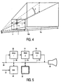
- Figure 4 shows this geometry in three-dimensional space.
- Far at left is the eye point of the camera position.
- the far clipping plane fcp at right and the near clipping plane ncp in the centre are perpendicular to the viewing axis, and together delimitate a viewing angle frustum.
- Similar clipping planes extend in the x- and y-directions.
- the signed distances top, bottom, left and right have been indicated. Further, the distances near and far between the origin and the projection plane and the object plane have been indicated. Also the height angle fi has been shown.
- Figure 5 shows a device for implementing the invention.
- the set-up is centred around communication bus 20 and main memory 30.
- the information to be processed is fetched from memory and sent to processing modules 22, 24, 26 that are connected in series to symbolize successive operations as will be listed in the tables hereinafter.
- the processing modules may be collectively mapped on shared hardware such as a CPU. After processing and possibly transient storage, the successive display frames attain subsystem 34 for display to a user.
- Overall control subsystem 28 is connected to the processing modules via control lines 23, 25, 27, that may lead via bus 20. In this manner, the data may in the CPU be translated into an image.
- Control subsystem 28 may receive control and data signals from various sources, such as manual or other inputs 32 from an actual user, external signals from other users in an interactive environment, or from cameras or further subsystems not shown for brevity.
- the complete frame content may change with time. If the geometrical relations between the previous camera position and direction and the new camera position and direction are known, the coherence between the pixels of the old source frame and the new intermediate display frame to be extrapolated will also be known. Table 1 gives various mathematical expressions, including relations between various coordinates, such as view space coordinates, projection coordinates, normalized device coordinates and screen-space coordinates.
- equation (1) is the perspective projection matrix. It defines the various quantities near, far, top, bottom, left and right plane positions of the viewing frustrum shown in Figure 4.
- Equations (2) define a Symmetrical Viewing Frustrum; an unsymmetrical frustrum may be used as well.
- equations (3) define the use of the height angle fi and aspect ratio a to further specify the viewing frustrum.
- Equation (4) expresses the relations between the projection coordinates (postscripted p ) and homogeneous view coordinates (postscripted v ) via the projection matrix P . Other projections such as orthogonal are also feasible.
- Equation (5) gives normalized device coordinates (subscripted n ).
- equation (6) gives the screen coordinates (postscripted s ).
- Equation (10) gives the coordinates in the extrapolated frame, so that the expressions for ( xs2, ys2 ) can be straightforwardly found as given in (11).
- (12) is the expression for zv2 .
- fz is linearly related to the screen coordinates xs1 and ys1 , and fz may be incrementally computed during scan conversion by adding a constant delta that is the time derivative of the movement.
- calculating zv requires the following:
- xs2 and ys2 can be written according to expression (13). Also, fx and fy are linearly related to the screen coordinates xs1 and ys1 , so that they may also be incrementally computed by adding a constant delta. Therefore, the incremental calculation of xs2 and ys2 requires the following, in addition to calculating zx2 :
- many game applications will present one or more objects on the screen, which may observe a dynamic behaviour that is independent from camera movement.
- This behaviour may be represented by a relative transform with respect to the camera for each such object that will usually be represented as one rigid body, or as a composite made up of various interconnected rigid bodies.
- Object movement can be realized by multiplying the camera transformation matrix M cam by the rigid-body transformation M obj for all pixels of the object in question.
- the displacement functions described earlier will calculate the motion vectors of the various pixels.
- an extra description plane which contains object or matrix pointers.
- the number of such rigid bodies in any scene will be less than 256, so one extra byte per pixel should be sufficient.
- the object plane can be efficiently compressed with runlength encoding RLE as usually the plane will contain large areas of uniform-valued pixels that belong to a single rigid body.
- xp , yp , zp , wp ⁇ P . ⁇ xv , yv , zv , 1 ;
- xn ⁇ yn ⁇ xp , yp ⁇ / wp ;
Landscapes
- Engineering & Computer Science (AREA)
- Multimedia (AREA)
- Signal Processing (AREA)
- Processing Or Creating Images (AREA)
- Image Processing (AREA)
- Controls And Circuits For Display Device (AREA)
- Television Systems (AREA)
- Liquid Crystal Display Device Control (AREA)
Claims (10)
- Verfahren zur Wiedergabe einer ersten Folge von Wiedergabebildern, wobei dieses Verfahren die nachfolgenden Verfahrensschritte umfasst:- das Empfangen einer zweiten Folge von Quellenbildern mit einer Quellenbildrate, und das Synthetisieren eines oder mehrerer zwischen liegender Bilder durch Anwendung eines geometrischen Transformationsverfahrens, und zwar auf Basis der genannten zweiten Folge für ein Paar unmittelbar aneinander grenzender Quellenbilder,dadurch gekennzeichnet, dass jedes zwischen liegendes Bild ausschließlich auf einem unmittelbar vorhergehenden Quellenbild basiert, durch Extrapolation von Kameratransformationen, und durch, auf Basis von Z-Pufferinformation, Im-Bild-Extrapolation unbedeckter tieferer Pixel von ähnlicherweise tiefer liegender aber zu dem betreffenden Zeitpunkt ständig sichtbarer derartiger tiefer liegender Pixel,- um, auf Basis einer Folge der genannten zwischen liegenden Bilder, und vielleicht auch auf Basis der genannten Quellenbilder, die genannten Wiedergabebilder mit einer höheren Wiedergabebildrate gegenüber der genannten Quellenbildrate zu selektieren.
- Verfahren nach Anspruch 1, um, unter Verwendung der bekannten Kamerabewegung gegenüber einem jüngsten Quellenbild, eine augenblickliche Kohärenz zwischen Pixeln dieses genannten Quellenbildes und Pixeln eines unmittelbar nachfolgenden synthetisierten Wiedergabebildes zu erzeugen.
- Verfahren nach Anspruch 1, und basiert auf Im-Bild-Extrapolation, die ausschließlich zusammen mit oder entgegen der Wiedergabe von Zeilenabtastbewegung arbeitet.
- Verfahren nach Anspruch 1, wobei weiterhin ein Festkörper in einem extrapolierten Bild entsprechend einer Transformationsmatrix M=Mcam*Mobj wiedergegeben wird.
- Verfahren nach Anspruch 1, wobei ein nicht bedecktes Item ignoriert wird, das sich auf ein nicht ständig sichtbares Pixel bezieht, bis zum Eintreffen eines nächsten Quellenbildes, das ein derartiges Item wie wiedergegeben hat.
- Bild-basierte Anordnung, vorgesehen zum Wiedergeben einer ersten Folge von Wiedergabebildern, wobei diese Anordnung die nachfolgenden Elemente umfasst:- Empfangsmittel zum Empfangen einer zweiten Folge von Quellenbildern mit einer Quellenbildrate, und Synthetisiermittel zum Synthetisieren eines oder mehrerer zwischen liegender Bilder durch Anwendung eines geometrischen Transformationsverfahrens, und zwar auf Basis der genannten zweiten Folge für ein Paar unmittelbar aneinander grenzender Quellenbilder,dadurch gekennzeichnet, dass die genannten Synthetisiermittel dazu vorgesehen sind um jedes zwischen liegende Bild ausschließlich auf einem unmittelbar vorhergehenden Quellenbild zu basieren, und zwar durch Extrapolation von Kameratransformationen, und durch, auf Basis von Z-Pufferinformation, Im-Bild-Extrapolation unbedeckter tieferer Pixel von ähnlicherweise tiefer liegender aber zu dem betreffenden Zeitpunkt ständig sichtbarer derartiger tiefer liegender Pixel,- und Auslieferungsmittel, um, gespeist durch die genannten Synthetisierungsmittel, auf Basis einer Folge der genannten zwischen liegenden Bilder, und vielleicht auch auf Basis der genannten Quellenbilder, die genannten Wiedergabebilder mit einer höheren Wiedergabebildrate gegenüber der genannten Quellenbildrate auszuliefern.
- Anordnung nach Anspruch 6, wobei die genannten Synthetisierungsmittel dazu vorgesehen sind, Kamerabewegungsinformation in Bezug auf ein jüngstes Quellenbild zu empfangen um eine augenblickliche Kohärenz zwischen Pixeln dieses genannten Quellenbildes und Pixeln eines unmittelbar nachfolgenden synthetisierten Wiedergabebildes zu erzeugen.
- Anordnung nach Anspruch 6, wobei die genannten Synthetisierungsmittel Im-Bild-Extrapolationsmittel aufweisen, die ausschließlich zusammen mit oder entgegen Wiedergabezeilenabtastbewegung arbeiten.
- Anordnung nach Anspruch 6, mit Matrixmultiplikationsmitteln zum Wiedergaben eines Festkörpers in einem extrapolierten Bild entsprechend einer Transformationsmatrix M=Mcam *Mobj.
- Anordnung nach Anspruch 6, mit Ignorierungsmitteln zum Ignorieren eines unbedeckten Items, das sich auf ein nicht ständig sichtbares Pixel bezieht, bis an das Eintreffen eines nächsten Quellenbildes, das ein derartiges Item wie wiedergegeben hat.
Priority Applications (1)
| Application Number | Priority Date | Filing Date | Title |
|---|---|---|---|
| EP99942625A EP0986906B1 (de) | 1998-04-01 | 1999-03-22 | Methode und verfahren zur erzeugung von einzelbildern aus einer sequenz von quellenbildern durch herstellung eines oder mehrerer direkt vor den quellenbildern sich befindlichen zwischenbildern |
Applications Claiming Priority (4)
| Application Number | Priority Date | Filing Date | Title |
|---|---|---|---|
| EP98201034 | 1998-04-01 | ||
| EP98201034 | 1998-04-01 | ||
| EP99942625A EP0986906B1 (de) | 1998-04-01 | 1999-03-22 | Methode und verfahren zur erzeugung von einzelbildern aus einer sequenz von quellenbildern durch herstellung eines oder mehrerer direkt vor den quellenbildern sich befindlichen zwischenbildern |
| PCT/IB1999/000486 WO1999051029A2 (en) | 1998-04-01 | 1999-03-22 | A method and device for generating display frames from a sequence of source frames through synthesizing one or more intermediate frames exclusively from an immediately preceding source frame |
Publications (2)
| Publication Number | Publication Date |
|---|---|
| EP0986906A2 EP0986906A2 (de) | 2000-03-22 |
| EP0986906B1 true EP0986906B1 (de) | 2007-05-09 |
Family
ID=8233549
Family Applications (1)
| Application Number | Title | Priority Date | Filing Date |
|---|---|---|---|
| EP99942625A Expired - Lifetime EP0986906B1 (de) | 1998-04-01 | 1999-03-22 | Methode und verfahren zur erzeugung von einzelbildern aus einer sequenz von quellenbildern durch herstellung eines oder mehrerer direkt vor den quellenbildern sich befindlichen zwischenbildern |
Country Status (8)
| Country | Link |
|---|---|
| US (1) | US6442303B1 (de) |
| EP (1) | EP0986906B1 (de) |
| JP (1) | JP4236705B2 (de) |
| KR (1) | KR100632195B1 (de) |
| CN (1) | CN1134983C (de) |
| DE (1) | DE69936029T2 (de) |
| TW (1) | TW401699B (de) |
| WO (1) | WO1999051029A2 (de) |
Families Citing this family (10)
| Publication number | Priority date | Publication date | Assignee | Title |
|---|---|---|---|---|
| GB0010685D0 (en) * | 2000-05-03 | 2000-06-28 | Koninkl Philips Electronics Nv | Autostereoscopic display driver |
| US7133566B2 (en) | 2000-12-20 | 2006-11-07 | Altera Corporation | Method of filling exposed areas in digital images |
| KR20030048303A (ko) * | 2001-12-12 | 2003-06-19 | 주식회사 하빈 | 주위환경 자동적응형 디지털 오디오 재생장치 |
| US8053528B2 (en) * | 2007-05-30 | 2011-11-08 | Georgia-Pacific Chemicals Llc | Binder compositions for fiber mats, and fiber mats and articles comprising them |
| KR101545510B1 (ko) | 2008-12-24 | 2015-08-20 | 삼성전자주식회사 | 프레임 속도 조절이 가능한 2차원 영상 또는 3차원 영상 디스플레이 방법 및 장치 |
| CN101867730B (zh) * | 2010-06-09 | 2011-11-16 | 马明 | 一种基于用户轨迹的多媒体合成方法 |
| CN103260044B (zh) * | 2013-05-10 | 2015-05-20 | 深圳创维-Rgb电子有限公司 | 3d超高清信号处理方法和装置 |
| JP6708407B2 (ja) * | 2015-12-25 | 2020-06-10 | キヤノン株式会社 | 画像処理装置、画像処理方法およびプログラム |
| DE102016221204A1 (de) * | 2016-10-27 | 2018-05-03 | Siemens Aktiengesellschaft | Bestimmung mindestens eines genäherten Zwischendatensatzes für eine Echtzeitanwendung |
| WO2020191147A1 (en) * | 2019-03-21 | 2020-09-24 | Ocelot Laboratories Llc | Frame rate extrapolation |
Family Cites Families (7)
| Publication number | Priority date | Publication date | Assignee | Title |
|---|---|---|---|---|
| DE3531677A1 (de) | 1985-09-05 | 1987-03-12 | Philips Patentverwaltung | Verfahren und anordnung zur erzeugung von zwischenbildsignalen aus referenzbildsignalen mit verringerter bildfrequenz |
| JPH04348692A (ja) * | 1991-05-27 | 1992-12-03 | Matsushita Electric Ind Co Ltd | ディジタルコンバーゼンス装置 |
| US5706417A (en) * | 1992-05-27 | 1998-01-06 | Massachusetts Institute Of Technology | Layered representation for image coding |
| DE69530824D1 (de) * | 1994-06-20 | 2003-06-26 | Sega Corp | Verfahren und gerät zur bildverarbeitung |
| US5604856A (en) * | 1994-10-13 | 1997-02-18 | Microsoft Corporation | Motion compensated noise reduction method and system for computer generated images |
| US5550543A (en) * | 1994-10-14 | 1996-08-27 | Lucent Technologies Inc. | Frame erasure or packet loss compensation method |
| EP0815538A1 (de) * | 1995-03-22 | 1998-01-07 | IDT INTERNATIONAL DIGITAL TECHNOLOGIES DEUTSCHLAND GmbH | Verfahren und gerät zur tiefenmodellierung und tiefeninformationenerzeugung von sich bewegenden objekten |
-
1998
- 1998-08-31 TW TW087114407A patent/TW401699B/zh not_active IP Right Cessation
-
1999
- 1999-03-22 KR KR1019997011234A patent/KR100632195B1/ko not_active IP Right Cessation
- 1999-03-22 DE DE69936029T patent/DE69936029T2/de not_active Expired - Lifetime
- 1999-03-22 CN CNB998008745A patent/CN1134983C/zh not_active Expired - Fee Related
- 1999-03-22 WO PCT/IB1999/000486 patent/WO1999051029A2/en active IP Right Grant
- 1999-03-22 EP EP99942625A patent/EP0986906B1/de not_active Expired - Lifetime
- 1999-03-22 JP JP54909999A patent/JP4236705B2/ja not_active Expired - Fee Related
- 1999-03-30 US US09/281,351 patent/US6442303B1/en not_active Expired - Fee Related
Also Published As
| Publication number | Publication date |
|---|---|
| EP0986906A2 (de) | 2000-03-22 |
| CN1134983C (zh) | 2004-01-14 |
| US6442303B1 (en) | 2002-08-27 |
| JP2002508146A (ja) | 2002-03-12 |
| KR20010013243A (ko) | 2001-02-26 |
| CN1273001A (zh) | 2000-11-08 |
| DE69936029D1 (de) | 2007-06-21 |
| DE69936029T2 (de) | 2008-01-10 |
| KR100632195B1 (ko) | 2006-10-11 |
| WO1999051029A2 (en) | 1999-10-07 |
| TW401699B (en) | 2000-08-11 |
| JP4236705B2 (ja) | 2009-03-11 |
| WO1999051029A3 (en) | 1999-12-16 |
Similar Documents
| Publication | Publication Date | Title |
|---|---|---|
| EP0221704B1 (de) | Videosignalverarbeitung | |
| US5077608A (en) | Video effects system able to intersect a 3-D image with a 2-D image | |
| US4667236A (en) | Television perspective effects system | |
| EP0638875B1 (de) | Verfahren und Gerät zur Erzeugung von dreidimensionaler Animation | |
| US7667699B2 (en) | Fast rendering of pyramid lens distorted raster images | |
| US20020094132A1 (en) | Method, apparatus and computer program product for generating perspective corrected data from warped information | |
| US20080309668A1 (en) | Image processing method and apparatus | |
| EP0986906B1 (de) | Methode und verfahren zur erzeugung von einzelbildern aus einer sequenz von quellenbildern durch herstellung eines oder mehrerer direkt vor den quellenbildern sich befindlichen zwischenbildern | |
| JPH04211584A (ja) | マッピング関数回路 | |
| JPH08315171A (ja) | アニメーションデータの作成方法および作成装置 | |
| Regan et al. | An interactive graphics display architecture | |
| KR100381817B1 (ko) | 제트버퍼를 이용한 입체영상 생성방법 및 기록매체 | |
| EP3573018B1 (de) | Bilderzeugungsvorrichtung und bildanzeigesteuerungsvorrichtung | |
| JP3083995B2 (ja) | 画像処理方法および装置 | |
| JP4099830B2 (ja) | 特殊効果装置、画像処理方法及び対象画像生成方法 | |
| JP2813881B2 (ja) | ビデオ信号処理装置 | |
| KR0166106B1 (ko) | 화상 처리 장치 및 그 방법 | |
| JP2737940B2 (ja) | 立体表現画像の陰影付加装置 | |
| Akka | Automatic software control of display parameters for stereoscopic graphics images | |
| JP2005011275A (ja) | 立体画像表示システム及び立体画像表示プログラム | |
| JPH07320088A (ja) | 画像生成装置 | |
| JP3311905B2 (ja) | 画像処理装置 | |
| Carrozzo et al. | Geometric transformations for displaying virtual objects on stereoscopic devices | |
| JPH04165473A (ja) | 二次元画像の変形装置 | |
| JP3014395B2 (ja) | 立体画像表示システム |
Legal Events
| Date | Code | Title | Description |
|---|---|---|---|
| PUAI | Public reference made under article 153(3) epc to a published international application that has entered the european phase |
Free format text: ORIGINAL CODE: 0009012 |
|
| AK | Designated contracting states |
Kind code of ref document: A2 Designated state(s): DE FR GB IT |
|
| 17P | Request for examination filed |
Effective date: 20000616 |
|
| GRAP | Despatch of communication of intention to grant a patent |
Free format text: ORIGINAL CODE: EPIDOSNIGR1 |
|
| GRAS | Grant fee paid |
Free format text: ORIGINAL CODE: EPIDOSNIGR3 |
|
| GRAA | (expected) grant |
Free format text: ORIGINAL CODE: 0009210 |
|
| AK | Designated contracting states |
Kind code of ref document: B1 Designated state(s): DE FR GB IT |
|
| REG | Reference to a national code |
Ref country code: GB Ref legal event code: FG4D |
|
| REF | Corresponds to: |
Ref document number: 69936029 Country of ref document: DE Date of ref document: 20070621 Kind code of ref document: P |
|
| ET | Fr: translation filed | ||
| PLBE | No opposition filed within time limit |
Free format text: ORIGINAL CODE: 0009261 |
|
| STAA | Information on the status of an ep patent application or granted ep patent |
Free format text: STATUS: NO OPPOSITION FILED WITHIN TIME LIMIT |
|
| 26N | No opposition filed |
Effective date: 20080212 |
|
| PG25 | Lapsed in a contracting state [announced via postgrant information from national office to epo] |
Ref country code: IT Free format text: LAPSE BECAUSE OF FAILURE TO SUBMIT A TRANSLATION OF THE DESCRIPTION OR TO PAY THE FEE WITHIN THE PRESCRIBED TIME-LIMIT Effective date: 20070509 |
|
| PGFP | Annual fee paid to national office [announced via postgrant information from national office to epo] |
Ref country code: GB Payment date: 20130328 Year of fee payment: 15 |
|
| PGFP | Annual fee paid to national office [announced via postgrant information from national office to epo] |
Ref country code: DE Payment date: 20130531 Year of fee payment: 15 |
|
| PGFP | Annual fee paid to national office [announced via postgrant information from national office to epo] |
Ref country code: FR Payment date: 20130422 Year of fee payment: 15 |
|
| REG | Reference to a national code |
Ref country code: DE Ref legal event code: R082 Ref document number: 69936029 Country of ref document: DE Representative=s name: VOLMER, GEORG, DIPL.-ING., DE |
|
| REG | Reference to a national code |
Ref country code: DE Ref legal event code: R082 Ref document number: 69936029 Country of ref document: DE Representative=s name: VOLMER, GEORG, DIPL.-ING., DE Effective date: 20140331 Ref country code: DE Ref legal event code: R081 Ref document number: 69936029 Country of ref document: DE Owner name: KONINKLIJKE PHILIPS N.V., NL Free format text: FORMER OWNER: KONINKLIJKE PHILIPS ELECTRONICS N.V., EINDHOVEN, NL Effective date: 20140331 |
|
| REG | Reference to a national code |
Ref country code: DE Ref legal event code: R119 Ref document number: 69936029 Country of ref document: DE |
|
| GBPC | Gb: european patent ceased through non-payment of renewal fee |
Effective date: 20140322 |
|
| REG | Reference to a national code |
Ref country code: FR Ref legal event code: ST Effective date: 20141128 |
|
| REG | Reference to a national code |
Ref country code: DE Ref legal event code: R119 Ref document number: 69936029 Country of ref document: DE Effective date: 20141001 |
|
| PG25 | Lapsed in a contracting state [announced via postgrant information from national office to epo] |
Ref country code: FR Free format text: LAPSE BECAUSE OF NON-PAYMENT OF DUE FEES Effective date: 20140331 Ref country code: DE Free format text: LAPSE BECAUSE OF NON-PAYMENT OF DUE FEES Effective date: 20141001 Ref country code: GB Free format text: LAPSE BECAUSE OF NON-PAYMENT OF DUE FEES Effective date: 20140322 |