EP0986207A2 - Transmission d'un sous-canal en emplyant un signal pilote - Google Patents
Transmission d'un sous-canal en emplyant un signal pilote Download PDFInfo
- Publication number
- EP0986207A2 EP0986207A2 EP99117442A EP99117442A EP0986207A2 EP 0986207 A2 EP0986207 A2 EP 0986207A2 EP 99117442 A EP99117442 A EP 99117442A EP 99117442 A EP99117442 A EP 99117442A EP 0986207 A2 EP0986207 A2 EP 0986207A2
- Authority
- EP
- European Patent Office
- Prior art keywords
- signal
- frequency
- data
- sub
- main
- Prior art date
- Legal status (The legal status is an assumption and is not a legal conclusion. Google has not performed a legal analysis and makes no representation as to the accuracy of the status listed.)
- Withdrawn
Links
Images


Classifications
-
- H—ELECTRICITY
- H04—ELECTRIC COMMUNICATION TECHNIQUE
- H04H—BROADCAST COMMUNICATION
- H04H20/00—Arrangements for broadcast or for distribution combined with broadcast
- H04H20/44—Arrangements characterised by circuits or components specially adapted for broadcast
-
- H—ELECTRICITY
- H04—ELECTRIC COMMUNICATION TECHNIQUE
- H04H—BROADCAST COMMUNICATION
- H04H20/00—Arrangements for broadcast or for distribution combined with broadcast
- H04H20/28—Arrangements for simultaneous broadcast of plural pieces of information
-
- H—ELECTRICITY
- H04—ELECTRIC COMMUNICATION TECHNIQUE
- H04L—TRANSMISSION OF DIGITAL INFORMATION, e.g. TELEGRAPHIC COMMUNICATION
- H04L5/00—Arrangements affording multiple use of the transmission path
- H04L5/02—Channels characterised by the type of signal
- H04L5/06—Channels characterised by the type of signal the signals being represented by different frequencies
Definitions
- the present invention relates to a data transmission system, a communication station and a data transmission method and more particularly, to a communication technology which is suitable when digital signal data is transmitted between communication stations located away from each other in the form of microwave.
- Data to be transmitted include television signals of digital and analog types and other types of information.
- a transmission side once performs baseband modulation over input data to obtain a signal subjected to the baseband modulation, and creates a signal Sit having an intermediate frequency from the baseband-modulated signal. And the transmission side eventually creates a signal Sht having a final radio frequency (RF) after subjected to an up-conversion, and transmits the radio-frequency signal Sht.
- RF radio frequency
- a receiver side converts a radio-frequency signal Shr received and amplified in a similar manner to in the transmission side to a frequency down-conversion to obtain a signal Sir having an intermediate frequency, and then subjects the signal Sir to a baseband demodulation.
- FIG. 7 An example of a transmission system having a prior art arrangement is shown in Fig. 7.
- a baseband modulator 1 converts main data (to be transmitted) received from a terminal 22 to the signal Sit of the intermediate frequency on the basis of a clock CK2 of a frequency f2 received from an oscillator (OSC) 9B.
- the frequency fit of the signal Sit is related to the frequency f2 of the clock CK2. In other words, an accuracy in the frequency fit of the signal Sit depends on an accuracy in the frequency f2 of the clock CK2.
- a frequency converter 3 converts with respect to frequency the signal Sit of the intermediate frequency fit to the signal Sht of the radio-frequency fht on the basis of a frequency f1 of a clock CK1 received from an oscillator (OSC) 9 as a reference frequency.
- OSC oscillator
- a power amplifier 4 amplifies the signal Sht to such an level that the signal Sht can have a predetermined transmission power, and transmits the power-amplified radio-frequency transmission signal from an antenna 5 toward an antenna 10 on the receiver side.
- a preamplifier 13 outputs a received signal as the radio-frequency-amplified signal Shr.
- a frequency converter 11 down-converts the signal Shr to the signal Sir of an intermediate frequency fir on the basis of a frequency f3 of a clock CK3 received from an oscillator (OSC) 9C as a reference frequency.
- OSC oscillator
- a frequency shift in the oscillator (OSC) 9C is related to a frequency shift in the signal Sir of the intermediate frequency.
- a baseband demodulator 12 demodulates the original main data from the signal Sir of the intermediate frequency on the basis of a frequency f4 of a clock CK4 received from oscillator (OSC) 9D as a reference frequency, and then outputs the demodulated data to a terminal 24.
- OSC oscillator
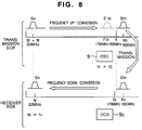
- the frequency conversion is carried out by multiplying the clock CK1 corresponding to the frequency difference f1 between the frequency fit and the reference frequency fht of the transmission side by the signal Sit.
- output signals having frequencies of 1.82 GHz and 1.78 GHz are obtained.
- one of the output signals having the frequency of 1.78 GHz is removed by a filter and only the signal of the frequency of 1.82 GHz is used as a transmission signal.
- the intermediate-frequency signal Sit is up-converted by the frequency converter 3 of the transmission side to the radio-frequency signal Sht and is down-converted by the frequency converter 11 of the receiver side to the intermediate-frequency signal Sir.
- a baseband modulating and demodulating system uses about 6,000 multicarriers having an interval of about 1 KHz.
- 1 KHz or more of accuracy lack, in particular, in the frequency conversion of the receiver side, this will involve great influence such as difficult normal demodulation.
- pilot signal interpolation system wherein some of multicarriers are used as frequency references in transmission and receiver sides.
- a technique for interpolating a pilot signal in an OFDM signal is disclosed in "Development of the OFDM Modem", Kisoda. et al., Technical Report of The Institute of Image Information and Television Engineers, August 26, 1997, pp. 13-18.
- the pilot signal interpolation system has its limit in synchronizable range.
- signals of an UHF band are frequency-converted to signals of a microwave band as a transmission band and converted again to signals of the UHF band in the receiver side, the frequency shift becomes great.
- the accuracy of the oscillator is defined by ppm.
- a frequency error between the transmission and receiver sides is 7 KHz for a transmission band of 7 GHz and is about 800 Hz for a transmission band of 800 MHz.
- the frequency error to be transmitted in broadcasting applications is restricted to an accurate range of several tens of Hz.
- the data transmission system has a problem that there must be provided a private line for maintenance contact or control signal which is to be used by a radio facility manager, in addition to the main data transmission line.
- transmission requests which include a digitized voice signal for contact between the transmission and receiver sides and control data for control of devices in the receiver or relay stations.
- control data for control of devices in the receiver or relay stations.
- a transmission side adds to a main signal a sub-signal having a frequency out of a frequency band of the main signal as frequency conversion information and transmits the composite signal including the sub-signal and the main signal, whereas, a receiver side extracts the added sub-signal from the received composite signal to make a frequency conversion reference for demodulation of the main signal coincide with that of the transmission side.
- the transmission side modulates the sub-signal to be added with sub-data and also transmits it, while the receiver side demodulates the sub-data.
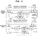
- a main signal Sit subjected to a baseband modulation is created based on a reference clock (for example, having a frequency f2 of 20 MHz obtained by frequency-dividing a signal having a frequency f1 of, e.g., 1,800 MHz from an oscillator (OSC) 9 by, e.g., 90) for the baseband modulation.
- a reference clock for example, having a frequency f2 of 20 MHz obtained by frequency-dividing a signal having a frequency f1 of, e.g., 1,800 MHz from an oscillator (OSC) 9 by, e.g., 90
- a pilot signal (sub-signal) Pt obtained by frequency-dividing the signal of the frequency f1 (of 1,800 MHz) from the OSC 9 by, e.g., 60.
- a signal Si&Pt having the added pilot signal Pt is up-converted to a signal Sh&Pt of a frequency of 1,820 and then transmitted.
- a receive signal Sh&Pr amplified in a receiver side is down-converted based on an output of a voltage-controlled oscillator (VCO) 15 into a signal Si&Pr.
- VCO voltage-controlled oscillator
- a pilot signal Pr is extracted from the signal Si&Pr, and compared with a result obtained by frequency-dividing the output of the VCO 15 by 60 to correct an frequency f1c of the output of the VCO 15.
- the frequency of the signal Si&Pt of the transmission side is also equal to the frequency of the signal Si&Pr of the receiver side.
- the pilot signal can be instantly discriminated from the main data modulated wave.
- Sub-data for modulation of the pilot signal Pt are considered to include digitized audio signal data for contact and control data for control of devices in signal receiver and relay stations.
- the modulation of the pilot signal with the sub-data can realize a transmission system which can transmit the sub-data while eliminating the need for provision of an additional channel exclusive to transmit the sub-data.
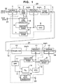
- Fig. 1 shows a block diagram of an entire arrangement of an embodiment of the data transmission system in accordance with the present invention, which will be detailed below.
- a transmitter basic section 20 similarly to Fig. 7, includes a baseband modulator 1, a frequency converter 3, a power amplifier 4, an antenna 5 and an oscillator (OSC) 9.
- the transmitter basic section 20 also includes a pilot signal adder 2, a pilot signal modulator 6, and frequency dividers 7 and 8 which form a featured part of the present invention.
- An output of the oscillator (OSC) 9 is connected to a terminal Lo of the frequency converter 3 and the frequency dividers 7 and 8.
- An output of the frequency divider 7 is sent to the pilot signal adder 2 via the pilot signal modulator 6 as a pilot signal Pt to be used as a reference of frequency conversion in the transmitter basic section 20.
- Sub-data received from a terminal 23 is applied to the pilot signal modulator 6.
- the sub-data are considered to include digitized voice signal data for contact between the transmission and receiver sides and control data for control of devices in signal receiver and relay stations.
- An output of the frequency divider 8 is applied to the baseband modulator 1 as a reference clock of the transmitter basic section 20.
- a receiver basic section 21 includes, similarly to Fig. 7, a preamplifier 13, a frequency converter 11 and a baseband demodulator 12.
- the receiver basic section 21 further include a pilot signal demodulator 18, frequency dividers 7 and 8, a phase locked loop (PLL) 14, a voltage-controlled oscillator (VCO) 15 and a bandpass filter (BPF) 17, which form a featured part of the present invention.
- PLL phase locked loop
- VCO voltage-controlled oscillator
- BPF bandpass filter
- An output of the VCO 15 is applied to the frequency dividers 7 and 8.
- An output of the frequency divider 7 is applied to the PLL 14.
- An output of the frequency converter 11 is applied to the baseband demodulator 12 and BPF 17.
- An output of the BPF 17 is applied to the other input of the PLL 14 and to the pilot signal demodulator 18.
- An output ⁇ of the PLL 14 is connected to a control terminal of the VCO 15.
- the frequency f2 (of, e.g., 20 MHz obtained by frequency-dividing the output (having the frequency f1 of, e.g., 1,800 MHz) of the OSC 9 by, e.g., 90) of the frequency divider 8 is used as a frequency reference in the baseband modulation.
- a modulated signal Sit having a frequency of 20 MHz is created by the baseband modulator 1.
- the output of the OSC 9 is frequency-divided by, e.g., 60 in the frequency divider 7 into a pilot signal Pt of a frequency of 30 MHz modulated with the sub-data.
- the pilot signal adder 2 adds together the signal Sit modulated with the main data and the pilot signal Pt modulated with the sub-data to generate a signal Si&Pt, and then outputs the signal Si&Pt.
- the frequency converter 3 up-converts the signal Si&Pt to a signal Sh&Pt having a radio frequency of, e.g., 1,820 MHz.
- the radio-frequency signal Sh&Pt is transmitted from the transmission side to the receiver side, and amplified by the preamplifier 13 of the receiver side to a signal Sh&Pr. And the signal Sh&Pr is frequency-converted by the frequency converter 11 to a signal Si&Pr having an intermediate frequency.
- the signal Si&Pr contains a component corresponding to the sender-side signal Sit of 20 MHz modulated with the main data and a component corresponding to the pilot signal Pr of 30 MHz modulated with the sub-data.
- the main data and sub-data subjected to the frequency conversion both do not have carrier frequencies of 20 MHz and 30 MHz respectively, thus generating a frequency shift corresponding to a difference between the frequencies f1 and f1c.
- the BPF 17 by utilizing the frequency difference, extracts the pilot signal Pr component of about 30 MHz from the composite signal Si&Pr of the intermediate frequency.
- the PLL 14 compares the frequency of the extracted pilot signal Pr component with a frequency obtained by dividing the output frequency of the VCO 15 by 60, and controls the frequency f1c of the VCO 15 in such a manner that the both frequencies become equal.
- the PLL 14 is controlled so that the oscillation frequency f1c of the VCO 15 decreases.
- the frequency of the pilot signal Pr in the transmission side becomes equal to that in the receiver side, so that the reference frequency of the frequency down-conversion of the receiver side is controlled to be equal to the reference frequency of the frequency up-conversion of the transmission side, thus generating no frequency shift between the transmission and receiver sides.
- the pilot signal Pr extracted by the BPF 17 is supplied to the pilot signal demodulator 18 where the sub-data is demodulated therefrom and then output to a terminal 25.
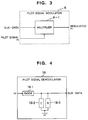
- the pilot signal modulator 6 Since the pilot signal is used as the frequency reference in the transmission side, the pilot signal modulator 6 is of a modulation type wherein a center of fluctuation frequencies of the pilot signal is fixed independently of contents of the sub-data.
- a simplest form of the modulation type is amplitude modulation.
- a multiplier 6-1 multiplies the sub-data by the pilot signal to generate a pilot signal Pt modulated with the sub-data, and outputs the pilot signal Pr.
- the pilot signal demodulator 18 is of a demodulation type associated with the modulation type used in the transmission side.
- the demodulation type is amplitude demodulation.
- the pilot signal Pr is sent via a diode 18-1 to a capacitor 18-2 and a resistor 18-3 to be accumulated therein and discharged therefrom, an envelope of the sub-data can be reproduced and the sub-data can be demodulated.
- a digitized voice signal for contact between the transmission and receiver sides as well as control data for control of devices in signal receiving and relay stations can be carried on the pilot signal as the sub-data, these signals can be transmitted while eliminating the need for provision of a private line or channel.
- FIG. 5 Another embodiment of the data transmission system in accordance with the present invention shown in Fig. 5 will be explained. This embodiment is arranged so that addition of the pilot signal in a transmission side is carried out after frequency up-conversion, while extraction of the pilot signal in a receiver side is carried out prior to frequency down-conversion.
- the outputs of the OSC's 9 and 15 can be directly used as the pilot signal and its comparison signal.
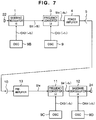
- Fig. 6 shows an arrangement of a radio relay system having a plurality of relay points, to which the data transmission system of the present invention is applied.
- a transmitter base section 20a located in a first point transmits a send signal having a frequency fh1
- a receiver base section 21a provided in a second point receives the signal of the frequency fh1 and converts it to a signal Si&Pr having an intermediate frequency.
- the pilot signal Pr having a frequency out of the frequency band is removed by a BPF 19 from the signal Si&Pr to leave only the signal Sir having a frequency within the band.
- the signal Sir is provided to a transmitter base section 20b and a frequency converter 30a.
- the transmitter base section 20b adds the pilot signal Pr modulated with the sub-data to the signal Sir, converts it to a send signal having a frequency fh2, and then transmits the converted signal toward a third point (a third communication station), similarly to the above.
- the signal Sir is converted to a signal having a UHF band frequency and power amplified by a UHF band amplifier 31, and only the main data subjected to the UHF band conversion is transmitted from an antenna 32 toward the periphery of the second point.
- UHF electromagnetic wave transmitted from the antenna 32 is received by the receivers of subscribers within a wave reach area.
- a received signal is frequency-converted by a receiver base section 21b to a signal Sir&Pr having an intermediate frequency, passed through a BPF 19 to obtain only the signal Sir, and then applied to a frequency converter 30b, similarly to the above.
- the signal Sir is converted by the frequency converter 30b to a signal having a UHF band frequency, power amplified by an UHF band amplifier 31, and then sent to a UHF band antenna 32 to transmit only the main data converted to the UHF band to the periphery of the second point.
- UHF electromagnetic wave transmitted from the antenna 32 is received by the receivers of subscribers within the wave reach area.
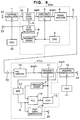
- Fig. 9 Shown in Fig. 9 is a block diagram of a further embodiment of the data transmission system in accordance with the present invention.
- the embodiment of Fig. 9 is basically the same as the embodiment of Fig. 1, except for the structures of the frequency divider and OSC.
- the same elements in Fig. 9 as those in Fig. 1 are denoted by the same reference numerals.
- a local oscillation signal for use in a baseband modulator 1 and a local oscillation signal for use in a frequency converter 3 are supplied from individual OSC's 40 and 9 respectively.
- the embodiment of Fig. 9 has no such a frequency divider 8 as used in the embodiment of Fig. 1.
- Reference symbol 20m denotes a transmitter basic section and symbol 21m denotes a receiver basic section.
- the transmitter and receiver basic sections 20m and 21m have basically the same functions as the transmitter and receiver basic sections 20 and 21.
- the baseband modulator 1 converts an input signal to a signal having an intermediate frequency Sit according to a clock generated by the OSC 40.
- the baseband demodulator 12 converts an input signal having the intermediate frequency Sit to a signal of a baseband according to a clock generated by an OSC 41.
- an error in the OSC's 40 and 41 remains in an output of a receiver side.
- the OSC's 40 and 41 generate the clocks having frequencies of several tens of MHz, even when the error is 1 ppm, a frequency difference therebetween is several Hz that is practically insignificant.
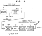
- FIG. 10 shows a block diagram of yet another embodiment of the data transmission system in accordance with the present invention.
- a communication station corresponding to the second point in the embodiment of Fig. 6 does not perform relay transmission to a third point.
- the communication station as a second point, after receiving a microwave signal from a first point (communication station), converts the received signal to a UHF electromagnetic wave signal and then transmits it to an associated subscriber.
- Fig. 10 shows an example of a studio-to-transmitter link (STL) of transmitting a signal in the form of microwave and then transmitting the signal having a UHF band frequency to general homes.
- the signal is passed through a BPF 19 to obtain only a main data component, frequency-converted by a frequency converter 30 to a signal having the UHF band frequency, amplified by a UHF band amplifier 31 to an output of a large to intermediate level, and then transmitted from an antenna 32 in the form of broadcasting wave.
- STL studio-to-transmitter link
- the pilot signal that is, the sub-signal modulated with the sub-data in the present invention may have a frequency that is higher or lower than the band of the main signal.
- the baseband modulator may employ a digital modulation system other than the OFDM modulation system or an analog modulation system.
- Data to be transmitted in the data transmission system of the present invention are considered to TV broadcasting signals or signals indicative of various media information other than the broadcasting signals.
- the signal transmission between the communication stations or between the communication and relay stations may be realized not only by the radio transmission but also by wired communication medium including an optical fiber cable.
- the frequency conversion reference of the transmission side can be made to coincide with that of the receiver side.
Applications Claiming Priority (2)
| Application Number | Priority Date | Filing Date | Title |
|---|---|---|---|
| JP25901698 | 1998-09-11 | ||
| JP10259016A JP2000092142A (ja) | 1998-09-11 | 1998-09-11 | データ伝送方式 |
Publications (2)
| Publication Number | Publication Date |
|---|---|
| EP0986207A2 true EP0986207A2 (fr) | 2000-03-15 |
| EP0986207A3 EP0986207A3 (fr) | 2003-09-24 |
Family
ID=17328188
Family Applications (1)
| Application Number | Title | Priority Date | Filing Date |
|---|---|---|---|
| EP99117442A Withdrawn EP0986207A3 (fr) | 1998-09-11 | 1999-09-08 | Transmission d'un sous-canal en emplyant un signal pilote |
Country Status (3)
| Country | Link |
|---|---|
| US (1) | US6813326B1 (fr) |
| EP (1) | EP0986207A3 (fr) |
| JP (1) | JP2000092142A (fr) |
Families Citing this family (10)
| Publication number | Priority date | Publication date | Assignee | Title |
|---|---|---|---|---|
| US6724804B1 (en) * | 1998-07-13 | 2004-04-20 | Kabushiki Kaisha Kobe Seiko Sho | Frequency converter and radio communications system employing the same |
| AU2001237988A1 (en) * | 2000-01-26 | 2001-08-07 | Vyyo, Ltd. | Transverter control mechanism for a wireless modem in a broadband wireless access system |
| US7359314B2 (en) * | 2001-12-26 | 2008-04-15 | Hitachi, Ltd. | Signal transmission system for transmitting a signal with a guard interval and a demodulation method thereof |
| JP4144622B2 (ja) | 2003-04-01 | 2008-09-03 | 日本電気株式会社 | 情報処理端末システム及びそれを用いた送受信方法 |
| KR20070006784A (ko) * | 2004-03-25 | 2007-01-11 | 마쓰시다 일렉트릭 인더스트리얼 컴패니 리미티드 | 무선 시스템 및 무선 통신 장치 |
| JP4560103B2 (ja) * | 2008-05-12 | 2010-10-13 | 株式会社東芝 | 中継装置 |
| JP2011259091A (ja) * | 2010-06-07 | 2011-12-22 | Sony Corp | 信号伝送システム、信号処理装置、基準信号送信装置、基準信号受信装置、電子機器、信号伝送方法 |
| JP4846864B2 (ja) * | 2010-06-14 | 2011-12-28 | 株式会社東芝 | 信号伝送装置及び信号伝送方法 |
| JP6080169B2 (ja) * | 2014-03-14 | 2017-02-15 | 古河電気工業株式会社 | 送受信システム、送信装置、および、受信装置 |
| JP5840283B1 (ja) * | 2014-12-18 | 2016-01-06 | 古河電気工業株式会社 | 受信装置 |
Citations (3)
| Publication number | Priority date | Publication date | Assignee | Title |
|---|---|---|---|---|
| US4837786A (en) * | 1986-08-07 | 1989-06-06 | Comstream Corporation | Technique for mitigating rain fading in a satellite communications system using quadrature phase shift keying |
| WO1997008861A1 (fr) * | 1995-08-25 | 1997-03-06 | Terayon Corporation | Dispositif et procede de transmission de donnees numeriques |
| US5796783A (en) * | 1995-10-31 | 1998-08-18 | Andre Alain Tabourian | Digital transmission system |
Family Cites Families (8)
| Publication number | Priority date | Publication date | Assignee | Title |
|---|---|---|---|---|
| JPS5636242A (en) | 1979-08-31 | 1981-04-09 | Nec Corp | Satellite communication system |
| US5408686A (en) * | 1991-02-19 | 1995-04-18 | Mankovitz; Roy J. | Apparatus and methods for music and lyrics broadcasting |
| US5339184A (en) * | 1992-06-15 | 1994-08-16 | Gte Laboratories Incorporated | Fiber optic antenna remoting for multi-sector cell sites |
| KR0165277B1 (ko) * | 1993-02-27 | 1999-03-20 | 김광호 | 디지탈신호 자기 기록 재생장치 |
| JP3390260B2 (ja) | 1994-08-09 | 2003-03-24 | 日本放送協会 | Ofdm変調信号復調用の基準搬送周波数を再生する方法および装置 |
| JP3145003B2 (ja) | 1995-03-23 | 2001-03-12 | 株式会社東芝 | 直交周波数分割多重伝送方式とその送信装置および受信装置 |
| JP3289610B2 (ja) * | 1996-07-31 | 2002-06-10 | 日本ビクター株式会社 | Ofdm復調装置及びその方法 |
| US5844939A (en) * | 1997-02-14 | 1998-12-01 | Hewlett-Packard Company | Low-cost phaselocked local oscillator for millimeter wave transceivers |
-
1998
- 1998-09-11 JP JP10259016A patent/JP2000092142A/ja active Pending
-
1999
- 1999-09-08 EP EP99117442A patent/EP0986207A3/fr not_active Withdrawn
- 1999-09-10 US US09/394,276 patent/US6813326B1/en not_active Expired - Fee Related
Patent Citations (3)
| Publication number | Priority date | Publication date | Assignee | Title |
|---|---|---|---|---|
| US4837786A (en) * | 1986-08-07 | 1989-06-06 | Comstream Corporation | Technique for mitigating rain fading in a satellite communications system using quadrature phase shift keying |
| WO1997008861A1 (fr) * | 1995-08-25 | 1997-03-06 | Terayon Corporation | Dispositif et procede de transmission de donnees numeriques |
| US5796783A (en) * | 1995-10-31 | 1998-08-18 | Andre Alain Tabourian | Digital transmission system |
Also Published As
| Publication number | Publication date |
|---|---|
| US6813326B1 (en) | 2004-11-02 |
| EP0986207A3 (fr) | 2003-09-24 |
| JP2000092142A (ja) | 2000-03-31 |
Similar Documents
| Publication | Publication Date | Title |
|---|---|---|
| JP4354530B2 (ja) | 加入者端末における周波数ドリフト補正 | |
| US4941150A (en) | Spread spectrum communication system | |
| US6377314B1 (en) | Methods and apparatus for transmitting analog and digital information signals | |
| US6823178B2 (en) | High-speed point-to-point modem-less microwave radio frequency link using direct frequency modulation | |
| US6973328B1 (en) | Millimeter wave band transmitter, millimeter wave band receiver and millimeter wave band communication apparatus carrying out radio communication in millimeter wave band region | |
| CN1143432A (zh) | 消除本振器相位噪声的调制技术 | |
| JP2000512813A6 (ja) | 加入者端末における周波数ドリフト補正 | |
| US4618996A (en) | Dual pilot phase lock loop for radio frequency transmission | |
| US6370361B1 (en) | Transceiver with a receive/transmit fast switch function | |
| US5953045A (en) | Channel selection type radio transmission apparatus | |
| US6813326B1 (en) | Data transmission system, data transmission communication station, and data transmission method | |
| CN100395958C (zh) | 使用零if进行再调制的方法及系统 | |
| US7177591B2 (en) | Frequency converter and radio communications system employing the same | |
| JP4160181B2 (ja) | 信号伝送方法及び中継装置 | |
| JP2005287065A (ja) | ミリ波帯通信装置 | |
| US5604746A (en) | Digital data receiver | |
| EP1168649A2 (fr) | Procedé et système de communication radio bidirectionelle | |
| US20070230970A1 (en) | Transmission Device, Reception Device, Signal Transmission Device, and Signal Transmission Method | |
| US6433830B1 (en) | Off-air phase lock technique | |
| US6917787B2 (en) | System and method for superheterodyne frequency multiplication signal expansion to achieve a reduced bandwidth frequency or phase modulation communication channel | |
| JPS61103324A (ja) | 無線通信装置のシンセサイザ回路 | |
| JP3745610B2 (ja) | ミリ波帯無線通信方法 | |
| KR100732885B1 (ko) | 갭 필러의 위상 잡음 감소장치 | |
| JP4560103B2 (ja) | 中継装置 | |
| JP2877197B2 (ja) | 非再生中継の警報伝送装置及び方法 |
Legal Events
| Date | Code | Title | Description |
|---|---|---|---|
| PUAI | Public reference made under article 153(3) epc to a published international application that has entered the european phase |
Free format text: ORIGINAL CODE: 0009012 |
|
| 17P | Request for examination filed |
Effective date: 19990908 |
|
| AK | Designated contracting states |
Kind code of ref document: A2 Designated state(s): AT BE CH CY DE DK ES FI FR GB GR IE IT LI LU MC NL PT SE |
|
| AX | Request for extension of the european patent |
Free format text: AL;LT;LV;MK;RO;SI |
|
| RIN1 | Information on inventor provided before grant (corrected) |
Inventor name: TSUKAMOTO, NOBUO Inventor name: NAKADA, TATSUHIRO Inventor name: TAKESUE, HIROYUKI Inventor name: ISHIDA, ITSUO Inventor name: KODA, HISAO Inventor name: SANO, SEEICHI Inventor name: AKIYAMA, TOSHIYUKI Inventor name: MIYASHITA, ATSUSHI |
|
| PUAL | Search report despatched |
Free format text: ORIGINAL CODE: 0009013 |
|
| AK | Designated contracting states |
Kind code of ref document: A3 Designated state(s): AT BE CH CY DE DK ES FI FR GB GR IE IT LI LU MC NL PT SE |
|
| AX | Request for extension of the european patent |
Extension state: AL LT LV MK RO SI |
|
| RIC1 | Information provided on ipc code assigned before grant |
Ipc: 7H 04L 27/00 B Ipc: 7H 04L 5/06 A |
|
| AKX | Designation fees paid |
Designated state(s): DE FR GB |
|
| STAA | Information on the status of an ep patent application or granted ep patent |
Free format text: STATUS: THE APPLICATION IS DEEMED TO BE WITHDRAWN |
|
| 18D | Application deemed to be withdrawn |
Effective date: 20060401 |