EP0985844B1 - Elektronisch gesteuerte Belüftung für eine Scheibenbremse - Google Patents
Elektronisch gesteuerte Belüftung für eine Scheibenbremse Download PDFInfo
- Publication number
- EP0985844B1 EP0985844B1 EP99113014A EP99113014A EP0985844B1 EP 0985844 B1 EP0985844 B1 EP 0985844B1 EP 99113014 A EP99113014 A EP 99113014A EP 99113014 A EP99113014 A EP 99113014A EP 0985844 B1 EP0985844 B1 EP 0985844B1
- Authority
- EP
- European Patent Office
- Prior art keywords
- electronically controlled
- disc brake
- ventilation
- disc
- flow
- Prior art date
- Legal status (The legal status is an assumption and is not a legal conclusion. Google has not performed a legal analysis and makes no representation as to the accuracy of the status listed.)
- Expired - Lifetime
Links
- 238000009423 ventilation Methods 0.000 title claims description 27
- 238000001816 cooling Methods 0.000 description 3
- 230000000694 effects Effects 0.000 description 3
- 230000002411 adverse Effects 0.000 description 1
- 230000001419 dependent effect Effects 0.000 description 1
- 238000006073 displacement reaction Methods 0.000 description 1
- 239000012530 fluid Substances 0.000 description 1
- 238000000034 method Methods 0.000 description 1
- 238000012544 monitoring process Methods 0.000 description 1
- 239000013585 weight reducing agent Substances 0.000 description 1
Images
Classifications
-
- B—PERFORMING OPERATIONS; TRANSPORTING
- B60—VEHICLES IN GENERAL
- B60B—VEHICLE WHEELS; CASTORS; AXLES FOR WHEELS OR CASTORS; INCREASING WHEEL ADHESION
- B60B7/00—Wheel cover discs, rings, or the like, for ornamenting, protecting, venting, or obscuring, wholly or in part, the wheel body, rim, hub, or tyre sidewall, e.g. wheel cover discs, wheel cover discs with cooling fins
- B60B7/0026—Wheel cover discs, rings, or the like, for ornamenting, protecting, venting, or obscuring, wholly or in part, the wheel body, rim, hub, or tyre sidewall, e.g. wheel cover discs, wheel cover discs with cooling fins characterised by the surface
- B60B7/0066—Wheel cover discs, rings, or the like, for ornamenting, protecting, venting, or obscuring, wholly or in part, the wheel body, rim, hub, or tyre sidewall, e.g. wheel cover discs, wheel cover discs with cooling fins characterised by the surface the dominant aspect being the surface structure
- B60B7/0086—Wheel cover discs, rings, or the like, for ornamenting, protecting, venting, or obscuring, wholly or in part, the wheel body, rim, hub, or tyre sidewall, e.g. wheel cover discs, wheel cover discs with cooling fins characterised by the surface the dominant aspect being the surface structure having cooling fins
-
- B—PERFORMING OPERATIONS; TRANSPORTING
- B60—VEHICLES IN GENERAL
- B60B—VEHICLE WHEELS; CASTORS; AXLES FOR WHEELS OR CASTORS; INCREASING WHEEL ADHESION
- B60B19/00—Wheels not otherwise provided for or having characteristics specified in one of the subgroups of this group
- B60B19/10—Wheels not otherwise provided for or having characteristics specified in one of the subgroups of this group with cooling fins
-
- F—MECHANICAL ENGINEERING; LIGHTING; HEATING; WEAPONS; BLASTING
- F16—ENGINEERING ELEMENTS AND UNITS; GENERAL MEASURES FOR PRODUCING AND MAINTAINING EFFECTIVE FUNCTIONING OF MACHINES OR INSTALLATIONS; THERMAL INSULATION IN GENERAL
- F16D—COUPLINGS FOR TRANSMITTING ROTATION; CLUTCHES; BRAKES
- F16D65/00—Parts or details
- F16D65/78—Features relating to cooling
- F16D65/84—Features relating to cooling for disc brakes
- F16D65/847—Features relating to cooling for disc brakes with open cooling system, e.g. cooled by air
-
- B—PERFORMING OPERATIONS; TRANSPORTING
- B60—VEHICLES IN GENERAL
- B60B—VEHICLE WHEELS; CASTORS; AXLES FOR WHEELS OR CASTORS; INCREASING WHEEL ADHESION
- B60B2900/00—Purpose of invention
- B60B2900/50—Improvement of
- B60B2900/513—Cooling, e.g. of brakes
-
- F—MECHANICAL ENGINEERING; LIGHTING; HEATING; WEAPONS; BLASTING
- F16—ENGINEERING ELEMENTS AND UNITS; GENERAL MEASURES FOR PRODUCING AND MAINTAINING EFFECTIVE FUNCTIONING OF MACHINES OR INSTALLATIONS; THERMAL INSULATION IN GENERAL
- F16D—COUPLINGS FOR TRANSMITTING ROTATION; CLUTCHES; BRAKES
- F16D65/00—Parts or details
- F16D65/78—Features relating to cooling
- F16D2065/783—Features relating to cooling cooling control or adjustment
Definitions
- the invention relates to an electronically controlled ventilation for a disc brake according to the preamble of claim 1 and is based on the generic GB 2 269 144 A.
- a brake release is known when using disc brakes.
- disc brakes because of the large contact pressures, locally high temperatures can occur, which have an adverse effect on the braking power.
- ventilation is provided for particularly highly stressed disc brakes.
- Most radially arranged air ducts are arranged in the brake discs, which are designed such that upon rotation, a fan effect arises. By this measure, one achieves lower temperatures during braking and after the braking process a faster cooling.
- the bore can also serve for rapid displacement of moisture during braking and weight reduction.
- the object of the invention is therefore to provide a ventilation for a disc brake according to the preamble of claim 1, which allows optimal braking in any driving condition and each brake load. This object is achieved by the features mentioned in the characterizing part of claim 1.
- a device for changing the flow cross-section is provided, which is acted on by a control unit.
- the control unit generates, depending on input variables, a ventilation signal corresponding to the desired change of the flow cross section.
- a simple embodiment variant is characterized in that a ventilation flap driven by a motor, in particular a torque motor or a geared motor, is provided as a device for changing the flow cross section in the flow channel.
- the ventilation flap releases the flow channel in the open state, closes it in the closed state and, by rotation, allows any intermediate position between the aforementioned extreme positions.
- the ventilation flap can be driven in a particularly simple manner by an electric motor, which is acted upon by the control unit. In particular, it should be ensured that the flow channel is open in the event of a system failure. This results in that the device is open when de-energized and can in a particular embodiment be achieved by a fault element which acts on the ventilation flap in an open state.
- the brake pad thickness, the brake pad temperature and / or the state of wear of the brake disc can be taken into account.
- other input parameters or sizes can be taken into account.
- These parameters can either be measured directly or calculated from the variables available in the vehicle.
- the aforementioned quantities can be placed on the CAN bus.
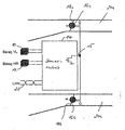
- the drawing represents a schematic sketch of an electronically controlled ventilation according to the invention.
- a control unit 14 which receives in the present case of analog sensors 10, 12 certain input values (pad VL, pad HR). In the present case, this is information about the top left and rear right. Based on this information and other information present on the CAN bus 22, the control unit 14 calculates the pad thickness, pad temperature, and wear state of the brake disk. From these input variables, a ventilation signal is generated by the control unit 14, which is applied via an output 15 to a line leading to two electric motors 16a and 16b and acts on them. The two motors 16a and 16b are arranged in respective ventilation channels 20a and 20b which are in fluid communication with brake discs (not shown) to be ventilated.
- the motors 16a and 16b are designed as a rotary actuator, in the present case as a torque motor (alternatively as a gear motor), wherein - schematically indicated - a helical return spring is arranged on each motor axis.
- a ventilation flap 18a, 18b is arranged, which can be opened, closed or maintained in an intermediate state by the operation of the motor. In the de-energized state (fail safe mode), the flap 18a, 18b is opened via the return spring.
- the "fail safe mode" can also be realized vice versa.
- the information about the current ventilation of the brake discs can also be placed on the CAN bus.
Landscapes
- Engineering & Computer Science (AREA)
- Mechanical Engineering (AREA)
- General Engineering & Computer Science (AREA)
- Braking Arrangements (AREA)
- Braking Systems And Boosters (AREA)
Description
- Die Erfindung betrifft eine elektronisch gesteuerte Belüftung für eine Scheibenbremse gemäß dem Oberbegriff des Anspruchs 1 und geht aus von der gattungsbildenden GB 2 269 144 A.
- Grundsätzlich ist bei der Verwendung von Scheibenbremsen eine Bremsbelüftung bekannt. Bei Scheibenbremsen können wegen der großen Anpreßkräfte örtlich hohe Temperaturen entstehen, die sich nachteilig auf das Bremsvermögen auswirken. Zur Vermeidung dieses Effekts ist bei besonders hoch beanspruchten Scheibenbremsen eine Belüftung vorgesehen. Meist sind in den Bremsscheiben radial angeordnete Luftkanäle angeordnet, die derart gestaltet sind, daß bei der Drehung eine Ventilatorwirkung entsteht. Durch diese Maßnahme erreicht man niedrigere Temperaturen beim Bremsen und nach dem Bremsvorgang eine schnellere Abkühlung. Die Bohrung kann ferner auch zum schnellen Verdrängen von Feuchtigkeit beim Bremsen und zur Gewichtserleichterung dienen.
- Es hat sich jedoch herausgestellt, daß eine optimale Bremswirkung nicht immer mit einer maximalen Belüftung einhergeht. Dies gilt auch dann, wenn vorgegeben werden kann, ob eine besonders intensive Bremsscheiben-Belüftung über einen Strömungskanal erfolgt, indem dieser zur Scheibenbremse führende Strömungskanal freigelegt wird, der unter anderen Betriebsbedingungen verschließbar ist. Eine solche sog. "Ein-Aus-Schaltung" einer Scheibenbremsen-Belüftung ist in der eingangs genannten GB 2 269 144 A gezeigt.
- Aufgabe der Erfindung ist es daher, eine Belüftung für eine Scheibenbremse nach dem Oberbegriff des Anspruchs 1 anzugeben, die in jedem Fahrzustand und bei jeder Bremsenbelastung eine optimale Bremsung ermöglicht. Diese Aufgabe wird durch die im kennzeichnenden Teil von Anspruch 1 genannten Merkmale gelöst.
- Demgemäß ist bei einer belüfteten Scheibenbremse im Verlauf eines zur Scheibenbremse hinführenden Strömungskanals eine Einrichtung zur Veränderung des Strömungsquerschnitts vorgesehen, welche von einer Steuereinheit beaufschlagt wird. Die Steuereinheit generiert in Abhängigkeit von Eingangsgrößen ein der gewünschten Veränderung des Strömungsquerschnittes entsprechendes Belüftungssignal.
- Durch die Veränderung des Strömungsquerschnitts in dem zur Bremsscheibe verlaufenden Strömungskanal kann eine auf den jeweiligen Fahrzustand und auf die jeweilige Bremsenbelastung angepaßte Kühlung sichergestellt werden.
- Eine einfache Ausführungsvariante ist dadurch gekennzeichnet, daß als Einrichtung zur Veränderung des Strömungsquerschnitts im Strömungskanal eine von einem Motor, insbesondere einem Torque-Motor oder einem Getriebemotor, angetriebene Belüftungsklappe vorgesehen ist. Die Belüftungsklappe gibt im offenen Zustand den Strömungskanal frei, verschließt ihn im geschlossenen Zustand und ermöglicht durch Drehung jede Zwischenstellung zwischen den vorgenannten Extremstellungen.
- Die Belüftungsklappe kann in besonders einfacher Weise von einem Elektromotor angetrieben werden, der von der Steuereinheit beaufschlagt wird. Insbesondere sollte sichergestellt werden, daß der Strömungskanal bei einem Systemausfall offen ist. Dies führt dazu, daß die Einrichtung im stromlosen Zustand geöffnet ist und kann in einer besonderen Ausführungsvariante durch ein Fehlerelement erreicht werden, welches die Belüftungsklappe in einem offenen Zustand beaufschlagt.
- Als Eingangsparameter können die Bremsbelag-Dicke, die Bremsbelag-Temperatur und/oder der Verschleißzustand der Bremsscheibe berücksichtigt werden. Alternativ können natürlich auch andere Eingangsparameter oder -größen berücksichtigt werden. Diese Parameter können entweder direkt gemessen oder aber aus den im Fahrzeug vorliegenden Größen berechnet werden. Zusätzlich können die vorgenannten Größen auf den CAN-Bus gelegt werden.
- Die vorliegende Erfindung wird anhand eines Ausführungsbeispiels mit Bezug auf die beiliegende Zeichnung näher erläutert. Die Zeichnung stellt eine schematische Skizze einer erfindungsgemäßen elektronisch gesteuerten Belüftung dar.
- Dabei ist eine Steuereinheit 14 vorgesehen, welche im vorliegenden Fall von Analogsensoren 10, 12 bestimmte Eingangswerte (Belag VL, Belag HR) erhält. Im vorliegenden Fall ist dies eine Information über den Belag vorne links und hinten rechts. Aufgrund dieser Informationen und anderer auf dem CAN-Bus 22 anliegender Informationen berechnet die Steuereinheit 14 die Belag-Dicke, die Belag-Temperatur und den Verschleißzustand der Bremsscheibe. Aus diesen Eingangsgrößen wird von der Steuereinheit 14 ein Belüftungssignal generiert, welches über einen Ausgang 15 an eine zu zwei Elektromotoren 16a und 16b führende Leitung angelegt wird und diese beaufschlagt. Die beiden Motoren 16a und 16b sind in entsprechenden Lüftungskanälen 20a und 20b angeordnet, die in Strömungsverbindung mit zu belüftenden Bremsscheiben (nicht dargestellt) stehen. Die Motoren 16a und 16b sind als Drehaktuator, im vorliegenden Fall als Torque-Motor (alternativ als Getriebemotor) ausgeführt, wobei - schematisch angedeutet - eine spiralförmige Rückholfeder auf jeder Motorachse angeordnet ist. Auf der Motorachse ist ferner eine Belüftungsklappe 18a, 18b angeordnet, die durch den Betrieb des Motors geöffnet, geschlossen oder in einem Zwischenzustand gehalten werden kann. Im stromlosen Zustand (fail safe mode) wird die Klappe 18a, 18b über die Rückholfeder geöffnet.
- Falls es für andere Anwendungen erforderlich ist, kann der "fail safe mode" auch umgekehrt realisiert werden. Die Information über die momentane Belüftung der Bremsscheiben kann auch auf den CAN-Bus gelegt werden.
- Durch eine Aktivstromüberwachung der Ansteuerschaltung können elektrische Unterbrechungen, beispielsweise im Stecker, im Kabel, in der Spule etc. erkannt werden.
- Insgesamt läßt sich mit der vorliegenden Erfindung eine kostengünstige Belüftungssteuerung zur parameterabhängigen Belüftung von Bremsscheiben realisieren. Dabei wird den Bremsscheiben eine für die optimale Funktionsweise der Bremsen erforderliche Kühlung zugeführt.
Claims (5)
- Elektronisch gesteuerte Belüftung für eine Scheibenbremse, insbesondere bei einem Fahrzeug, bei der eine zu belüftende Bremsscheibe im Verlauf eines Strömungskanals (20a, 20b) angeordnet ist, sowie mit einer Steuereinheit (14), die in Abhängigkeit von Eingangsgrößen (10, 12) ein Belüftungssignal erzeugt und dieses an eine Einrichtung (16a, 16b, 18a, 18b) zur Veränderung des Strömungsquerschnitts des Strömungskanals (20a, 20b) abgibt,
dadurch gekennzeichnet, dass der Strömungsquerschnitt des Strömungskanals nicht nur vollständig freigegeben oder verschlossen werden kann, sondern dass zwischen diesen beiden Extremen auch Zwischenstellungen des Strömungsquerschnitts einstellbar sind. - Elektronisch gesteuerte Belüftung für eine Scheibenbremse nach Anspruch 1,
dadurch gekennzeichnet,
daß als Einrichtung zur Veränderung des Strömungsquerschnitts im Strömungskanal eine von einem Motor (16a, 16b), insbesondere einem Torque-Motor oder Getriebe-Motor, angetriebene Belüftungsklappe (18a, 18b) vorgesehen ist. - Elektronisch gesteuerte Belüftung für eine Scheibenbremse nach Anspruch 1 oder 2,
dadurch gekennzeichnet,
daß die Einrichtung in einem stromlosen Zustand offen, insbesondere von einem Federelement offen gehalten ist. - Elektronisch gesteuerte Belüftung für eine Scheibenbremse nach einem der vorhergehenden Ansprüche,
dadurch gekennzeichnet,
daß als Eingangsgrößen die Bremsbelag-Dicke, die Bremsbelag-Temperatur und/oder der Verschleißzustand der Bremsscheibe berücksichtigt werden. - Elektronisch gesteuerte Belüftung für eine Scheibenbremse nach einem der vorhergehenden Ansprüche,
dadurch gekennzeichnet,
daß die Eingangsparameter direkt gemessen oder aus anderen im Fahrzeug vorliegenden Größen berechnet werden.
Applications Claiming Priority (2)
| Application Number | Priority Date | Filing Date | Title |
|---|---|---|---|
| DE19838116 | 1998-08-21 | ||
| DE19838116A DE19838116A1 (de) | 1998-08-21 | 1998-08-21 | Elektronisch gesteuerte Belüftung für eine Scheibenbremse |
Publications (3)
| Publication Number | Publication Date |
|---|---|
| EP0985844A2 EP0985844A2 (de) | 2000-03-15 |
| EP0985844A3 EP0985844A3 (de) | 2001-08-22 |
| EP0985844B1 true EP0985844B1 (de) | 2006-01-04 |
Family
ID=7878346
Family Applications (1)
| Application Number | Title | Priority Date | Filing Date |
|---|---|---|---|
| EP99113014A Expired - Lifetime EP0985844B1 (de) | 1998-08-21 | 1999-07-06 | Elektronisch gesteuerte Belüftung für eine Scheibenbremse |
Country Status (5)
| Country | Link |
|---|---|
| US (1) | US6318510B1 (de) |
| EP (1) | EP0985844B1 (de) |
| JP (1) | JP4399058B2 (de) |
| DE (2) | DE19838116A1 (de) |
| ES (1) | ES2255205T3 (de) |
Families Citing this family (7)
| Publication number | Priority date | Publication date | Assignee | Title |
|---|---|---|---|---|
| CN101903222B (zh) * | 2007-12-20 | 2014-07-23 | 沃尔沃拉斯特瓦格纳公司 | 用于保证制动组件的功能性的方法和车辆系统以及包括该系统的车辆 |
| DE102008007690A1 (de) * | 2008-02-06 | 2009-08-13 | GM Global Technology Operations, Inc., Detroit | Felge oder Radanbauteil für ein Kraftfahrzeugrad mit verschließbaren Öffnungen |
| DE102009014967B4 (de) | 2009-03-18 | 2017-11-02 | Dr. Ing. H.C. F. Porsche Aktiengesellschaft | Fahrzeug mit einem Rohluftkanal |
| DE102010015319A1 (de) * | 2010-04-17 | 2011-10-20 | Audi Ag | Felge für ein Fahrzeugrad |
| DE102010034417A1 (de) * | 2010-08-16 | 2012-02-16 | Audi Ag | Fahrzeugrad |
| DE102012017600A1 (de) * | 2012-09-06 | 2014-03-06 | Volkswagen Aktiengesellschaft | Verfahren zum Betreiben einer Stelleinrichtung zum Kühlen wenigstens einer Radbremse eines Kraftwagens sowie Kraftwagen |
| CN106379292A (zh) * | 2016-09-23 | 2017-02-08 | 苏州雷姆斯汽车工程有限公司 | 一种引流降温的刹车降温装置 |
Family Cites Families (16)
| Publication number | Priority date | Publication date | Assignee | Title |
|---|---|---|---|---|
| US3366203A (en) * | 1966-12-02 | 1968-01-30 | Budd Co | Controlled ventilation for disc brakes |
| US3491856A (en) * | 1968-09-30 | 1970-01-27 | Budd Co | Ventilated disk brake apparatus |
| SU895758A1 (ru) * | 1978-10-23 | 1982-01-07 | Белорусский Ордена Трудового Красного Знамени Политехнический Институт | Устройство управлени системой воздушного охлаждени тормозных механизмов транспортного средства |
| JPS63266229A (ja) * | 1987-04-22 | 1988-11-02 | Nippon Denso Co Ltd | 制動装置のモニタリング装置 |
| DE3813972A1 (de) * | 1987-05-08 | 1988-11-17 | Volkswagen Ag | Bremsenkuehlvorrichtung |
| DE3816415A1 (de) * | 1988-05-13 | 1989-11-16 | Bayerische Motoren Werke Ag | Fahrzeugbremse mit einer luftzufuhreinrichtung |
| DE3834119A1 (de) * | 1988-10-07 | 1990-04-12 | Peter Kirschner | Bremskuehlklappen- und luftfuehrungs- system fuer fahrzeuge |
| JPH03125656A (ja) * | 1989-10-11 | 1991-05-29 | Toyota Autom Loom Works Ltd | ブレーキの冷却装置 |
| US5121818A (en) * | 1991-05-02 | 1992-06-16 | Mccomic Richard D | Solar powered cooling apparatus for a vehicle brake system |
| DE4138464A1 (de) * | 1991-11-22 | 1993-06-03 | Knorr Bremse Ag | Fahrzeug mit luftgekuehlten reibungsbremsen und aufgeladenem brennkraftmotor |
| US5317880A (en) * | 1992-04-20 | 1994-06-07 | Spears Dan E | Auxiliary braking and cooling device |
| GB9215966D0 (en) * | 1992-07-28 | 1992-09-09 | Mclaren Cars Nv | Improvements in or relating to vehicle brake temperature control |
| DE4229945B4 (de) * | 1992-09-08 | 2007-01-04 | Audi Ag | Kraftfahrzeug |
| DE4243988A1 (de) * | 1992-12-23 | 1994-06-30 | Bayerische Motoren Werke Ag | Luftzufuhreinrichtung für die Fahrzeugbremse eines Kraftfahrzeugs |
| DE4420068A1 (de) * | 1994-06-08 | 1995-12-14 | Bayerische Motoren Werke Ag | Kühlluftzuführung für die Radbremsen eines Kraftfahrzeuges |
| JP3125656B2 (ja) | 1995-11-13 | 2001-01-22 | ブラザー工業株式会社 | 通信装置 |
-
1998
- 1998-08-21 DE DE19838116A patent/DE19838116A1/de not_active Withdrawn
-
1999
- 1999-07-06 ES ES99113014T patent/ES2255205T3/es not_active Expired - Lifetime
- 1999-07-06 EP EP99113014A patent/EP0985844B1/de not_active Expired - Lifetime
- 1999-07-06 DE DE59913008T patent/DE59913008D1/de not_active Expired - Lifetime
- 1999-08-20 JP JP23409199A patent/JP4399058B2/ja not_active Expired - Fee Related
- 1999-08-23 US US09/382,192 patent/US6318510B1/en not_active Expired - Lifetime
Also Published As
| Publication number | Publication date |
|---|---|
| US6318510B1 (en) | 2001-11-20 |
| ES2255205T3 (es) | 2006-06-16 |
| DE19838116A1 (de) | 2000-02-24 |
| JP4399058B2 (ja) | 2010-01-13 |
| DE59913008D1 (de) | 2006-03-30 |
| EP0985844A2 (de) | 2000-03-15 |
| EP0985844A3 (de) | 2001-08-22 |
| JP2000065106A (ja) | 2000-03-03 |
Similar Documents
| Publication | Publication Date | Title |
|---|---|---|
| EP1697186B1 (de) | Feststellbremse und verfahren zur steuerung derselben | |
| DE3410006C2 (de) | ||
| DE10142304B4 (de) | Steuervorrichtung und Steuerverfahren für eine Fahrzeugbremse | |
| DE68915292T2 (de) | Servolenkeinrichtung mit Motor. | |
| EP2880331B1 (de) | Verfahren zum steuern einer elektrischen belagverschleissnachstellvorrichtung für eine scheibenbremsenanordnung und scheibenbremse | |
| DE19910048A1 (de) | Verfahren und Vorrichtung zur Überwachung der Bewegung eines Aktuators | |
| EP1125067A1 (de) | Verfahren und vorrichtung zur überwachung der bewegung eines aktuators | |
| EP0985844A2 (de) | Elektronisch gesteuerte Belüftung für eine Scheibenbremse | |
| DE3421387C2 (de) | ||
| EP4426594B1 (de) | Verfahren zur elektronischen lüftspielregelung einer fahrzeugradbremse und elektronisches kraftfahrzeugbremssystem dazu | |
| EP1832776A2 (de) | Verfahren und Vorrichtung zum Steuern und/oder Regeln einer automatisierten Kupplung | |
| EP1572513A1 (de) | Bremssystem und verfahren zum betrieb eines bremsystems für elektrisch angetriebene fahrzeuge | |
| DE3013222C2 (de) | Automatische Fahr-Bremssteuerung | |
| DE10212612B4 (de) | Elektrisch betätigbare Fahrzeugbremse | |
| EP1687546B1 (de) | Drehmomenten bertragungseinrichtung | |
| DE10257839A1 (de) | Überwachung von Radbremsen | |
| EP0863604A1 (de) | Steuer- und/oder Regelvorrichtung bzw. -verfahren für einen Retarder als Zusatzbremseinrichtung für Fahrzeuge o. dgl. | |
| EP4357207B1 (de) | Einstellverfahren von betriebsbremsfunktionen für mobile arbeitsmaschinen sowie eine bremsanordnung | |
| DE602004005077T2 (de) | Getriebeüberwachungsmodul | |
| DE102024206710A1 (de) | Verfahren zum Betreiben einer elektromechanischen Betriebsbremse als Parkbremse | |
| DE19934496B4 (de) | Bremssystem für ein Flurförderzeug | |
| EP1881908B1 (de) | Steuerung der drehmomentübertragung in einem differenzial | |
| DE102004009980A1 (de) | Steuergerät zur Ansteuerung von Funktionseinheiten eines Kraftfahrzeugs und Verfahren zum Betreiben | |
| WO2025082876A1 (de) | Elektromechanische bremsvorrichtung für ein kraftfahrzeug | |
| DE102005022243A1 (de) | Drehmomentenübertragungseinrichtung |
Legal Events
| Date | Code | Title | Description |
|---|---|---|---|
| PUAI | Public reference made under article 153(3) epc to a published international application that has entered the european phase |
Free format text: ORIGINAL CODE: 0009012 |
|
| AK | Designated contracting states |
Kind code of ref document: A2 Designated state(s): AT BE CH CY DE DK ES FI FR GB GR IE IT LI LU MC NL PT SE |
|
| AX | Request for extension of the european patent |
Free format text: AL;LT;LV;MK;RO;SI |
|
| PUAL | Search report despatched |
Free format text: ORIGINAL CODE: 0009013 |
|
| AK | Designated contracting states |
Kind code of ref document: A3 Designated state(s): AT BE CH CY DE DK ES FI FR GB GR IE IT LI LU MC NL PT SE |
|
| AX | Request for extension of the european patent |
Free format text: AL;LT;LV;MK;RO;SI |
|
| 17P | Request for examination filed |
Effective date: 20020201 |
|
| AKX | Designation fees paid |
Free format text: DE ES FR GB IT SE |
|
| GRAP | Despatch of communication of intention to grant a patent |
Free format text: ORIGINAL CODE: EPIDOSNIGR1 |
|
| GRAS | Grant fee paid |
Free format text: ORIGINAL CODE: EPIDOSNIGR3 |
|
| GRAA | (expected) grant |
Free format text: ORIGINAL CODE: 0009210 |
|
| AK | Designated contracting states |
Kind code of ref document: B1 Designated state(s): DE ES FR GB IT SE |
|
| REG | Reference to a national code |
Ref country code: GB Ref legal event code: FG4D Free format text: NOT ENGLISH |
|
| GBT | Gb: translation of ep patent filed (gb section 77(6)(a)/1977) |
Effective date: 20060104 |
|
| REF | Corresponds to: |
Ref document number: 59913008 Country of ref document: DE Date of ref document: 20060330 Kind code of ref document: P |
|
| REG | Reference to a national code |
Ref country code: SE Ref legal event code: TRGR |
|
| REG | Reference to a national code |
Ref country code: ES Ref legal event code: FG2A Ref document number: 2255205 Country of ref document: ES Kind code of ref document: T3 |
|
| ET | Fr: translation filed | ||
| PLBE | No opposition filed within time limit |
Free format text: ORIGINAL CODE: 0009261 |
|
| STAA | Information on the status of an ep patent application or granted ep patent |
Free format text: STATUS: NO OPPOSITION FILED WITHIN TIME LIMIT |
|
| 26N | No opposition filed |
Effective date: 20061005 |
|
| PGFP | Annual fee paid to national office [announced via postgrant information from national office to epo] |
Ref country code: ES Payment date: 20110617 Year of fee payment: 13 |
|
| PGFP | Annual fee paid to national office [announced via postgrant information from national office to epo] |
Ref country code: SE Payment date: 20110722 Year of fee payment: 13 Ref country code: GB Payment date: 20110726 Year of fee payment: 13 Ref country code: FR Payment date: 20110816 Year of fee payment: 13 |
|
| PGFP | Annual fee paid to national office [announced via postgrant information from national office to epo] |
Ref country code: IT Payment date: 20110728 Year of fee payment: 13 |
|
| REG | Reference to a national code |
Ref country code: SE Ref legal event code: EUG |
|
| GBPC | Gb: european patent ceased through non-payment of renewal fee |
Effective date: 20120706 |
|
| REG | Reference to a national code |
Ref country code: FR Ref legal event code: ST Effective date: 20130329 |
|
| PG25 | Lapsed in a contracting state [announced via postgrant information from national office to epo] |
Ref country code: FR Free format text: LAPSE BECAUSE OF NON-PAYMENT OF DUE FEES Effective date: 20120731 Ref country code: GB Free format text: LAPSE BECAUSE OF NON-PAYMENT OF DUE FEES Effective date: 20120706 Ref country code: SE Free format text: LAPSE BECAUSE OF NON-PAYMENT OF DUE FEES Effective date: 20120707 |
|
| PG25 | Lapsed in a contracting state [announced via postgrant information from national office to epo] |
Ref country code: IT Free format text: LAPSE BECAUSE OF NON-PAYMENT OF DUE FEES Effective date: 20120706 |
|
| REG | Reference to a national code |
Ref country code: ES Ref legal event code: FD2A Effective date: 20131018 |
|
| PG25 | Lapsed in a contracting state [announced via postgrant information from national office to epo] |
Ref country code: ES Free format text: LAPSE BECAUSE OF NON-PAYMENT OF DUE FEES Effective date: 20120707 |
|
| PGFP | Annual fee paid to national office [announced via postgrant information from national office to epo] |
Ref country code: DE Payment date: 20160726 Year of fee payment: 18 |
|
| REG | Reference to a national code |
Ref country code: DE Ref legal event code: R119 Ref document number: 59913008 Country of ref document: DE |
|
| PG25 | Lapsed in a contracting state [announced via postgrant information from national office to epo] |
Ref country code: DE Free format text: LAPSE BECAUSE OF NON-PAYMENT OF DUE FEES Effective date: 20180201 |