EP0985801A2 - Blade configuration for steam turbine - Google Patents
Blade configuration for steam turbine Download PDFInfo
- Publication number
- EP0985801A2 EP0985801A2 EP99114881A EP99114881A EP0985801A2 EP 0985801 A2 EP0985801 A2 EP 0985801A2 EP 99114881 A EP99114881 A EP 99114881A EP 99114881 A EP99114881 A EP 99114881A EP 0985801 A2 EP0985801 A2 EP 0985801A2
- Authority
- EP
- European Patent Office
- Prior art keywords
- blade
- turbine
- turbine moving
- blades
- throat
- Prior art date
- Legal status (The legal status is an assumption and is not a legal conclusion. Google has not performed a legal analysis and makes no representation as to the accuracy of the status listed.)
- Granted
Links
Images


Classifications
-
- F—MECHANICAL ENGINEERING; LIGHTING; HEATING; WEAPONS; BLASTING
- F01—MACHINES OR ENGINES IN GENERAL; ENGINE PLANTS IN GENERAL; STEAM ENGINES
- F01D—NON-POSITIVE DISPLACEMENT MACHINES OR ENGINES, e.g. STEAM TURBINES
- F01D5/00—Blades; Blade-carrying members; Heating, heat-insulating, cooling or antivibration means on the blades or the members
- F01D5/12—Blades
- F01D5/26—Antivibration means not restricted to blade form or construction or to blade-to-blade connections or to the use of particular materials
-
- F—MECHANICAL ENGINEERING; LIGHTING; HEATING; WEAPONS; BLASTING
- F01—MACHINES OR ENGINES IN GENERAL; ENGINE PLANTS IN GENERAL; STEAM ENGINES
- F01D—NON-POSITIVE DISPLACEMENT MACHINES OR ENGINES, e.g. STEAM TURBINES
- F01D5/00—Blades; Blade-carrying members; Heating, heat-insulating, cooling or antivibration means on the blades or the members
- F01D5/12—Blades
- F01D5/22—Blade-to-blade connections, e.g. for damping vibrations
- F01D5/24—Blade-to-blade connections, e.g. for damping vibrations using wire or the like
-
- F—MECHANICAL ENGINEERING; LIGHTING; HEATING; WEAPONS; BLASTING
- F01—MACHINES OR ENGINES IN GENERAL; ENGINE PLANTS IN GENERAL; STEAM ENGINES
- F01D—NON-POSITIVE DISPLACEMENT MACHINES OR ENGINES, e.g. STEAM TURBINES
- F01D5/00—Blades; Blade-carrying members; Heating, heat-insulating, cooling or antivibration means on the blades or the members
- F01D5/12—Blades
- F01D5/14—Form or construction
- F01D5/141—Shape, i.e. outer, aerodynamic form
-
- Y—GENERAL TAGGING OF NEW TECHNOLOGICAL DEVELOPMENTS; GENERAL TAGGING OF CROSS-SECTIONAL TECHNOLOGIES SPANNING OVER SEVERAL SECTIONS OF THE IPC; TECHNICAL SUBJECTS COVERED BY FORMER USPC CROSS-REFERENCE ART COLLECTIONS [XRACs] AND DIGESTS
- Y10—TECHNICAL SUBJECTS COVERED BY FORMER USPC
- Y10S—TECHNICAL SUBJECTS COVERED BY FORMER USPC CROSS-REFERENCE ART COLLECTIONS [XRACs] AND DIGESTS
- Y10S416/00—Fluid reaction surfaces, i.e. impellers
- Y10S416/02—Formulas of curves
-
- Y—GENERAL TAGGING OF NEW TECHNOLOGICAL DEVELOPMENTS; GENERAL TAGGING OF CROSS-SECTIONAL TECHNOLOGIES SPANNING OVER SEVERAL SECTIONS OF THE IPC; TECHNICAL SUBJECTS COVERED BY FORMER USPC CROSS-REFERENCE ART COLLECTIONS [XRACs] AND DIGESTS
- Y10—TECHNICAL SUBJECTS COVERED BY FORMER USPC
- Y10S—TECHNICAL SUBJECTS COVERED BY FORMER USPC CROSS-REFERENCE ART COLLECTIONS [XRACs] AND DIGESTS
- Y10S416/00—Fluid reaction surfaces, i.e. impellers
- Y10S416/05—Variable camber or chord length
Definitions
- the present invention relates to steam turbines.
- the invention relates to the configuration of the turbine blades for a steam turbine.
- FIG.10 shows a 700,000kW-output class steam turbine in which long blades have been adopted in the final turbine stage and the turbine stages upstream of the final turbine stage.
- This is an axial flow type turbine in which multiple stages 5 are located serially in the turbine-driving steam flow along the axial direction of turbine shaft 2 that is housed in turbine casing 1 .
- Each stage 5 comprises a set of fixed turbine nozzle blades 3, and a downstream adjacent set of turbine moving blades 4.
- the turbine nozzle blades 3 of each stage are aligned in the circumferential direction around the turbine shaft 2 with their outer ends supported by an outer diaphragm 6 , which is fixed in the turbine casing 1 , and their inner ends supported by an inner diaphragm 7 adjacent the turbine shaft 2 .
- a seal 7a carried by the inner diaphragm 7 seals inner diaphragm 7 to rotating shaft2.
- the turbine moving blades 4 of each stage are circumferentially aligned around turbine shaft 2 , adjacent and downstream of the turbine nozzle blades 3 of that stage.
- Each turbine moving blade extends radially from the shaft 2 and has a blade embedded portion 8 embedded in the shaft 2 , a blade effective portion 9 from root to tip and a blade tip connecting portion 10 .
- the blade effective portion 9 is the part of the blade that does the actual work (generates rotational torque) when the turbine driving steam passes through the turbine moving blades.
- the turbine moving blades 4 are provided with intermediate connectors 11 in the intermediate parts of the blade effective portions 9 , which serve to stabilize the effective portions 9 of the entire set of blades.
- the intermediate connectors 11 comprise, as shown in FIG. 11, bosses 11a and 11b on the respective backs ("suction side” or “suction surface” as it is commonly called), 9c and 9d , and bellies ("pressure side” or “pressure surface” as it is commonly called), 9e and 9f , of one blade effective portion 9a and the adjacent blade effective portion 9b .
- a linking sleeve 11c pivotally interconnects bosses 11a and 11b via lugs (not shown) provided at both ends of bosses 11a and 11b .
- blade tip connectors 10 which are formed, for example, as so-called "snubber type" plate-shaped extension pieces 10a and 10b integrally cut from the blade effective portion 9 , as shown in FIG.12. During operation, blade tip vibration is suppressed using the mutual contact friction of the extension pieces 10a and 10b .
- intermediate connectors 11 and blade tip connectors 10 provides effective countermeasures against vibration induced by such factors as variation over time of the turbine driving steam jet force, in turbines having long blades.
- many other problems arise because of the blade length.
- the throat- pitch ratio ( S/T ) varies as a consequence of deformation of the blade warp configuration due to centrifugal force, resulting in a reduction of aerodynamic efficiency.
- ⁇ indicates the inlet flow angle of the turbine driving steam to the turbine moving blade 4
- BV the turbine driving steam inlet flow speed vector flowing into the turbine moving blade 4
- SV the turbine driving steam outlet flow speed vector flowing out of the turbine nozzle blades (not shown)
- U the peripheral speed
- R, P and T indicate the respective blade root, blade mean diameter (pitch circle diameter) and blade tip position.
- Turbine driving steam inlet flow speed vectors BV R , BV P and BV T at each position can be found from equivalent velocity diagrams composed of outlet flow speeds SV R , SV P and SV T of the turbine driving steam flowing out from the blade root, the blade mean diameter and the blade tip positions of the turbine nozzle blades and the circumferential speed vector (the turbine shaft circumferential speed component) determined by the radius and angular rotational speed at each position (the angular rotational speed of course being constant, independent of radial position).
- the inlet flow angles can vary.
- the inlet flow angle ⁇ R at the blade root typically is in the range of about 30° to about 50° while the inlet flow angle ⁇ T at the blade tip typically is in the range of about 140° to about 170°, and their angular difference may be a maximum of about 140°.
- This large angular difference is due to the fact that the radial position of the blade tip (measured from the turbine shaft axis of rotation) is at least twice that of the blade root, and, proportionally, the circumferential speed component at the blade tip is at least twice that at the blade root.
- FIG.14 is a drawing of a circumferential direction cross-section at any height of the turbine moving blade row, developed on a plane, and shows the configuration of the turbine moving blade steam passage.
- S is the throat, and indicates the width of the narrowest part in the inter-blade steam passage formed between the back of one blade and the belly of the next turbine moving blade.
- T is the pitch, that is the gap between turbine moving blades in the circumferential direction.
- the throat- pitch ratio ( S/T ) is an aerodynamic design parameter that does not depend on the size of the steam turbine, and corresponds to the outlet flow angle of the turbine moving blades.
- the turbine moving blade outlet flow angle which is defined by taking the circumferential direction as zero, becomes larger and, when the blade outlet flow speed is taken as constant, the axial flow speed component becomes greater and the flow rate of this cross-section increases.
- the throat ⁇ pitch ratio ( S/T ) is decreased, the turbine moving blade outlet flow angle becomes smaller, and the flow rate of this cross-section decreases.
- the definition of the throat ⁇ pitch ratio ( S/T ) is the same for the turbine nozzle blades also.
- FIG. 15 is an example of the turbine moving blade throat ⁇ pitch ratio ( S/T ) distribution normally adopted in prior art designs.
- S/T turbine moving blade throat ⁇ pitch ratio
- FIG.16 shows the throat ⁇ pitch ratio ( S/T ) distribution of a prior art turbine nozzle blade.
- S/T throat ⁇ pitch ratio
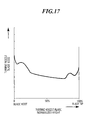
- FIG.17 shows the radial direction distribution of aerodynamic loss in prior art turbine nozzle blades.
- S/T throat ⁇ pitch ratio
- a desirable objective therefore, has been of an overall three-dimensional design method that takes account of the effect by which the flow distribution in the circumferential direction is varied, and the effect of blade deformation due to centrifugal force.
- the prior art solutions to date have not eliminated all problems.
- One such solution now will be described with reference to FIGS. 14 and 15.
- a row of turbine moving blades is designed in a form in which the leading. edge is twisted in the clockwise direction from the blade root to the blade tip. Therefore, when a tensile load due to centrifugal force acts on the blade effective portion 9 , twist-return (untwisting ) occurs in the direction of arrow AR shown in FIG.14.
- the throat- pitch ratio ( S/T ) of the turbine moving blade 4 although set in the distribution shown by the solid line from blade root to blade tip when at rest, theoretically changes to the distribution shown by the broken line during operation.
- the measures taken to control vibration of the turbine moving blades i.e., the intermediate connectors 11 in the intermediate part of the blade effective portion 9 and tip connectors 10 at the blade tips
- the throat- pitch ratio ( S/T ) distribution in the about 70% to about 95 % height that is normalized between connectors 10 and 11 as shown in FIG.15, swells outward and becomes a broad passage.
- Prior art steam turbines thus suffer from many drawbacks. They adopt throat- pitch ratio ( S/T ) distributions that yield almost uniform flow distributions in the radial direction, resulting in high frictional losses close to the wall surface at the blade roots of the turbine moving blades and close to the outer wall surface of the turbine nozzle blade tips. They also can suffer from shock waves caused by the interaction of supersonic steam flow with swollen blade portions between the restricted parts of the blade effective portion 9 due to blade untwisting. These drawbacks prevent the turbine form performing in accordance with design criteria.
- a three-dimensional blade design method devised and adopted for a turbine moving blade of the present invention is one that treats the turbine driving steam as a three-dimensional flow, and can control that three-dimensional flow. Therefore, accuracy is greater than with the prior art simplified three-dimensional blade design method.
- the throat ⁇ pitch ratio ( S/T ) of the turbine moving blades is off-set prior to operation.
- S/T throat ⁇ pitch ratio
- FIG. 1 is a schematic partial sectional view showing an embodiment of a steam turbine according to the present invention.
- FIG.2 is a loss distribution graph for a turbine moving blade assembly according to the present invention.
- FIG.3 is a superimposed plan view showing individual blade sectional views cut at arbitrary positions along the height of a turbine moving blade from blade root to blade tip according to the present invention.
- FIG.4 is a static throat pitch ratio ( S/T ) distribution graph for a turbine moving blade according to the present invention compared with a prior art static throat ⁇ pitch ratio ( S/T ) distribution and a throat pitch ratio ( S/T ) distribution when operating.
- FIG.5 is a throat ⁇ pitch ratio ( S/T ) distribution graph showing a static throat pitch ratio ( S/T ) from a blade height of about 0% to a blade height of about 50% for a turbine moving according to the present invention.
- FIG.6 is a throat pitch ratio (SIT) distribution graph comparing throat pitch ratio ( S/T ) from a blade height of about 0% to a blade height of about 100% for a turbine moving according to the present invention when at rest and when operating.
- SIT throat pitch ratio
- FIG.7 is a throat pitch ratio ( S/T ) distribution graph showing throat ⁇ pitch ratio ( S/T ) from a blade height of about 0% to a blade height of about 100% for a turbine nozzle blade according to the present invention.
- FIG. 8 is a turbine stage loss distribution graph showing the relationship between throat pitch ratio ( S/T ) at the blade root and turbine stage loss for a turbine nozzle blade according to the present invention.
- FIG.9 is a turbine stage loss distribution graph showing the relationship between throat ⁇ pitch ratio ( S/T ) at the blade tip and turbine stage loss for a turbine nozzle blade according to the present invention.
- FIG.10 is a schematic sectional view showing a turbine nozzle blade and a turbine moving blade in a final turbine stage.
- FIG. 11 is a partial sectional view taken along line 11-11 in Fig. 10, showing an intermediate connector.
- FIG.12 is a schematic oblique view of blade tip connectors viewed from the direction of arrows 12 - 12 in FIG. 10.
- FIG.13 is a schematic drawing showing equivalent velocity graphs for inflowing turbine driving steam for each of blade root, blade mean diameter and a blade tip positions of a turbine moving blade in a final stage.
- FIG.14 is a partial development sectional view showing a blade row of turbine moving blades in a final turbine stage.
- FIG.15 is a throat- pitch ratio ( S/T ) distribution graph comparing throat pitch ratio ( S/T ) when at rest and throat ⁇ pitch ratio ( S/T ) during operation for a turbine moving blade in the final turbine stage.
- FIG.16 is a throat pitch ratio ( S/T ) distribution graph showing throat pitch ratio ( S/T ) for a turbine nozzle blade in a final turbine stage.
- FIG.17 is a loss distribution graph for a turbine nozzle blade in a final turbine stage.
- a turbine stage 22 is composed of an assembly of turbine nozzle blades 20 , which are supported at their ends by an inner diaphragm 23 and an outer diaphragm 24 , and an assembly of turbine moving blades 21 , which are embedded in the turbine shaft 25 .
- a plurality of such turbine stages 22 are arranged along the turbine shaft 25 .
- the blades are made of an alloy of about 88% to about 92% titanium, about 4% to about 8% aluminium and about 2% to about 6% vanadium by weight percent.
- a rotation speed of 3000rpm is used in 50Hz areas and a rotation speed of 3600rpm is used in 60Hz areas.
- Each turbine moving blade 21 has a blade embedded part 26 and a blade effective portion 27 . Also, each turbine moving blade 21 is provided with a blade tip connector 28 at the blade tip, and an intermediate connector 29 at the blade intermediate part.
- the diameter of the blade root of the blade effective portion 27 is 1.4m or more, and the blade height is 1.0m or more.
- the intermediate connector 29 is installed in a position in the about 50% to about 70% range of normalized blade height and is designed to reduce vibration of the turbine moving blades 21 during operation and, simultaneously, to suppress any untwisting of the turbine moving blade 21 to a low level.
- the blade tip connector 28 and the intermediate connector 29 are respectively of the same configurations as shown in FIG. 11 and FIG.12, and described above in reference to those figures.
- the turbine moving blade 21 has a blade row performance distribution shown in FIG.2.
- This blade row performance distribution shows aerodynamic loss (turbine moving blade loss) on the vertical axis and normalized blade height on the horizontal axis, respectively, and shows that aerodynamic loss becomes small in the normalized blade height range of about 15 to about 45%.
- This blade row performance distribution was obtained by numeric analysis of the turbine driving steam flow, and agrees well with experimental data for model turbines and, as such, is effective data when carrying out three-dimensional design of a blade row.
- the three-dimensional flow pattern of the turbine blade row can be optimized by the appropriate setting of throat ⁇ pitch ratio ( S/T ), where the pitch between one blade effective portion 27a and the adjacent blade effective portion 27b is taken as T , and the width of the flow throat (the narrowest passage) formed by the back 30 of the one blade effective portion 27a and the belly of the adjacent blade effective portion 27b is taken as S.
- S/T throat ⁇ pitch ratio
- the twist angle is given in the clockwise direction so that cross-section A 0 shifts from point P 0 to point Q 0 , cross-section A 15 shifts from point P 15 to point Q 15 and cross-section A 85 shifts from point P 85 to point Q 85 , and also the twist angle is given in the anti-clockwise direction so that cross-section A 30 shifts from point P 30 to point Q 30 and cross-section A 100 shifts from point P 100 to point Q 100 .
- Offset leading edge ridge line OLERL is formed by the solid line that joins a leading edges 32, 32, ... of each cross-section A 0 , A 15 , ....
- the twist angles given to each cross-section A 0 , A 30 ... are in the clockwise or anti-clockwise direction when viewed with the leading edges on the left and, at the same time, with the backs facing upwardly.
- throat ⁇ pitch ratio S/T
- S/T throat ⁇ pitch ratio
- throat ⁇ pitch ratio ( S/T ) for each cross-section A 0 , A 15 , ... is determined based on the blade twist angle, that throat- pitch ratio ( S/T ) distribution, as shown by the solid line in FIG.4, forms a roughly S-shaped curve having a maximal value and a minimal value.
- the solid line is markedly shifted from the prior art throat- pitch ratio ( S/T ) position shown by the single-dot chain line, and is maintained, so-to-speak, off-set.
- maximum value and "minimal value” are defined as follows:.
- throat ⁇ pitch ratio ( S/T ) is determined beforehand by giving a greater twist angle than in the prior art to each cross-section A 0 , A 15 , ..., and the determined ( S/T ) is off-set to the position shown by the solid line.
- This differential twist angle (as compare to the prior art) is defined herein as the "differential blade twist angle"
- the throat pitch ratio ( S/T ) distribution graph for the turbine moving blade 21 shown in FIG.4 is one in which the differential blade twist angle was set over all blade cross-sections A 0 , A 15 , ... for the entire blade from blade root to blade tip.
- whether to impart the differential blade twist angle over the entire length of the blade, or over a smaller portion of the blade depends on whether the turbine driving steam flow is subsonic, transonic, or supersonic.
- throat ⁇ pitch ratio ( S/T ) is determined by giving a differential blade twist angle to each blade cross-section in the blade height range from about 10% to about 45%, taking the blade root (blade height 0%) as the reference, and the predetermined throat ⁇ pitch ratio ( S/T ) distribution is formed as a curve having at least one minimal value or maximal value, or forms a so-called S-shaped curve having a minimal value and a maximal value.
- the minimal value of throat- pitch ratio ( S/T ) should be formed in at a blade height position in the range from about 10% to about 20%, and the maximal value of throat ⁇ pitch ratio ( S/T ) should be formed at a blade height position in the range from about 15% to about 45%.
- Predetermining throat- pitch ratio ( S/T ) by giving a differential blade twist angle to each cross-section in the blade height range from about 10% to about 45%, and setting the throat- pitch ratio ( S/T ) distribution curve to have at least one minimal value or maximal value or an S-shaped curve having a minimal value and a maximal value as described above compensates for blade untwisting that occurs during operation and, at the same time, passes more turbine driving steam in the region where turbine moving blade loss is small, as shown in FIG.2, thus improving turbine row performance.
- special attention must be given to giving a differential blade twist angle at blade height positions of about 10% or less.
- throat ⁇ pitch ratio ( S/T ) is made smaller close to the wall surface (the turbine shaft) at the blade root, the outlet flow angle will become smaller and secondary flow loss will increase due to turbulence in the vicinity of the blade root in the corner between the blade and the embedded portion, where a root fillet is added in order to relieve stress concentration.
- the actual throat ⁇ pitch ratio ( S/T ) that includes the root fillet it is necessary to adjust the blade twist angle of the root fillet to make the throat- pitch ratio ( S/T ) larger.
- the throat ⁇ pitch ratios ( S/T ) are predetermined by giving a differential blade twist angle to each blade cross-section from a blade height of about 10% to a blade height of about 95%.
- the distribution of the predetermined throat ⁇ pitch ratios ( S/T ) thus forms an S-shaped curve which has a minimal value and a maximal value in the blade height range from about 10% to about 95 % and, at the same time, is off-set in a curve having a minimal value in a blade height range from about 70% to about 95%, and preferably in the range from about 80% to about 90%.
- This arrangement suppresses the swollen portion (shown in FIG.15) which occurs when the blades untwist during operation, and ensures that turbine driving steam flow remains in a stable state, thus suppressing the generation of shock waves.
- throat ⁇ pitch ratio results from giving differential blade twist angles to the cross-sections as if a maximal value were formed in the blade height range of about 20% to about 80%; setting throat- pitch ratio ( S/T ) at the blade root (blade height 0%) in the range about 0.1 to about 0.5; and setting throat ⁇ pitch ratio ( S/T ) at the blade tip (blade height 100%) in the range about 0.14 to about 0.5, respectively.
- the total loss turbine nozzle blade loss plus turbine moving blade loss
- throat- pitch ratio ( S/T ) shown in FIG.8 is the preferred application range obtained from a model turbine. If the throat ⁇ pitch ratios ( S/T ) at the blade root and the blade tip become too small, the rapid increase in loss occurs with the above-mentioned value as a boundary because the secondary (turbulent) flow loss close to the wall surface rapidly increases with this value as a boundary. Also, the flow distribution balance across the radial direction is upset causing an excessively large flow at the wall surface and rapidly increasing frictional loss close to the wall.
- throaty pitch ratio ( S/T ) at the tip (blade height 100%) to about 0.14 to about 0.5 is based on the fact that, as shown in FIG.9, the turbine stage loss will become smaller.
- This range of throat ⁇ pitch ratio ( S/T ) at the tip is the preferred application range, and similarly is obtained from a model turbine.
- the throaty pitch ratio ( S/T ) for turbine nozzle blades 20 is determined by giving a differential blade twist angle to the blade cross-sections such that the distribution of the throat- pitch ratio ( S/T ) is caused to swell outward, as if the maximal value were formed, within a blade height range of about 20% to about 80%.
- the throat- pitch ratio ( S/T ) at the blade root (blade height 0%) is set in the range of about 0.1 to about 0.5
- the throat ⁇ pitch ratio ( S/T ) at the blade tip (blade height 100%) is set in the range of about 0.14 to about 0.5.
- throat ⁇ pitch ratio ( S/T ) may also be adjusted by varying the curvature from the part that forms the suction surface throat to the trailing edge. That is, if the curvature of the part forming the back throat to the trailing edge is made smaller, the trailing edge will come closer to the back of the adjacent blade and the throat ⁇ pitch ratio ( S/T ) will become smaller. Conversely, if the curvature is made larger, the throat ⁇ pitch ratio ( S/T ) will become larger. Further, the throat ⁇ pitch ratio ( S/T ) can be adjusted by varying the trailing edge thickness. However, since the blade row performance will be reduced if the trailing edge is made thicker, it will be necessary to make other adjustments such that overall efficiency will be maintained.
- the distribution of the throat ⁇ pitch ratio ( S/T ) determined according to the differential blade twist angle, which is given to the blade cross-sections, is off-set so that it becomes larger than in the prior art and, during operation, the throaty pitch ratio ( S/T ) thus is maintained at an optimum value. Therefore, the turbine driving steam flows in a more stable state, and turbine blade row performance is improved.
- the distribution of the throat ⁇ pitch ratio ( S/T ) determined according to the differential blade twist angle, which is given to the blade cross-sections, is made to swell in the outward direction as if the maximal value were formed.
- S/T the differential blade twist angle
Landscapes
- Engineering & Computer Science (AREA)
- Mechanical Engineering (AREA)
- General Engineering & Computer Science (AREA)
- Physics & Mathematics (AREA)
- Fluid Mechanics (AREA)
- Turbine Rotor Nozzle Sealing (AREA)
- Control Of Turbines (AREA)
Abstract
Description
At the same time, the solid line is markedly shifted from the prior art throat- pitch ratio (S/T) position shown by the single-dot chain line, and is maintained, so-to-speak, off-set. Here, "maximal value" and "minimal value" are defined as follows:.
Claims (16)
- In a turbine moving blade assembly for a steam turbine which has a plurality of stages (22) each provided with turbine moving blades (21) attached to the turbine shaft (25) and fixed turbine nozzle blades (20) positioned axially adjacent the turbine moving blades, the turbine moving blades (21) being circumferentially spaced with adjacent turbine moving blades being interconnected intermediate their ends and also at their radially outer tips, each of the turbine moving blades (21) being twisted from blade root to blade tip, wherein the twist angles at blade cross-sections along the height of each turbine moving blade (21) are differentially twisted to produce a distribution of throat- pitch ratio (S/T) along the turbine moving blade height direction from blade root to blade tip that follows a curve having at least one minimal value and one maximal value.
- A turbine moving blade assembly according to claim 1, wherein said throat-pitch ratio (S/T) distribution is off-set to take into account turbine moving blade untwisting that occurs during operation of the steam turbine due to centrifugal force.
- A turbine moving blade assembly according to claim 1 or claim 2, wherein the maximal value is located in the turbine moving blade height range of about 15 % to about 45 %.
- A turbine moving blade assembly according to claim 3, wherein said minimal value is located in the turbine moving blade height range of about 10% to about 20%, and the maximal value is located in the turbine moving blade height range of about 25 % to about 35 %.
- A turbine moving blade assembly according to claim 1 or claim 2, wherein the minimal value is located in the turbine moving blade height range of about 70% to about 95 %.
- A turbine moving blade assembly according to claim 3, wherein the minimal value is located in the turbine moving blade height range of about 70% to about 95 %.
- A turbine moving blade assembly according to claim 1 or claim 2, wherein some of the differential blade twist angles are given to blade cross-sections in a clock-wise direction, and some of the differential twist angles are given to blade cross-sections in an anti-clockwise direction.
- A turbine moving blade assembly according to claim 7, wherein the differential blade twist angles given in a clockwise direction are in positions in a turbine moving blade height range from about 0% to about 15 %, and in positions in a turbine moving blade height range of about 85 %, while the differential blade twist angles given in an anti-clockwise direction are at about 30% blade height position and at about 100% blade height position.
- A turbine moving blade assembly according to claim 1 or claim 2, wherein the turbine moving blade assembly has a diameter of at least 1.4m at the root, the turbine moving blade height is at least 1.0m, and the turbine shaft rotates at 3000rpm or 3600rpm.
- A turbine moving blade assembly according to claim 1 or claim 2, wherein said turbine moving blades are made of a titanium alloy with a composition of about 88 % to about 92 % titanium, about 4 % to about 8 % aluminium and about 2 % to about 6 % vanadium by weight percent.
- A turbine moving blade assembly according to claim 1 or claim 2, wherein the intermediate connections of the turbine moving blades are located within a turbine moving blade height range of about 50% to about 70%.
- A turbine moving blade assembly according to claim 1, wherein the turbine moving blade differential twist angles are adopted in a final turbine stage and at least one turbine stage upstream of the final turbine.
- In a turbine nozzle blade assembly for a steam turbine which has a plurality of stages (22) each provided with turbine moving blades (21) attached to the turbine shaft (25) and fixed turbine nozzle blades (20) positioned axially adjacent the turbine moving blades (21), each of the turbine nozzle blades (20) being twisted from blade root to blade tip, wherein the twist angles at blade cross-sections along the height of each turbine nozzle blade are differentially twisted to produce a distribution of throat· pitch ratio (S/T) along the turbine moving blade height direction from blade root to blade tip that follows a curve having at least one maximal value located in a turbine nozzle blade height range of about 20 % to about 80 %.
- A turbine nozzle blade assembly according to claim 13, wherein said distribution of throat pitch ratio (S/T) is located in a range of about 0. 1 to about 0.5 at the blade root position and in a range of about 0. 14 to about 0.5 at the blade tip position.
- A turbine nozzle blade assembly according to claim 13, wherein the turbine nozzle blade differential twist angles are adopted in a final turbine stage and at least one turbine stage upstream of the final turbine.
- In a steam turbine having a casing, a shaft rotatable in a the casing and a plurality of stages (22) each provided with turbine moving blades (21) attached to the turbine shaft (25) and fixed turbine nozzle blades (20) positioned axially adjacent the turbine moving blades, the turbine moving blades (21) being circumferentially spaced with adjacent turbine moving blades interconnected intermediate their ends and also at their radially outer tips, each of the turbine moving blades (21) being twisted from blade root to blade tip, wherein the twist angles at blade cross-sections along the height of each turbine moving blade are differentially twisted to produce a distribution of throat· pitch ratio (S/T) along the turbine moving blade height direction from blade root to blade tip that follows a curve having at least one minimal value and one maximal value.
Applications Claiming Priority (2)
| Application Number | Priority Date | Filing Date | Title |
|---|---|---|---|
| JP10218262A JP2000045704A (en) | 1998-07-31 | 1998-07-31 | Steam turbine |
| JP21826298 | 1998-07-31 |
Publications (3)
| Publication Number | Publication Date |
|---|---|
| EP0985801A2 true EP0985801A2 (en) | 2000-03-15 |
| EP0985801A3 EP0985801A3 (en) | 2000-12-13 |
| EP0985801B1 EP0985801B1 (en) | 2004-09-22 |
Family
ID=16717124
Family Applications (1)
| Application Number | Title | Priority Date | Filing Date |
|---|---|---|---|
| EP99114881A Expired - Lifetime EP0985801B1 (en) | 1998-07-31 | 1999-07-29 | Blade configuration for steam turbine |
Country Status (6)
| Country | Link |
|---|---|
| US (3) | US6375420B1 (en) |
| EP (1) | EP0985801B1 (en) |
| JP (1) | JP2000045704A (en) |
| KR (1) | KR100362833B1 (en) |
| CN (1) | CN1239810C (en) |
| DE (1) | DE69920358T2 (en) |
Cited By (7)
| Publication number | Priority date | Publication date | Assignee | Title |
|---|---|---|---|---|
| WO2003018961A1 (en) * | 2001-08-31 | 2003-03-06 | Kabushiki Kaisha Toshiba | Axial flow turbine |
| EP1462610A1 (en) * | 2003-03-28 | 2004-09-29 | Siemens Aktiengesellschaft | Rotor blade row for turbomachines |
| EP1612372A1 (en) * | 2004-07-01 | 2006-01-04 | Alstom Technology Ltd | Turbine blade with a cut-back at the tip or the root of the blade |
| EP2177714A2 (en) * | 2008-10-14 | 2010-04-21 | General Electric Company | Blade for a low pressure section of a steam turbine engine |
| EP2479381A1 (en) * | 2011-01-21 | 2012-07-25 | Alstom Technology Ltd | Axial flow turbine |
| WO2014007994A1 (en) | 2012-07-02 | 2014-01-09 | United Technologies Corporation | Airfoil for improved flow distribution with high radial offset |
| CN106894847A (en) * | 2015-12-18 | 2017-06-27 | 通用电气公司 | Turbine and its turbine nozzle |
Families Citing this family (35)
| Publication number | Priority date | Publication date | Assignee | Title |
|---|---|---|---|---|
| JP2000045704A (en) * | 1998-07-31 | 2000-02-15 | Toshiba Corp | Steam turbine |
| US6682301B2 (en) * | 2001-10-05 | 2004-01-27 | General Electric Company | Reduced shock transonic airfoil |
| US7312149B2 (en) * | 2004-05-06 | 2007-12-25 | Taiwan Semiconductor Manufacturing Co., Ltd. | Copper plating of semiconductor devices using single intermediate low power immersion step |
| CN100339559C (en) * | 2005-07-31 | 2007-09-26 | 东方电气集团东方汽轮机有限公司 | Last stage rotor blade of steam turbine |
| US20090214345A1 (en) * | 2008-02-26 | 2009-08-27 | General Electric Company | Low pressure section steam turbine bucket |
| DE102008031781B4 (en) * | 2008-07-04 | 2020-06-10 | Man Energy Solutions Se | Blade grille for a turbomachine and turbomachine with such a blade grille |
| US8313292B2 (en) * | 2009-09-22 | 2012-11-20 | Siemens Energy, Inc. | System and method for accommodating changing resource conditions for a steam turbine |
| US20110097205A1 (en) * | 2009-10-28 | 2011-04-28 | General Electric Company | Turbine airfoil-sidewall integration |
| ITMI20101447A1 (en) * | 2010-07-30 | 2012-01-30 | Alstom Technology Ltd | "LOW PRESSURE STEAM TURBINE AND METHOD FOR THE FUNCTIONING OF THE SAME" |
| US8790082B2 (en) | 2010-08-02 | 2014-07-29 | Siemens Energy, Inc. | Gas turbine blade with intra-span snubber |
| US20140041602A1 (en) * | 2011-03-07 | 2014-02-13 | Multiwing International A/S | Engine cooling fan |
| JP5868605B2 (en) | 2011-03-30 | 2016-02-24 | 三菱重工業株式会社 | gas turbine |
| US8777564B2 (en) | 2011-05-17 | 2014-07-15 | General Electric Company | Hybrid flow blade design |
| US9051843B2 (en) | 2011-10-28 | 2015-06-09 | General Electric Company | Turbomachine blade including a squeeler pocket |
| US9255480B2 (en) * | 2011-10-28 | 2016-02-09 | General Electric Company | Turbine of a turbomachine |
| US8967959B2 (en) * | 2011-10-28 | 2015-03-03 | General Electric Company | Turbine of a turbomachine |
| US8992179B2 (en) | 2011-10-28 | 2015-03-31 | General Electric Company | Turbine of a turbomachine |
| US8998577B2 (en) * | 2011-11-03 | 2015-04-07 | General Electric Company | Turbine last stage flow path |
| EP2653658A1 (en) * | 2012-04-16 | 2013-10-23 | Siemens Aktiengesellschaft | Guide blade assembly for an axial flow machine and method for laying the guide blade assembly |
| CN102926821A (en) * | 2012-11-07 | 2013-02-13 | 哈尔滨汽轮机厂有限责任公司 | 900mm last stage moving blade for combined cycle steam turbine |
| JP5836410B2 (en) * | 2014-02-27 | 2015-12-24 | 三菱重工業株式会社 | Rotor blade and rotating machine |
| JP6081398B2 (en) * | 2014-03-12 | 2017-02-15 | 株式会社東芝 | Turbine blade cascade, turbine stage and steam turbine |
| EP3023585B1 (en) * | 2014-11-21 | 2017-05-31 | General Electric Technology GmbH | Turbine arrangement |
| US10323528B2 (en) * | 2015-07-01 | 2019-06-18 | General Electric Company | Bulged nozzle for control of secondary flow and optimal diffuser performance |
| CN105499918B (en) * | 2015-12-03 | 2017-10-24 | 哈尔滨汽轮机厂有限责任公司 | A kind of supercritical pressure turbine pretwist type guide vane assembly method |
| US9957804B2 (en) * | 2015-12-18 | 2018-05-01 | General Electric Company | Turbomachine and turbine blade transfer |
| US9957805B2 (en) * | 2015-12-18 | 2018-05-01 | General Electric Company | Turbomachine and turbine blade therefor |
| US10247006B2 (en) * | 2016-07-12 | 2019-04-02 | General Electric Company | Turbine blade having radial throat distribution |
| CN106256993A (en) * | 2016-08-09 | 2016-12-28 | 杭州汽轮机股份有限公司 | A kind of final stage moving blade of feed pump industrial steam turbine |
| US10502073B2 (en) * | 2017-03-09 | 2019-12-10 | General Electric Company | Blades and damper sleeves for a rotor assembly |
| DE102018211158A1 (en) * | 2018-07-06 | 2020-01-09 | MTU Aero Engines AG | Blade arrangement for a gas turbine and method for producing the blade arrangement |
| CN109578085B (en) * | 2018-12-26 | 2021-06-22 | 中国船舶重工集团公司第七0三研究所 | Method for weakening unsteady acting force of turbine movable blade through guide blade inclination |
| DE112020002877T5 (en) * | 2019-06-14 | 2022-03-10 | Ihi Corporation | turbocharger |
| US11220910B2 (en) * | 2019-07-26 | 2022-01-11 | Pratt & Whitney Canada Corp. | Compressor stator |
| CN114483311A (en) * | 2021-12-31 | 2022-05-13 | 北京动力机械研究所 | Compact type double-medium air inlet structure |
Citations (1)
| Publication number | Priority date | Publication date | Assignee | Title |
|---|---|---|---|---|
| JPH10218262A (en) | 1997-02-12 | 1998-08-18 | Osaka Ship Building Co Ltd | Aerosol product |
Family Cites Families (19)
| Publication number | Priority date | Publication date | Assignee | Title |
|---|---|---|---|---|
| US2935246A (en) | 1949-06-02 | 1960-05-03 | Onera (Off Nat Aerospatiale) | Shock wave compressors, especially for use in connection with continuous flow engines for aircraft |
| CH557468A (en) * | 1973-04-30 | 1974-12-31 | Bbc Brown Boveri & Cie | TURBINE OF AXIAL DESIGN. |
| JPS614965A (en) | 1984-06-20 | 1986-01-10 | Hitachi Tokyo Electronics Co Ltd | Tachometer voltage generating device |
| US4643645A (en) | 1984-07-30 | 1987-02-17 | General Electric Company | Stage for a steam turbine |
| GB2162587B (en) | 1984-07-30 | 1988-05-05 | Gen Electric | Steam turbines |
| JPH01182504A (en) * | 1988-01-12 | 1989-07-20 | Mitsubishi Heavy Ind Ltd | Reforming method for surface of turbine blade |
| US5035578A (en) * | 1989-10-16 | 1991-07-30 | Westinghouse Electric Corp. | Blading for reaction turbine blade row |
| JPH03267506A (en) * | 1990-03-19 | 1991-11-28 | Hitachi Ltd | Stationary blade of axial flow turbine |
| US5221181A (en) * | 1990-10-24 | 1993-06-22 | Westinghouse Electric Corp. | Stationary turbine blade having diaphragm construction |
| JP2841970B2 (en) * | 1991-10-24 | 1998-12-24 | 株式会社日立製作所 | Gas turbine and nozzle for gas turbine |
| US5286168A (en) | 1992-01-31 | 1994-02-15 | Westinghouse Electric Corp. | Freestanding mixed tuned blade |
| US5203676A (en) | 1992-03-05 | 1993-04-20 | Westinghouse Electric Corp. | Ruggedized tapered twisted integral shroud blade |
| US5267834A (en) | 1992-12-30 | 1993-12-07 | General Electric Company | Bucket for the last stage of a steam turbine |
| JP3132944B2 (en) | 1993-03-17 | 2001-02-05 | 三菱重工業株式会社 | Three-dimensional design turbine blade |
| US5480285A (en) * | 1993-08-23 | 1996-01-02 | Westinghouse Electric Corporation | Steam turbine blade |
| US5326221A (en) * | 1993-08-27 | 1994-07-05 | General Electric Company | Over-cambered stage design for steam turbines |
| US5393200A (en) * | 1994-04-04 | 1995-02-28 | General Electric Co. | Bucket for the last stage of turbine |
| US5695323A (en) * | 1996-04-19 | 1997-12-09 | Westinghouse Electric Corporation | Aerodynamically optimized mid-span snubber for combustion turbine blade |
| JP2000045704A (en) * | 1998-07-31 | 2000-02-15 | Toshiba Corp | Steam turbine |
-
1998
- 1998-07-31 JP JP10218262A patent/JP2000045704A/en active Pending
-
1999
- 1999-07-27 US US09/361,570 patent/US6375420B1/en not_active Expired - Lifetime
- 1999-07-29 EP EP99114881A patent/EP0985801B1/en not_active Expired - Lifetime
- 1999-07-29 DE DE69920358T patent/DE69920358T2/en not_active Expired - Lifetime
- 1999-07-29 KR KR1019990031063A patent/KR100362833B1/en not_active IP Right Cessation
- 1999-07-30 CN CNB991110692A patent/CN1239810C/en not_active Expired - Lifetime
-
2001
- 2001-12-26 US US10/025,597 patent/US6769869B2/en not_active Expired - Lifetime
- 2001-12-26 US US10/025,557 patent/US20020054817A1/en not_active Abandoned
Patent Citations (1)
| Publication number | Priority date | Publication date | Assignee | Title |
|---|---|---|---|---|
| JPH10218262A (en) | 1997-02-12 | 1998-08-18 | Osaka Ship Building Co Ltd | Aerosol product |
Cited By (12)
| Publication number | Priority date | Publication date | Assignee | Title |
|---|---|---|---|---|
| WO2003018961A1 (en) * | 2001-08-31 | 2003-03-06 | Kabushiki Kaisha Toshiba | Axial flow turbine |
| US7048509B2 (en) | 2001-08-31 | 2006-05-23 | Kabushiki Kaisha Toshiba | Axial flow turbine |
| EP1462610A1 (en) * | 2003-03-28 | 2004-09-29 | Siemens Aktiengesellschaft | Rotor blade row for turbomachines |
| EP1612372A1 (en) * | 2004-07-01 | 2006-01-04 | Alstom Technology Ltd | Turbine blade with a cut-back at the tip or the root of the blade |
| EP2177714A2 (en) * | 2008-10-14 | 2010-04-21 | General Electric Company | Blade for a low pressure section of a steam turbine engine |
| EP2177714A3 (en) * | 2008-10-14 | 2014-03-26 | General Electric Company | Blade for a low pressure section of a steam turbine engine |
| EP2479381A1 (en) * | 2011-01-21 | 2012-07-25 | Alstom Technology Ltd | Axial flow turbine |
| JP2012154332A (en) * | 2011-01-21 | 2012-08-16 | Alstom Technology Ltd | Axial flow turbine |
| US8757967B2 (en) | 2011-01-21 | 2014-06-24 | Alstom Technology Ltd | Axial flow turbine |
| WO2014007994A1 (en) | 2012-07-02 | 2014-01-09 | United Technologies Corporation | Airfoil for improved flow distribution with high radial offset |
| EP2867510A4 (en) * | 2012-07-02 | 2015-10-14 | United Technologies Corp | Airfoil for improved flow distribution with high radial offset |
| CN106894847A (en) * | 2015-12-18 | 2017-06-27 | 通用电气公司 | Turbine and its turbine nozzle |
Also Published As
| Publication number | Publication date |
|---|---|
| US20020054817A1 (en) | 2002-05-09 |
| EP0985801B1 (en) | 2004-09-22 |
| CN1239810C (en) | 2006-02-01 |
| US6769869B2 (en) | 2004-08-03 |
| CN1243910A (en) | 2000-02-09 |
| JP2000045704A (en) | 2000-02-15 |
| EP0985801A3 (en) | 2000-12-13 |
| KR100362833B1 (en) | 2002-11-30 |
| DE69920358D1 (en) | 2004-10-28 |
| US20020048514A1 (en) | 2002-04-25 |
| US6375420B1 (en) | 2002-04-23 |
| DE69920358T2 (en) | 2006-02-23 |
| KR20000012075A (en) | 2000-02-25 |
Similar Documents
| Publication | Publication Date | Title |
|---|---|---|
| EP0985801B1 (en) | Blade configuration for steam turbine | |
| EP3124794B1 (en) | Axial flow compressor with end-wall contouring | |
| KR100248129B1 (en) | Blade for axial fluid machine | |
| JP6514644B2 (en) | Structure and method for forcibly coupling the flow fields of adjacent wing elements of a turbomachine, and turbomachine incorporating the same | |
| CN100489276C (en) | Axial flow turbine | |
| US6126394A (en) | Turbine nozzle and moving blade of axial-flow turbine | |
| US7229248B2 (en) | Blade structure in a gas turbine | |
| JP2003201802A (en) | Impeller for radial turbine | |
| US6776582B2 (en) | Turbine blade and turbine | |
| JP3883245B2 (en) | Axial flow turbine | |
| JP2021063456A (en) | Blade of turbomachine, method for designing blade, and method for manufacturing impeller | |
| JP3697296B2 (en) | Turbine blade | |
| WO2000061918A2 (en) | Airfoil leading edge vortex elimination device | |
| JPH05222901A (en) | Structure of stationary blade of turbine | |
| JPH10131707A (en) | Blade group of axial flow turbine | |
| JPH11229805A (en) | Turbine blade and steam turbine | |
| JP4846139B2 (en) | Hydraulic machine | |
| JPH0478803B2 (en) | ||
| JP4402503B2 (en) | Wind machine diffusers and diffusers | |
| JPH11173104A (en) | Turbine rotor blade | |
| JP2001221005A (en) | Three-dimensional axial flow turbine stage | |
| JPH1061405A (en) | Stationary blade of axial flow turbo machine | |
| JPH10220202A (en) | Axial turbine | |
| JP2000248903A (en) | Axial flow turbine | |
| JP4950958B2 (en) | Turbine blades and axial turbines |
Legal Events
| Date | Code | Title | Description |
|---|---|---|---|
| PUAI | Public reference made under article 153(3) epc to a published international application that has entered the european phase |
Free format text: ORIGINAL CODE: 0009012 |
|
| AK | Designated contracting states |
Kind code of ref document: A2 Designated state(s): DE FR GB SE |
|
| AX | Request for extension of the european patent |
Free format text: AL;LT;LV;MK;RO;SI |
|
| PUAL | Search report despatched |
Free format text: ORIGINAL CODE: 0009013 |
|
| AK | Designated contracting states |
Kind code of ref document: A3 Designated state(s): AT BE CH CY DE DK ES FI FR GB GR IE IT LI LU MC NL PT SE |
|
| AX | Request for extension of the european patent |
Free format text: AL;LT;LV;MK;RO;SI |
|
| 17P | Request for examination filed |
Effective date: 20010607 |
|
| AKX | Designation fees paid |
Free format text: DE FR GB SE |
|
| 17Q | First examination report despatched |
Effective date: 20030905 |
|
| GRAP | Despatch of communication of intention to grant a patent |
Free format text: ORIGINAL CODE: EPIDOSNIGR1 |
|
| RIN1 | Information on inventor provided before grant (corrected) |
Inventor name: SAKAMOTO, TARO Inventor name: TANUMA, TADASHI |
|
| GRAS | Grant fee paid |
Free format text: ORIGINAL CODE: EPIDOSNIGR3 |
|
| GRAA | (expected) grant |
Free format text: ORIGINAL CODE: 0009210 |
|
| AK | Designated contracting states |
Kind code of ref document: B1 Designated state(s): DE FR GB SE |
|
| REG | Reference to a national code |
Ref country code: GB Ref legal event code: FG4D |
|
| REF | Corresponds to: |
Ref document number: 69920358 Country of ref document: DE Date of ref document: 20041028 Kind code of ref document: P |
|
| REG | Reference to a national code |
Ref country code: SE Ref legal event code: TRGR |
|
| PLBE | No opposition filed within time limit |
Free format text: ORIGINAL CODE: 0009261 |
|
| STAA | Information on the status of an ep patent application or granted ep patent |
Free format text: STATUS: NO OPPOSITION FILED WITHIN TIME LIMIT |
|
| ET | Fr: translation filed | ||
| 26N | No opposition filed |
Effective date: 20050623 |
|
| REG | Reference to a national code |
Ref country code: GB Ref legal event code: 746 Effective date: 20070317 |
|
| REG | Reference to a national code |
Ref country code: FR Ref legal event code: PLFP Year of fee payment: 18 |
|
| REG | Reference to a national code |
Ref country code: FR Ref legal event code: PLFP Year of fee payment: 19 |
|
| REG | Reference to a national code |
Ref country code: FR Ref legal event code: PLFP Year of fee payment: 20 |
|
| PGFP | Annual fee paid to national office [announced via postgrant information from national office to epo] |
Ref country code: FR Payment date: 20180612 Year of fee payment: 20 |
|
| PGFP | Annual fee paid to national office [announced via postgrant information from national office to epo] |
Ref country code: DE Payment date: 20180717 Year of fee payment: 20 |
|
| PGFP | Annual fee paid to national office [announced via postgrant information from national office to epo] |
Ref country code: SE Payment date: 20180710 Year of fee payment: 20 Ref country code: GB Payment date: 20180725 Year of fee payment: 20 |
|
| REG | Reference to a national code |
Ref country code: DE Ref legal event code: R071 Ref document number: 69920358 Country of ref document: DE |
|
| REG | Reference to a national code |
Ref country code: GB Ref legal event code: PE20 Expiry date: 20190728 |
|
| PG25 | Lapsed in a contracting state [announced via postgrant information from national office to epo] |
Ref country code: GB Free format text: LAPSE BECAUSE OF EXPIRATION OF PROTECTION Effective date: 20190728 |