EP1612372A1 - Turbine blade with a cut-back at the tip or the root of the blade - Google Patents
Turbine blade with a cut-back at the tip or the root of the blade Download PDFInfo
- Publication number
- EP1612372A1 EP1612372A1 EP04103117A EP04103117A EP1612372A1 EP 1612372 A1 EP1612372 A1 EP 1612372A1 EP 04103117 A EP04103117 A EP 04103117A EP 04103117 A EP04103117 A EP 04103117A EP 1612372 A1 EP1612372 A1 EP 1612372A1
- Authority
- EP
- European Patent Office
- Prior art keywords
- blade
- cut
- region
- platform
- regions
- Prior art date
- Legal status (The legal status is an assumption and is not a legal conclusion. Google has not performed a legal analysis and makes no representation as to the accuracy of the status listed.)
- Granted
Links
- 230000003247 decreasing effect Effects 0.000 claims description 3
- 230000000694 effects Effects 0.000 description 3
- 230000005484 gravity Effects 0.000 description 2
- 230000002250 progressing effect Effects 0.000 description 2
- 238000004904 shortening Methods 0.000 description 2
- 230000035515 penetration Effects 0.000 description 1
- 230000000750 progressive effect Effects 0.000 description 1
- 230000009747 swallowing Effects 0.000 description 1
Images

Classifications
-
- F—MECHANICAL ENGINEERING; LIGHTING; HEATING; WEAPONS; BLASTING
- F01—MACHINES OR ENGINES IN GENERAL; ENGINE PLANTS IN GENERAL; STEAM ENGINES
- F01D—NON-POSITIVE DISPLACEMENT MACHINES OR ENGINES, e.g. STEAM TURBINES
- F01D5/00—Blades; Blade-carrying members; Heating, heat-insulating, cooling or antivibration means on the blades or the members
- F01D5/12—Blades
- F01D5/14—Form or construction
- F01D5/141—Shape, i.e. outer, aerodynamic form
- F01D5/142—Shape, i.e. outer, aerodynamic form of the blades of successive rotor or stator blade-rows
- F01D5/143—Contour of the outer or inner working fluid flow path wall, i.e. shroud or hub contour
-
- F—MECHANICAL ENGINEERING; LIGHTING; HEATING; WEAPONS; BLASTING
- F01—MACHINES OR ENGINES IN GENERAL; ENGINE PLANTS IN GENERAL; STEAM ENGINES
- F01D—NON-POSITIVE DISPLACEMENT MACHINES OR ENGINES, e.g. STEAM TURBINES
- F01D5/00—Blades; Blade-carrying members; Heating, heat-insulating, cooling or antivibration means on the blades or the members
- F01D5/12—Blades
- F01D5/14—Form or construction
- F01D5/141—Shape, i.e. outer, aerodynamic form
- F01D5/145—Means for influencing boundary layers or secondary circulations
Definitions
- the invention pertains to a turbine blade and in particular to a three-dimensional shape of the end-regions of the blade.
- Turbine blades having a suction and pressure side and extending from a hub to a tip and from a leading edge to a trailing edge.
- a chord extends essentially from the leading edge to the trailing edge of the blade.
- the blades are integrally machined with blade platforms, typically of a rhombus shape, for mounting on a rotor.
- the flow of a working medium through a turbine may be described having a core flow in the mid-region between the tip and hub of the blade and flow layers near the end-wall regions. Near the end-wall regions, an inlet boundary layer of the flow rolls about the leading edge of the blades giving rise to horse shoe like vortices flowing along both the pressure as well as the suction side of the blade. Traverse pressure gradients between the pressure side of blades in a given blade row and the suction side of blades in an adjacent blade row act together with radial pressure gradients on the horse shoe vortices and cause complex three-dimensional flow patterns, also known as secondary flows. These constitute a significant portion of the overall losses encountered in turbine stages of low aspect ratio (ratio of longitudinal blade length to chord length).
- a decrease of the chord length near the end-walls can be realised by cutting back the blade profile at the trailing edge and effectively shortening the axial extent of the blade in the end-wall regions.
- a decreased chord length triggers a faster expansion of the end-wall flow, creating a radial pressure gradient such that the penetration of the secondary vortex flow into the main flow in the mid-region of the blade is reduced.
- a turbine blade rotating or stationary, extends from a platform to a tip and comprises a pressure side and suction side, a leading edge and a trailing edge.
- a chord extends between the leading and trailing edge essentially parallel to the platform.
- the blade is considered to have end-regions near the platform and near the tip with a mid region extending radially between the two end regions.
- the trailing edge in one or both of the said end-regions is shaped having a cut-back relative to the mid-region of the trailing edge.
- the blade comprises a twist of the blade in the end-region or end-regions with the cutback in combination with a lean of the end-regions with the cut-back. The lean is directed perpendicular to the chord and such that the pressure side points toward the platform of the blade.
- a cut-back of a blade trailing edge alone would cause an increased throat and flow angle of the blading, which in turn would cause a reduction of the expansion or pressure drop near the endwall.
- a cut-back alone furthermore effects an increase in the loading of the end-regions, as already mentioned. Also, a smaller chord length results in an increased pitch to chord ratio, which leads to a load increase.
- the blade In order to correct for the increase of throat and exit angle, the blade is twisted in the region of the cut-back. This effectively produces a closing of the throat. Throat and flow angle are again restored to their original values without cut-back and the original amount of expansion is restored as well.
- twisting of the blade results in that the profile section at the platform extends locally outside of the rhombus-shaped blade platform resulting in an overhang of the blade over the edge of the platform.
- the lean according to the invention corrects for both the increased loading and the profile section overhang outside the platform.
- the lean of the blade perpendicular to the chord direction effectively produces a higher pressure zone near the end walls, which leads to a reduction of the load in the end-regions to levels comparable to a blade without cut-back.
- the lean is realised by a translation of the end-region, which brings back the overhang portion of the blade to within the extent of the blade platform. It is predominantly in the cut-back end-region.
- the amount of lean is determined by the initial amount of cut-back and amount of twist necessary for the closing of the throat.
- the extent of the cut-back is determined according to the aspect ratio of blade length to chord length. As such, its extent varies according to the type and size of blades in the turbine.
- the blade design according to the invention is equally applicable to both rotating as well as stationary blades.
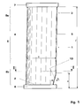
- Figure 1 shows in a side view a rotating turbine blade 1. It extends from a leading edge 4 to a trailing edge 5 and from a hub 2 to a tip 3 essentially in the radial direction with respect to the turbine rotor.
- the blade is mounted on the rotor by means of a blade platform 6, which is an integral part of the blade. It comprises a blade shroud 7 at its tip 3 and end-regions 8a and 8b near the platform and tip respectively, as well as a mid-region 9 between the end-regions.
- the radial extent of the regions 8a, 8b, and 9 vary according to the size of the blade and stage position within the turbine.
- the blade according to the invention has the primary feature of a cut-back 10 of the trailing edge 5 in its end-region.
- the shown embodiment has a cut-back only in the end-region 8b near the hub 2 and platform 6.
- the blade with a cut-back has a reduced chord-length in the end-region near the hub compared to a blade without cut-back.
- the cut-back b extends over a length a in the longitudinal direction of the blade.
- the longitudinal extent a of the cut-back is chosen according to the aspect ratio of blade length l to chord length s, which can vary for example within a range from 0.5 to 6. In general, the smaller the aspect ratio of a blade, the greater is the effect of secondary vortex-flows.
- the extent a of the cut-back is in the range between 0 and 40% of the length l of the blade, where the smaller the aspect ratio, the greater the extent a of the cut-back.
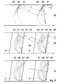
- Figure 2a), b) and c) illustrate the steps of the blade design according to the invention. For purposes of illustration, all design steps are shown in exaggerated manner.
- Figure 2a) shows cross-sectional profiles of two adjacent blades in a blade row. T indicates the tangential direction of the turbine rotor. The figure shows for each blade three profiles at the cross-section along II-II in figure 1 and at two further levels parallel to II-II and within the end-region 8b between the line II-II and the platform 6.
- Profile 21 represents a profile in the mid-region 9 of the blade having no cut-back, while the profiles 22 and 23 represent blade profiles at different levels within the end-region with progressing cut-back and with a progressively shorter chord-length s.
- the profile 23 is at the radial level closest to the blade platform and has the largest b of cut-back. As a result of the cut-back, the throat t' between profiles 23 of the adjacent blades is increased compared to the throat t between profiles 21. The exit angle of the blades is increased as well.
- Figure 2b shows a twisting of the cross-sectional profiles of the end-region 8b relative to one another by means of a rotation of the cross-sectional blade profiles of figure 2a.
- the cross-sectional profiles are rotated in such a way that the trailing edge of the blade is turned in a direction toward the suction side 30 of an adjacent blade in the blade row and as a result the throat is closed or decreased.
- the blade profiles 24, 25, 26 are rotated about a point at or near the leading edge 4, while the cross-sectional blade profiles of the mid-region are left unchanged.
- the cross-sectional profiles could also be rotated about any other point, for example about their center of gravity.
- the twist is realized by rotation of blade profiles about a point on the leading edge or other point such as centre of gravity.
- Profiles 21 and 23 are again shown as reference.
- Profiles 24, 25, 26 show the progressive twist of the blade, profile 26 being the profile closest to the platform 6 and rotated the most. The twist effects a "closing” or decrease of the throat from throat t' between cross-sectional profiles 23 to throat t" between cross-sectional profiles 26.
- the arrow “C” indicates the direction of the "closing" the throat.
- the twist of the blade end-region results in an overhang of the blade profiles close to the blade platform over the edge of the platform 6.
- the blade end-region is leaned toward the platform according to the invention as shown in figure 2c. It illustrates the lean of the end-region by means of a translation of the cross-sectional profiles 27 and 28 with respect to profile 26 along the direction L perpendicular to the chord s. Profile 28 closest to the platform is translated the most with respect to the mid-region and lies within the extent of the blade platform. The amount of necessary translation is determined by the geometry of the platform and aerodynamic considerations.
- the lean is preferably along the direction perpendicular to the chord. However, it can also be along other directions, for example the tangential direction, as long as the resultant blade profile is within the blade platform.
- the complete blade design comprises cross-sectional profiles stacked in the longitudinal direction. Beginning at the cross-sectional level where the cut-back begins (cross-section 21) and moving in the radial direction toward the blade platform, the cross-sectional profiles have a progressing combination of cut-back, twist and lean, ending with cross-section 28.
- Figure 3 shows a perspective view of the blade 1 with a trailing edge cutback in the end-region 8b near the platform 6, a twist of the end-region with respect to the mid-region 9 of the blade, and the lean 31 of the pressure side 32 toward the platform 6 along the line perpendicular to the chord. The lean 31 is most evident along the leading edge 4 in the end-region near the platform 6.
- blade according to the invention have a cut-back in the end-region near the tip, or at both end-regions.
Landscapes
- Engineering & Computer Science (AREA)
- Physics & Mathematics (AREA)
- Fluid Mechanics (AREA)
- Mechanical Engineering (AREA)
- General Engineering & Computer Science (AREA)
- Turbine Rotor Nozzle Sealing (AREA)
Abstract
Description
- The invention pertains to a turbine blade and in particular to a three-dimensional shape of the end-regions of the blade.
- Turbine blades are described having a suction and pressure side and extending from a hub to a tip and from a leading edge to a trailing edge. A chord extends essentially from the leading edge to the trailing edge of the blade. The blades are integrally machined with blade platforms, typically of a rhombus shape, for mounting on a rotor.
- The flow of a working medium through a turbine may be described having a core flow in the mid-region between the tip and hub of the blade and flow layers near the end-wall regions. Near the end-wall regions, an inlet boundary layer of the flow rolls about the leading edge of the blades giving rise to horse shoe like vortices flowing along both the pressure as well as the suction side of the blade. Traverse pressure gradients between the pressure side of blades in a given blade row and the suction side of blades in an adjacent blade row act together with radial pressure gradients on the horse shoe vortices and cause complex three-dimensional flow patterns, also known as secondary flows. These constitute a significant portion of the overall losses encountered in turbine stages of low aspect ratio (ratio of longitudinal blade length to chord length).
- A decrease of the chord length near the end-walls can be realised by cutting back the blade profile at the trailing edge and effectively shortening the axial extent of the blade in the end-wall regions. A decreased chord length triggers a faster expansion of the end-wall flow, creating a radial pressure gradient such that the penetration of the secondary vortex flow into the main flow in the mid-region of the blade is reduced.
- Therefore a shortening of the chord length near the end-walls is advantageous from the point of view of secondary vortex flows. However, there are disadvantages in that a cut-back of the end-regions also leads to a higher load per unit length of the blade, which causes greater secondary flows due to transverse pressure gradients from the pressure side of a blade to the suction side of an adjacent blade.
- Furthermore, a cut-back of the trailing edge results in an increase of the exit angle, which can cause undesirable changes in the swallowing capacity and other key design parameters.
- It is the object of the invention to provide a turbine blade that avoids the above mentioned disadvantages in connection with shortened chord lengths in the end-regions.
A blade according to the invention is disclosed inclaim 1. Particular embodiments of the blade are disclosed in the subclaims. - A turbine blade, rotating or stationary, extends from a platform to a tip and comprises a pressure side and suction side, a leading edge and a trailing edge. A chord extends between the leading and trailing edge essentially parallel to the platform. The blade is considered to have end-regions near the platform and near the tip with a mid region extending radially between the two end regions. According to the invention, the trailing edge in one or both of the said end-regions is shaped having a cut-back relative to the mid-region of the trailing edge. In addition, the blade comprises a twist of the blade in the end-region or end-regions with the cutback in combination with a lean of the end-regions with the cut-back. The lean is directed perpendicular to the chord and such that the pressure side points toward the platform of the blade.
- A cut-back of a blade trailing edge alone would cause an increased throat and flow angle of the blading, which in turn would cause a reduction of the expansion or pressure drop near the endwall. A cut-back alone furthermore effects an increase in the loading of the end-regions, as already mentioned. Also, a smaller chord length results in an increased pitch to chord ratio, which leads to a load increase.
- In order to correct for the increase of throat and exit angle, the blade is twisted in the region of the cut-back. This effectively produces a closing of the throat. Throat and flow angle are again restored to their original values without cut-back and the original amount of expansion is restored as well.
However, such twisting of the blade results in that the profile section at the platform extends locally outside of the rhombus-shaped blade platform resulting in an overhang of the blade over the edge of the platform.
The lean according to the invention corrects for both the increased loading and the profile section overhang outside the platform. - The lean of the blade perpendicular to the chord direction effectively produces a higher pressure zone near the end walls, which leads to a reduction of the load in the end-regions to levels comparable to a blade without cut-back.
- The lean is realised by a translation of the end-region, which brings back the overhang portion of the blade to within the extent of the blade platform. It is predominantly in the cut-back end-region. The amount of lean is determined by the initial amount of cut-back and amount of twist necessary for the closing of the throat.
The extent of the cut-back is determined according to the aspect ratio of blade length to chord length. As such, its extent varies according to the type and size of blades in the turbine. - The blade design according to the invention is equally applicable to both rotating as well as stationary blades.
-
- Figure 1 shows a side view of the blade of figure 1 with the cut-back of the trailing edge,
- figures 2a, b, and c illustrate in several cross-sectional views at different radial levels according to II-II the end-region of the blade. Figure 2a) shows the cut-back, figure 2b) the twist of cross-sectional profiles in the cut-back region, and figure 2c) the lean by means of a relative translation of cross-sectional profiles in the end-region,
- figure 3 shows a perspective view of the blade according to the invention.
- Figure 1 shows in a side view a rotating
turbine blade 1. It extends from a leadingedge 4 to atrailing edge 5 and from ahub 2 to atip 3 essentially in the radial direction with respect to the turbine rotor. The blade is mounted on the rotor by means of ablade platform 6, which is an integral part of the blade. It comprises ablade shroud 7 at itstip 3 and end-regions regions - The blade according to the invention has the primary feature of a cut-
back 10 of thetrailing edge 5 in its end-region. The shown embodiment has a cut-back only in the end-region 8b near thehub 2 andplatform 6. - The blade with a cut-back, as shown, has a reduced chord-length in the end-region near the hub compared to a blade without cut-back. As a result of this measure, secondary vortex-flows are reduced in this end-region. The cut-back b extends over a length a in the longitudinal direction of the blade. The longitudinal extent a of the cut-back is chosen according to the aspect ratio of blade length ℓ to chord length s, which can vary for example within a range from 0.5 to 6. In general, the smaller the aspect ratio of a blade, the greater is the effect of secondary vortex-flows. The extent a of the cut-back is in the range between 0 and 40% of the length ℓ of the blade, where the smaller the aspect ratio, the greater the extent a of the cut-back.
- Figure 2a), b) and c) illustrate the steps of the blade design according to the invention. For purposes of illustration, all design steps are shown in exaggerated manner. Figure 2a) shows cross-sectional profiles of two adjacent blades in a blade row. T indicates the tangential direction of the turbine rotor. The figure shows for each blade three profiles at the cross-section along II-II in figure 1 and at two further levels parallel to II-II and within the end-
region 8b between the line II-II and theplatform 6.Profile 21 represents a profile in themid-region 9 of the blade having no cut-back, while theprofiles - The
profile 23 is at the radial level closest to the blade platform and has the largest b of cut-back. As a result of the cut-back, the throat t' betweenprofiles 23 of the adjacent blades is increased compared to the throat t between profiles 21. The exit angle of the blades is increased as well. - Figure 2b shows a twisting of the cross-sectional profiles of the end-
region 8b relative to one another by means of a rotation of the cross-sectional blade profiles of figure 2a. The cross-sectional profiles are rotated in such a way that the trailing edge of the blade is turned in a direction toward thesuction side 30 of an adjacent blade in the blade row and as a result the throat is closed or decreased. For example, the blade profiles 24, 25, 26 are rotated about a point at or near theleading edge 4, while the cross-sectional blade profiles of the mid-region are left unchanged. The cross-sectional profiles could also be rotated about any other point, for example about their center of gravity. In the case of cut-back in the end-region near the blade tip, the twist is realized by rotation of blade profiles about a point on the leading edge or other point such as centre of gravity. -
Profiles Profiles profile 26 being the profile closest to theplatform 6 and rotated the most. The twist effects a "closing" or decrease of the throat from throat t' betweencross-sectional profiles 23 to throat t" betweencross-sectional profiles 26. The arrow "C" indicates the direction of the "closing" the throat. - However, the twist of the blade end-region results in an overhang of the blade profiles close to the blade platform over the edge of the
platform 6. In order to correct for this overhang, the blade end-region is leaned toward the platform according to the invention as shown in figure 2c. It illustrates the lean of the end-region by means of a translation of thecross-sectional profiles profile 26 along the direction L perpendicular to the chord s.Profile 28 closest to the platform is translated the most with respect to the mid-region and lies within the extent of the blade platform. The amount of necessary translation is determined by the geometry of the platform and aerodynamic considerations. The lean is preferably along the direction perpendicular to the chord. However, it can also be along other directions, for example the tangential direction, as long as the resultant blade profile is within the blade platform. - In the case of a cut-back in the end-region near the tip of the blade, the problem of overhang outside of the blade platform is not an issue. In this case, a lean of the blade in the end-region is intended to decrease the local blade loading.
- The complete blade design comprises cross-sectional profiles stacked in the longitudinal direction. Beginning at the cross-sectional level where the cut-back begins (cross-section 21) and moving in the radial direction toward the blade platform, the cross-sectional profiles have a progressing combination of cut-back, twist and lean, ending with
cross-section 28. - Figure 3 shows a perspective view of the
blade 1 with a trailing edge cutback in the end-region 8b near theplatform 6, a twist of the end-region with respect to themid-region 9 of the blade, and the lean 31 of thepressure side 32 toward theplatform 6 along the line perpendicular to the chord. The lean 31 is most evident along theleading edge 4 in the end-region near theplatform 6. - Further possible embodiments of the blade according to the invention have a cut-back in the end-region near the tip, or at both end-regions.
-
- 1
- blade
- 2
- hub
- 3
- tip
- 4
- leading edge
- 5
- trailing edge
- 6
- platform
- 7
- shroud
- 8a
- end-region near blade tip
- 8b
- end-region near blade platform
- 9
- mid-region
- 10
- cut-back
- 21-28
- cross-sectional profiles in end-region with cut-back
- 30
- suction side of blade
- 31
- lean of blade in end-region
- 32
- pressure side
- s
- chord
- a
- longitudinal extent of cut-back
- b
- extent of cut-back in axial direction
- ℓ
- longitudinal length of blade
- t
- throat of blade row
Claims (6)
- Turbine blade (1) in a blade row, the turbine blade having a pressure side and a suction side (30) extending between a leading edge (4) and a trailing edge (5) and from a blade platform (6) to a blade tip (3), the blade (1) comprising a first end-region (8a) near the blade tip (3), a second end-region (8b) near the blade platform (6), and a mid-region (9) extending between the first and second end-regions (8a, 8b), and the blade having a chord (s) extending essentially along a straight line between the leading edge (4) and the trailing edge (5), and the blade having cross-sectional profiles (21-28) that are stacked along a longitudinal direction of the blade
characterised in that
the trailing edge (5) is shaped having a cut-back (10) relative to the mid-region (9) in one or both of the first and second end-regions (8a, 8b) and that one or both of the end-regions (8a, 8b) having a cut-back (10) are twisted relative to the mid-region (9) of the blade (1) and that one or both of the end-regions (8a, 8b) having a cut-back (10) comprises a lean (31) in a direction perpendicular to the chord (s) of the blade and where the pressure side (32) of the blade is directed toward the blade platform (6). - Turbine blade (1) according to claim 1
characterised in that
the cut-back (10) is dimensioned according to the aspect ratio of the blade (1) and the longitudinal extent (a) of the cut-back (10) increases with decreasing blade aspect ratio. - Turbine blade (1) according to claim 1
characterised in that
the extent (a) of the cut-back (10) along the longitudinal direction of the blade is within the range from 0 to 40% of the longitudinal length (ℓ) of the blade (1). - Turbine blade (1) according to claim 1
characterised in that
the cross-sectional blade profiles (23-26) in one or both of the end-regions (8a, 8b) having a cut-back (10) are rotated relative to one another such that the trailing edge (5) is directed toward the suction side (30) of an adjacent blade in the blade row. - Turbine blade (1) according to claim 1
characterised in that
the cross-sectional blade profiles (26-28) in the end-regions (8a, 8b) having a cut-back (10) are translated with respect to one another along a direction (L) perpendicular to the chord (s) of the blade (1) such that the cross-sectional profile (28) closest to the blade platform (6) lies within the extent of the blade platform (6). - Turbine blade (1) according to claim 1
characterised in that
the blade (1) is either a rotating or a stationary blade of a gas or steam turbine.
Priority Applications (1)
| Application Number | Priority Date | Filing Date | Title |
|---|---|---|---|
| EP20040103117 EP1612372B1 (en) | 2004-07-01 | 2004-07-01 | Turbine blade with a cut-back at the root of the blade |
Applications Claiming Priority (1)
| Application Number | Priority Date | Filing Date | Title |
|---|---|---|---|
| EP20040103117 EP1612372B1 (en) | 2004-07-01 | 2004-07-01 | Turbine blade with a cut-back at the root of the blade |
Publications (2)
| Publication Number | Publication Date |
|---|---|
| EP1612372A1 true EP1612372A1 (en) | 2006-01-04 |
| EP1612372B1 EP1612372B1 (en) | 2014-10-08 |
Family
ID=34929283
Family Applications (1)
| Application Number | Title | Priority Date | Filing Date |
|---|---|---|---|
| EP20040103117 Active EP1612372B1 (en) | 2004-07-01 | 2004-07-01 | Turbine blade with a cut-back at the root of the blade |
Country Status (1)
| Country | Link |
|---|---|
| EP (1) | EP1612372B1 (en) |
Cited By (8)
| Publication number | Priority date | Publication date | Assignee | Title |
|---|---|---|---|---|
| JP2008291741A (en) * | 2007-05-24 | 2008-12-04 | Toshiba Corp | Nozzle vane cascade, movingblade cascade, and axial flow turbine |
| EP2221454A1 (en) * | 2009-02-24 | 2010-08-25 | Alstom Technology Ltd | Gas turbine shrouded blade |
| EP2713008A1 (en) * | 2012-10-01 | 2014-04-02 | Rolls-Royce plc | Aerofoil for axial-flow machine with a cambered trailing edge |
| WO2017195782A1 (en) * | 2016-05-09 | 2017-11-16 | 三菱重工業株式会社 | Turbine stator blade and turbine comprising same |
| US10669858B2 (en) | 2016-01-15 | 2020-06-02 | General Electric Technology Gmbh | Gas turbine blade and manufacturing method |
| WO2020249914A1 (en) | 2019-06-14 | 2020-12-17 | Safran Aircraft Engines | Vane for a turbine engine with optimised root and method for optimising a vane profile |
| US11566530B2 (en) | 2019-11-26 | 2023-01-31 | General Electric Company | Turbomachine nozzle with an airfoil having a circular trailing edge |
| US11629599B2 (en) | 2019-11-26 | 2023-04-18 | General Electric Company | Turbomachine nozzle with an airfoil having a curvilinear trailing edge |
Citations (7)
| Publication number | Priority date | Publication date | Assignee | Title |
|---|---|---|---|---|
| US2660401A (en) * | 1951-08-07 | 1953-11-24 | Gen Electric | Turbine bucket |
| FR2053049A1 (en) * | 1969-07-21 | 1971-04-16 | Rolls Royce | |
| EP0441097A1 (en) * | 1990-02-07 | 1991-08-14 | United Technologies Corporation | Airfoil for the compression section of a rotary machine |
| EP0745755A1 (en) * | 1995-06-02 | 1996-12-04 | United Technologies Corporation | Flow directing element for a turbine engine |
| EP0798447A2 (en) * | 1996-03-28 | 1997-10-01 | Mtu Motoren- Und Turbinen-Union MàNchen Gmbh | Turbomachine blade |
| EP0985801A2 (en) * | 1998-07-31 | 2000-03-15 | Kabushiki Kaisha Toshiba | Blade configuration for steam turbine |
| JP2002256810A (en) * | 2001-03-05 | 2002-09-11 | Toshiba Corp | Axial flow turbines |
-
2004
- 2004-07-01 EP EP20040103117 patent/EP1612372B1/en active Active
Patent Citations (7)
| Publication number | Priority date | Publication date | Assignee | Title |
|---|---|---|---|---|
| US2660401A (en) * | 1951-08-07 | 1953-11-24 | Gen Electric | Turbine bucket |
| FR2053049A1 (en) * | 1969-07-21 | 1971-04-16 | Rolls Royce | |
| EP0441097A1 (en) * | 1990-02-07 | 1991-08-14 | United Technologies Corporation | Airfoil for the compression section of a rotary machine |
| EP0745755A1 (en) * | 1995-06-02 | 1996-12-04 | United Technologies Corporation | Flow directing element for a turbine engine |
| EP0798447A2 (en) * | 1996-03-28 | 1997-10-01 | Mtu Motoren- Und Turbinen-Union MàNchen Gmbh | Turbomachine blade |
| EP0985801A2 (en) * | 1998-07-31 | 2000-03-15 | Kabushiki Kaisha Toshiba | Blade configuration for steam turbine |
| JP2002256810A (en) * | 2001-03-05 | 2002-09-11 | Toshiba Corp | Axial flow turbines |
Cited By (10)
| Publication number | Priority date | Publication date | Assignee | Title |
|---|---|---|---|---|
| JP2008291741A (en) * | 2007-05-24 | 2008-12-04 | Toshiba Corp | Nozzle vane cascade, movingblade cascade, and axial flow turbine |
| EP2221454A1 (en) * | 2009-02-24 | 2010-08-25 | Alstom Technology Ltd | Gas turbine shrouded blade |
| EP2713008A1 (en) * | 2012-10-01 | 2014-04-02 | Rolls-Royce plc | Aerofoil for axial-flow machine with a cambered trailing edge |
| US10669858B2 (en) | 2016-01-15 | 2020-06-02 | General Electric Technology Gmbh | Gas turbine blade and manufacturing method |
| WO2017195782A1 (en) * | 2016-05-09 | 2017-11-16 | 三菱重工業株式会社 | Turbine stator blade and turbine comprising same |
| WO2020249914A1 (en) | 2019-06-14 | 2020-12-17 | Safran Aircraft Engines | Vane for a turbine engine with optimised root and method for optimising a vane profile |
| FR3097262A1 (en) * | 2019-06-14 | 2020-12-18 | Safran Aircraft Engines Pi (Aji) | TURBOMACHINE DAWN WITH OPTIMIZED HEEL AND PROCESS FOR OPTIMIZING A DAWN PROFILE |
| CN114080489A (en) * | 2019-06-14 | 2022-02-22 | 赛峰飞机发动机公司 | Blade for a turbine engine with an optimized root and method for optimizing the blade profile |
| US11566530B2 (en) | 2019-11-26 | 2023-01-31 | General Electric Company | Turbomachine nozzle with an airfoil having a circular trailing edge |
| US11629599B2 (en) | 2019-11-26 | 2023-04-18 | General Electric Company | Turbomachine nozzle with an airfoil having a curvilinear trailing edge |
Also Published As
| Publication number | Publication date |
|---|---|
| EP1612372B1 (en) | 2014-10-08 |
Similar Documents
| Publication | Publication Date | Title |
|---|---|---|
| US8221065B2 (en) | Turbomachine blade with variable chord length | |
| EP1967694B1 (en) | Turbine blade for a turbomachine | |
| JP3896169B2 (en) | Turbine blade | |
| EP1106836B1 (en) | Double bowed compressor airfoil | |
| EP1930598B1 (en) | Advanced booster rotor blade | |
| US9074483B2 (en) | High camber stator vane | |
| EP1798377B1 (en) | Airfoil embodying mixed loading conventions | |
| EP1930600B1 (en) | Advanced booster stator vane | |
| EP1930599B1 (en) | Advanced booster system | |
| US7229248B2 (en) | Blade structure in a gas turbine | |
| US7476086B2 (en) | Tip cambered swept blade | |
| US8591176B2 (en) | Fluid flow machine with sidewall boundary layer barrier | |
| JP2009511811A5 (en) | ||
| US8647054B2 (en) | Axial turbo engine with low gap losses | |
| US20080206065A1 (en) | Turbine bucket | |
| US20090257866A1 (en) | Stator blade for a turbomachine, especially a steam turbine | |
| SE444028B (en) | PLATFORM-FREE FLEET POV | |
| EP1126133A2 (en) | Convex compressor casing | |
| US9441502B2 (en) | Gas turbine annular diffusor | |
| JP7104379B2 (en) | Axial flow type fan, compressor and turbine blade design method, and blades obtained by the design | |
| EP1260674B1 (en) | Turbine blade and turbine | |
| EP1612372B1 (en) | Turbine blade with a cut-back at the root of the blade | |
| US10408227B2 (en) | Airfoil with stress-reducing fillet adapted for use in a gas turbine engine | |
| WO2018219611A1 (en) | Compressor stator vane for axial compressors having a corrugated tip contour | |
| JP2001515983A (en) | Blades for fluid machinery and steam turbines |
Legal Events
| Date | Code | Title | Description |
|---|---|---|---|
| PUAI | Public reference made under article 153(3) epc to a published international application that has entered the european phase |
Free format text: ORIGINAL CODE: 0009012 |
|
| AK | Designated contracting states |
Kind code of ref document: A1 Designated state(s): AT BE BG CH CY CZ DE DK EE ES FI FR GB GR HU IE IT LI LU MC NL PL PT RO SE SI SK TR |
|
| AX | Request for extension of the european patent |
Extension state: AL HR LT LV MK |
|
| 17P | Request for examination filed |
Effective date: 20060621 |
|
| 17Q | First examination report despatched |
Effective date: 20060801 |
|
| AKX | Designation fees paid |
Designated state(s): DE |
|
| GRAP | Despatch of communication of intention to grant a patent |
Free format text: ORIGINAL CODE: EPIDOSNIGR1 |
|
| INTG | Intention to grant announced |
Effective date: 20140715 |
|
| GRAS | Grant fee paid |
Free format text: ORIGINAL CODE: EPIDOSNIGR3 |
|
| GRAA | (expected) grant |
Free format text: ORIGINAL CODE: 0009210 |
|
| AK | Designated contracting states |
Kind code of ref document: B1 Designated state(s): DE |
|
| REG | Reference to a national code |
Ref country code: DE Ref legal event code: R081 Ref document number: 602004045938 Country of ref document: DE Owner name: GENERAL ELECTRIC TECHNOLOGY GMBH, CH Free format text: FORMER OWNER: ALSTOM TECHNOLOGY LTD., BADEN, CH |
|
| REG | Reference to a national code |
Ref country code: DE Ref legal event code: R096 Ref document number: 602004045938 Country of ref document: DE Effective date: 20141120 |
|
| REG | Reference to a national code |
Ref country code: DE Ref legal event code: R097 Ref document number: 602004045938 Country of ref document: DE |
|
| PLBE | No opposition filed within time limit |
Free format text: ORIGINAL CODE: 0009261 |
|
| STAA | Information on the status of an ep patent application or granted ep patent |
Free format text: STATUS: NO OPPOSITION FILED WITHIN TIME LIMIT |
|
| 26N | No opposition filed |
Effective date: 20150709 |
|
| REG | Reference to a national code |
Ref country code: DE Ref legal event code: R082 Ref document number: 602004045938 Country of ref document: DE Representative=s name: RUEGER | ABEL PATENT- UND RECHTSANWAELTE, DE Ref country code: DE Ref legal event code: R082 Ref document number: 602004045938 Country of ref document: DE Representative=s name: RUEGER ABEL PATENTANWAELTE PARTGMBB, DE Ref country code: DE Ref legal event code: R082 Ref document number: 602004045938 Country of ref document: DE Representative=s name: RUEGER, BARTHELT & ABEL, DE Ref country code: DE Ref legal event code: R081 Ref document number: 602004045938 Country of ref document: DE Owner name: GENERAL ELECTRIC TECHNOLOGY GMBH, CH Free format text: FORMER OWNER: ALSTOM TECHNOLOGY LTD., BADEN, CH Ref country code: DE Ref legal event code: R082 Ref document number: 602004045938 Country of ref document: DE Representative=s name: RUEGER ABEL PATENT- UND RECHTSANWAELTE, DE |
|
| P01 | Opt-out of the competence of the unified patent court (upc) registered |
Effective date: 20230523 |
|
| PGFP | Annual fee paid to national office [announced via postgrant information from national office to epo] |
Ref country code: DE Payment date: 20230620 Year of fee payment: 20 |