CN1239810C - High effective blade structure of turbine - Google Patents
High effective blade structure of turbine Download PDFInfo
- Publication number
- CN1239810C CN1239810C CNB991110692A CN99111069A CN1239810C CN 1239810 C CN1239810 C CN 1239810C CN B991110692 A CNB991110692 A CN B991110692A CN 99111069 A CN99111069 A CN 99111069A CN 1239810 C CN1239810 C CN 1239810C
- Authority
- CN
- China
- Prior art keywords
- turbine
- blade
- turbine rotation
- rotation blade
- throat
- Prior art date
- Legal status (The legal status is an assumption and is not a legal conclusion. Google has not performed a legal analysis and makes no representation as to the accuracy of the status listed.)
- Expired - Lifetime
Links
Images


Classifications
-
- F—MECHANICAL ENGINEERING; LIGHTING; HEATING; WEAPONS; BLASTING
- F01—MACHINES OR ENGINES IN GENERAL; ENGINE PLANTS IN GENERAL; STEAM ENGINES
- F01D—NON-POSITIVE DISPLACEMENT MACHINES OR ENGINES, e.g. STEAM TURBINES
- F01D5/00—Blades; Blade-carrying members; Heating, heat-insulating, cooling or antivibration means on the blades or the members
- F01D5/12—Blades
- F01D5/26—Antivibration means not restricted to blade form or construction or to blade-to-blade connections or to the use of particular materials
-
- F—MECHANICAL ENGINEERING; LIGHTING; HEATING; WEAPONS; BLASTING
- F01—MACHINES OR ENGINES IN GENERAL; ENGINE PLANTS IN GENERAL; STEAM ENGINES
- F01D—NON-POSITIVE DISPLACEMENT MACHINES OR ENGINES, e.g. STEAM TURBINES
- F01D5/00—Blades; Blade-carrying members; Heating, heat-insulating, cooling or antivibration means on the blades or the members
- F01D5/12—Blades
- F01D5/22—Blade-to-blade connections, e.g. for damping vibrations
- F01D5/24—Blade-to-blade connections, e.g. for damping vibrations using wire or the like
-
- F—MECHANICAL ENGINEERING; LIGHTING; HEATING; WEAPONS; BLASTING
- F01—MACHINES OR ENGINES IN GENERAL; ENGINE PLANTS IN GENERAL; STEAM ENGINES
- F01D—NON-POSITIVE DISPLACEMENT MACHINES OR ENGINES, e.g. STEAM TURBINES
- F01D5/00—Blades; Blade-carrying members; Heating, heat-insulating, cooling or antivibration means on the blades or the members
- F01D5/12—Blades
- F01D5/14—Form or construction
- F01D5/141—Shape, i.e. outer, aerodynamic form
-
- Y—GENERAL TAGGING OF NEW TECHNOLOGICAL DEVELOPMENTS; GENERAL TAGGING OF CROSS-SECTIONAL TECHNOLOGIES SPANNING OVER SEVERAL SECTIONS OF THE IPC; TECHNICAL SUBJECTS COVERED BY FORMER USPC CROSS-REFERENCE ART COLLECTIONS [XRACs] AND DIGESTS
- Y10—TECHNICAL SUBJECTS COVERED BY FORMER USPC
- Y10S—TECHNICAL SUBJECTS COVERED BY FORMER USPC CROSS-REFERENCE ART COLLECTIONS [XRACs] AND DIGESTS
- Y10S416/00—Fluid reaction surfaces, i.e. impellers
- Y10S416/02—Formulas of curves
-
- Y—GENERAL TAGGING OF NEW TECHNOLOGICAL DEVELOPMENTS; GENERAL TAGGING OF CROSS-SECTIONAL TECHNOLOGIES SPANNING OVER SEVERAL SECTIONS OF THE IPC; TECHNICAL SUBJECTS COVERED BY FORMER USPC CROSS-REFERENCE ART COLLECTIONS [XRACs] AND DIGESTS
- Y10—TECHNICAL SUBJECTS COVERED BY FORMER USPC
- Y10S—TECHNICAL SUBJECTS COVERED BY FORMER USPC CROSS-REFERENCE ART COLLECTIONS [XRACs] AND DIGESTS
- Y10S416/00—Fluid reaction surfaces, i.e. impellers
- Y10S416/05—Variable camber or chord length
Abstract
A steam turbine that passes more turbine driving steam by off-setting the turbine moving blade throat pitch ratio S/T before operation and, when a blade untwist is generated during operation, causing more turbine driving steam to flow by maintaining an appropriate value, and, at the same time causing the turbine moving blade throat pitch ratio S/T to swell by giving the blade untwisting angle to the blade cross-sections in regions where the aerodynamic loss is small. The steam turbine according to this present invention is one in which the throat pitch ratio S/T distribution of a turbine moving blade is offset by forming a curve providing at least one minimal value and maximal value by giving blade twist angle to the blade cross-sections in the blade height direction from blade root to blade tip and, at the same time, the distribution of throat pitch ratio S/T taking into consideration blade untwist generated during operation.
Description
Technical field
The present invention relates to steam turbine.More specifically, the present invention relates to the structure of the turbine blade of steam turbine.
Background technique
Open day is that on September 27th, 1994, publication number have provided a kind of three-dimensional turbine blade for the special Japanese patent application of opening flat 6-272504.Wherein, with regard to the described turbine of the prior art, have a kind of like this trend: thus the turbine stage in turbine stage the most not and final stage turbine stage upstream adopts long blade to effectively utilize fuel and moves more economically.
For example, Figure 10 represents one 700, the steam turbine of 000KW output stage, and the turbine stage in the most last turbine stage and the most last turbine stage upstream in this steam turbine has adopted linear leaf.This is a kind of axial flow type turbine, and multistage 5 axial directions along turbine shaft 2 are arranged in the turbine drives vapor stream continuously in this turbine, and turbine shaft 2 is contained in the turbine shroud 1.
Comprise one group of fixing turbine blade turbine nozzle vane 3 and one group of turbine rotation blade 4 that the downstream is contiguous for every grade 5.
Every grade of turbine nozzle vane 3 is aimed at along the circumferencial direction around turbine shaft 2, and their outer end is supported by the outer fixing impeller 6 that is fixed on the turbine shroud 1, and their the inner is supported by the internal fixation impeller 7 of contiguous turbine shaft 2.
The Sealing 7a that internal fixation impeller 7 has completely cuts off internal fixation impeller 7 and running shaft 2.
Every grade of turbine rotation blade 4 is along the circumferential direction aimed at around turbine shaft 2, downstream contiguous and that be positioned at every grade of turbine nozzle vane 3.
Each turbine rotation blade radially extends from axle 2, and has blade embedded part 8, the blade live part 9 from the root to the end and the blade tip attachment portion 10 that is embedded in the axle 2.
Blade live part 9 is meant that part of blade of making actual work (generation rotating torques) when turbine drives steam during by the turbine rotation blade.
Connection set 11 in the middle of the intermediate portion of turbine rotation blade 4 blade live parts 9 is provided with, this connection set 11 are used for making the live part 9 of whole blade stable.
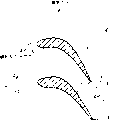
As shown in figure 11, middle connection set 11 comprises the 9c of back separately that is positioned at a blade live part 9a and blades adjacent live part 9b and pillar 11a and the 11b on 9d and belly 9e and the 9f.
Connecting sleeve 11c pivotally interconnects pillar 11a and 11b by the hangers (not shown) on the two ends that are arranged on pillar 11a and 11b.Therefore, be suppressed to less level such as the vibration of the intermediate portion that factor caused of overtime the fluctuation of jet pressure of the turbine drives steam that comes from turbine nozzle vane 3 stream and the vibration of turbine shaft.
As shown in figure 12, blade tip connection set 10 makes the end of turbine rotation blade 4 stable, and this blade tip connection set 10 forms tabular extension piece 10a and 10b as so-called " buffering type ", and tabular extension piece 10a and 10b integrally cut down from blade live part 9.In running, utilize the friction that is in contact with one another of extension piece 10a and 10b to suppress the blade tip vibration.
The said structure of middle connection set 11 and blade tip connection set 10 provides effective vibration proof countermeasure in having the turbine of linear leaf, and this vibration is caused by the factor such as overtime variation of turbine drives steam jeting pressure.
But in the steam turbine that has linear leaf (shown in Figure 10) in the prior art, when the blade live part 9 of turbine rotation blade 4 surpasses 1m, owing to length of blade has produced many other problems.One of them problem is: in running, because action of centrifugal force makes the warp architecture distortion of blade, so throat's blde pitch changes than (S/T), and its result causes power to reduce.
So-called by adopting " simplifying the three dimendional blade design method " experimentizes in the prior art and solves this problem.In this method, the channel height before and after turbine stage at first increases.Then, when the pressure ratio before and after the turbine stage was relatively large, the shape of cross section of turbine rotation blade changes so that adapt with such fact: constant speed figure improved along the channel height direction.
But, if the turbine rotation blade 4 of steam turbine is longer, as shown in figure 13, the turbine drives vapor phase to turbine blade the inflow angle will along blade live part 9 from the blade root to the average blade ring diameter (blde pitch circle diameter), change widely to blade tip.
In Figure 13, α represents that turbine drives steam flows into the inflow angle of turbine rotation blade 4, BV represents that the turbine drives steam that flows to turbine rotation blade 4 flows into velocity vector, SV represents that the turbine drives steam that flows out the turbine nozzle vane (not shown) flows out velocity vector, and U represents peripheral velocity.Equally, subscript R, P and T represent corresponding blade root, average blade ring diameter (blde pitch circle diameter) and blade tip position.
In this case, need the leaf cross-section shape at blade root, average blade ring diameter and each place, blade tip position of improvement blade live part 9, thereby make it and each locational turbine drives steam inflow angle [alpha]
R, α
PAnd α
TAdapt.But as prerequisite is at first to need to find each locational turbine drives steam to flow into velocity vector BV
R, BV
PAnd BV
T
Each locational turbine drives steam flows into velocity vector BV
R, BV
PAnd BV
TCan find from constant speed figure, this constant speed figure is by the rate of outflow SV of the turbine drives steam that flows out from the position of blade root, average blade ring diameter and the blade tip of turbine nozzle vane
R, SV
PAnd SV
TAnd the peripheral velocity vector that radius and angular velocity of rotation determined (circumferential speed component of turbine shaft) on each position (angular velocity of rotation of process is a constant, and is irrelevant with radial position) is formed.
Flow into velocity vector BV for the turbine drives steam on the diverse location that from constant speed figure, finds
R, BV
PAnd BV
T, flowing into angle can change.For example, the inflow angle [alpha] at blade root place
RGeneral in 30 ° to 50 ° scope, and the inflow angle [alpha] at blade tip place
TGeneral in 140 ° to 170 ° scope, and their angle difference can reach 140 ° when maximum.This be due to the fact that than the big difference angle due to: the radial distance of blade tip and blade spin axis is the twice of the radial distance of blade root and blade spin axis at least, correspondingly, the circumferential speed component of blade tip is the twice of the circumferential speed component of blade root at least.
If do not improve the change amount that the turbine rotation blade compensates this bigger inflow angle radially, will increase power loss significantly so.Therefore, each the locational turbine drives steam that makes it be suitable for blade live part 9 by the distortion angle that changes leaf cross-section flows into angle [alpha]
R, α
PAnd α
TThereby, improve steam turbine of the prior art; And, change leaf cross-section shape near leading edge along the inflow velocity direction vector.
Figure 14 is formed in the circumferencial direction cross-sectional view at any height place of the turbine rotor blade row on the plane, and shows the structure of turbine rotation blade stream passageway.S is a throat, and expression is formed on the width of the narrowest part of intra vane stream passageway between the belly of the back of a blade and next turbine rotation blade.T is a blde pitch, and it is the gap between the turbine rotation blade of along the circumferential direction going up.Throat's blde pitch is not rely on the power design parameter of steam turbine size and adapt with the outflow angle of turbine rotation blade than (S/T).In other words, if increase throat's blde pitch than (S/T), turbine rotation blade outflow angle becomes bigger so, and when the blade rate of outflow during as constant, the axial flow velocity component becomes bigger and this cross section flow velocity increases, and this turbine rotation blade flows out angle circumferencial direction is defined as 0.On the contrary, if reduce throat's blde pitch than (S/T), turbine rotation blade outflow angle becomes littler so, and the flow velocity of this cross section reduces.Throat's blde pitch of turbine nozzle vane is also more identical than the definition of (S/T).
In the chip level that comes into leaves, as the final stage of turbine, this not only limits radially big different circumferencial direction speed, pressure difference between inwall side (blade root) and the outer wall side (blade tip) becomes bigger, this pressure difference originates from the gradient of pressure, because the tangential velocity component that turbine nozzle vane produces, so this pressure rises on the exit position of turbine nozzle vane.In the design of the chip level that comes into leaves, need to adopt and considered that throat's blde pitch of this pressure difference distributes than (S/T).
Figure 15 is the example that the common turbine rotation blade throat blde pitch that adopts distributes than (S/T) in the prior art design.In " three-dimensional design method of simplification " of prior art, because it is difficult to estimate exactly the three-dimensional loss of each leaf cross-section, the design of generation makes that radially the velocity flow profile of per unit annulus area all approximately becomes constant to turbine nozzle vane and turbine rotation blade.For the turbine rotation blade, replacing approximately is the outlet static pressure distribution of constant, and the flow velocity of outer wall side has increased, and the inflow static pressure of outer wall side is higher.Therefore, adopt such design,, also improve axial flow velocity than (S/T) by the throat's blde pitch that improves the inwall side except reducing the axial flow velocity than (S/T) by the throat's blde pitch that reduces outer wall side, on the contrary, it is less and the turbine rotation blade rate of outflow is less to flow into static pressure.Therefore Radial Flow distributes and becomes approximately evenly.
With regard to the prior art turbine rotation blade of design by this way, when blade height hour no problem.But with regard to blade height surpasses the linear leaf of 1m, have such problem: be difficult to guarantee fully the pressure difference between the front and rear of blade root cross section of turbine rotation blade, this pressure difference is identical with the relevant pressure reduction of inflow static pressure.This will cause decreased performance.Simultaneously, owing to pass through same traffic at blade root cross section and other cross section, also have such problem: the overall power performance of turbine stage reduces.
Figure 16 represents that throat's blde pitch of prior art turbine nozzle vane distributes than (S/T).With regard to turbine nozzle vane, opposite with the turbine rotation blade, total pressure is opposite with flowing into approximately uniformly, and the outlet static pressure distributes and have the distribution of rising from the inboard to the outside.With regard to " simplify three-dimensional dimension design method " of prior art, distribute owing to be difficult to prediction loss radially, so it is flow distribution radially uniformly as a prerequisite.Because therefore this reason has adopted throat's blde pitch shown in Figure 16 to distribute than (S/T), this throat's blde pitch distributes than (S/T) and rises consistently from the blade root to the blade tip.
The problem of distribution shown in Figure 16 is: because the outflow angle of blade root becomes more and more littler, therefore the loss on this part has increased.Equally, there is a problem to be:, thereby to increase loss by the auxiliary flow turbulent flow that on the turning between wall and the turbine nozzle vane, produces along with the close wall of blade tip.Because as also flowing through this zone at the identical flow of other leaf area, the overall power performance of turbine stage reduces.
Figure 17 represents the radially direct of the power loss of prior art turbine nozzle vane.At the blade root sidepiece, by being diminished than (S/T), throat's blde pitch reduces to flow out angle, therefore produced vicious circle, promptly the rate of outflow improves greatly more, and loss increases manyly so.
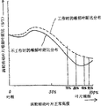
Therefore, desirable target is to have considered to change the effect and because the comprehensive three-dimensional dimension design method of the deformable blade effect that centrifugal force produced of flow distribution along the circumferential direction.But the prior art solution does not solve all problems up to now.Referring now to Figure 14 and 15 such solution is described.One row turbine rotation blade designs by this way: leading edge twists from the blade root to the blade tip along clockwise direction.Therefore, when on the live part 9 of tension that centrifugal force causes, produced anti-twist (untwisting) along arrow A R direction shown in Figure 14 at blade.Correspondingly, as shown in figure 15, although be arranged to the distribution shown in the solid line from the blade root to the blade tip when not working, it becomes the distribution shown in the dotted line to throat's blde pitch of turbine rotation blade 4 in theory in the course of the work than (S/T).But, the measure (being middle connection set 11 on the intermediate portion of blade live part 9 and the end connecting device 10 on the blade tip) that is used for controlling turbine rotation blade vibration has limited blade and has untwisted on these link positions, and the throat's blde pitch on the 70-95% height outwards expands than (S/T) distribution and has become a wider passages as shown in figure 15, and the height of 70-95% is under normal circumstances between connection set 10 and 11.
This situation can cause other problem.Under the situation of linear leaf turbine rotation blade 4, at the blade root diameter is the place that 1.4m or bigger and blade live part 9 surpass 1m, the identical speed (the seat seat by the setting of turbine rotation blade is to define this speed) of leaving the motion steam of turbine rotation blade is at least at the average diameter (PCD: the blde pitch circle diameter) surpass the speed of sound in the zone of blade tip, and it is mobile to become supersonic speed from blade live part 9.
As shown in figure 13, provide turbine drives steam and flow into the scope of angle along blade live part 9, if above-mentioned dilation is created in throat's blde pitch in the normal blade height zone of 75-95% than in (S/T) distribution, flow will overinflation for the supersonic speed of turbine drives steam so, thereby produces strong seismic wave on the leading edge of turbine rotation blade.
Therefore the steam turbine of prior art has many shortcomings.Their adopt and to produce radially almost uniformly that throat's blde pitch of Flow Distribution distributes than (S/T), consequently near the wall place on the blade root of turbine rotation blade and bigger near the frictional loss of the outer wall of turbine nozzle vane end.They also are subjected to by supersonic speed vapor stream and the expansion blade-section caused seismic wave that interacts, and this expansion blade-section is owing to blade untwists between the qualifying part that is created in blade live part 9.These shortcomings have hindered the operation of turbine according to design standard.
Summary of the invention
An object of the present invention is to provide a kind of steam turbine that is used for improving turbine blade row performance.
Another object of the present invention provides a kind of turbine rotation blade, and this turbine rotation blade makes turbine drives steam flow with stable status, thereby improves the performance of turbine.
Another object of the present invention provides a kind of turbine nozzle vane, and this turbine nozzle vane makes turbine drives steam with steady state flow, thereby improves the performance of turbine.
In order to realize these purposes, three dimendional blade design method designed for turbine rotation blade of the present invention and that adopt is such: this design method is regarded turbine drives steam as three-dimensional air-flow, and can control this three-dimensional air-flow.Therefore, more accurate than the three dimendional blade design method of the simplification of using prior art.
In other words, in the turbine blade row, throat's blde pitch of skew turbine rotation blade is than (S/T) before work.Blade produces when untwisting in the course of the work, by means of keeping desired value to prevent the overexpansion stream in supersonic speed zone than (S/T) distribution to form the throat's blde pitch that adapts with turbine drives steam inflow angle.
Simultaneously, radially given Flow Distribution, so that for turbine rotation blade and turbine nozzle vane, the turbine drives vapor stream reduces near the zone of wall, in this zone otherwise the loss bigger, and on the other hand, the turbine drives vapor stream increases in away from the zone of wall, and is less in this zone internal loss.
Description of drawings
Can be easy to receive and understand the present invention better and more fully be worth the many advantages that had with it in conjunction with the accompanying drawings and with reference to following detailed.
Fig. 1 is an embodiment's of an expression steam turbine of the present invention show in schematic partial sections.
Fig. 2 is the loss distribution map of turbine rotation blade assembly of the present invention.
Fig. 3 stacks planimetric map, the sectional view of each blade that its expression the present invention intercepts on the arbitrary position of turbine rotation blades height from the blade root to the blade tip.
Fig. 4 distributes than (S/T) with the static throat blde pitch of prior art and the throat's blde pitch during work distributes than (S/T) than (S/T) distribute static throat blde pitch of the turbine rotation blade of the present invention of comparing.
Fig. 5 be throat's blde pitch than (S/T) distribution map, it represents that the static throat blde pitch of blade height of the blade height to 50% of turbine rotation blade of the present invention from 0% is than (S/T).
Fig. 6 be throat's blde pitch than (S/T) distribution map, during its turbine rotation blade working relatively more of the present invention and when not working from throat's blde pitch of the blade height of 0% blade height to 100% than (S/T).
Fig. 7 be throat's blde pitch than (S/T) distribution map, it represents that throat's blde pitch of blade height of the blade height to 100% of turbine nozzle vane of the present invention from 0% is than (S/T).
Fig. 8 is a turbine stage loss distribution map, and throat's blde pitch at the blade root place of its expression turbine nozzle vane of the present invention is than the relation between (S/T) and the turbine stage loss.
Fig. 9 is a turbine stage loss distribution map, and throat's blde pitch at the blade tip place of its expression turbine nozzle vane of the present invention is than the relation between (S/T) and the turbine stage loss.
Figure 10 represents the turbine nozzle vane of last turbine stage and the constructed profile map of turbine rotation blade.
Figure 11 is the schematic representation of the middle connection set of looking from the arrow 11-11 direction of Figure 10.
Figure 12 is the signal oblique drawing of the blade tip connection set of looking from the arrow 12-12 direction of Figure 10.
Figure 13 is the schematic representation that is illustrated in the constant speed figure of the turbine drives steam that each position of blade root, average blade ring diameter and blade tip of the turbine rotation blade of final stage flows into.
Figure 14 represents the sectional view of the local improvement of the blade row of the turbine rotation blade of last turbine stage.
Figure 15 be throat's blde pitch than (S/T) distribution map, it compares than (S/T) than (S/T) and throat's blde pitch during operation turbine rotation blade throat's blde pitch when not working of last turbine stage.
Figure 16 be throat's blde pitch than (S/T) distribution map, its expression throat's blde pitch of the turbine nozzle vane of last turbine stage than (S/T).
Figure 17 is the loss distribution map of the turbine nozzle vane of last turbine stage.
Embodiment
With reference to the accompanying drawings with accompanying drawing in shown in label describe turbine rotation blade and turbine nozzle vane be assembled to preferred embodiment on the turbine relevant with the present invention.
In the steam turbine relevant with present embodiment, as shown in Figure 1, turbine stage 22 is made up of turbine nozzle vane assembly 20 and turbine rotation blade assembly 21, turbine nozzle vane assembly 20 ends are supported by internal fixation impeller 23 and outer fixing impeller 24, and turbine rotation blade assembly 21 embeds in the turbine shaft 25.Be provided with several this turbine stage 22 along turbine shaft 25.
Blade is made by alloy, and titanium is that 88-92%, aluminium are that 4-8% and vanadium are 2-6% by weight percentage in this alloy.Use the rotational speed of 3000rpm in the 50hz zone, use the rotational speed of 3600rpm in the 60hz zone.
Each turbine rotation blade 21 has blade embedded part 26 and blade live part 27.And each turbine rotation blade 21 blade tip is provided with blade tip connection set 28 and connection set 29 in the middle of the intermediate portion of blade is provided with.
The blade root diameter of blade live part 27 is 1.4m or bigger, and blade height is 1.0m or higher.
Middle connection set 29 is installed on the position in 50% to 70% scope of normal blade height, middle connection set 29 is used for reducing the vibration of duration of work turbine rotation blade 21, simultaneously any untwisting of turbine rotation blade 21 is minimized.This blade tip connection set 28 and middle connection set 29 are identical with Figure 11 and structure shown in Figure 12 separately, and are described above the figure with reference to these.
With reference to Fig. 3, because turbine rotation blade 21 is subjected to this designing requirement and has this blade row performance profile, therefore the air-flow Three-dimensional Flow pattern of turbine blade row can be carried out preferably than (S/T) by suitable throat's blde pitch is set, wherein T represents the blde pitch between a blade live part 27a and the blades adjacent live part 27b, and S represents the width (the narrowest passage) by the formed mobile throat of belly of the back 30 of a blade live part 27a and blades adjacent live part 27b.
In Fig. 3, when from the blade root to the blade tip when blade height goes up the intercepting leaf cross-section at an arbitrary position (as, A
0Expression is positioned at the leaf cross-section at blade root place (blade height is 0%), A
15Expression is positioned at the leaf cross-section at blade height 15% place, A
30Expression is positioned at the leaf cross-section at blade height 30% place, A
85Expression is positioned at the leaf cross-section at blade height 85% place, and A
100Expression is positioned at the leaf cross-section of blade tip place (blade height 100%)), then, if make each cross section A
0, A
15... distortion angle big than prior art, each outlet limit 31,31 ... the outlet of the prior art limit crown line TERL (with dashed lines is represented) that couples together moves to and departs from outlet limit crown line OTERL (representing with solid line).
In fact, given along clockwise direction distortion angle is so that cross section A
0From position P
0Move to position Q
0, cross section A
15From position P
15Move to position Q
15And cross section A
85From position P
85Move to position Q
85, same, given in the counterclockwise direction distortion angle is so that cross section A
30From position P
30Move to position Q
30With cross section A
100From position P
100Move to position Q
100Form the leading edge crown line OLERL that is offset by solid line, this solid line is each cross section A
0, A
15Leading edge 32,32 ... couple together.When look and simultaneously when look in the back that makes progress each cross section A from the leading edge on the left side
0, A
30Given distortion angle be clockwise direction or counterclockwise.
If realize skew by distortion angle is set as mentioned above, throat's blde pitch has the distribution shown in Fig. 4 solid line than (S/T) when not working so, and having the distribution shown in the dotted line during operation, this throat's blde pitch is decided by the distance between the turbine rotation blade than (S/T).
If each cross section A
0, A
15Given leaf curling angle is bigger than prior art, and each cross section A
0, A
15Throat's blde pitch decide according to the leaf curling angle than (S/T), the throat's blde pitch shown in Fig. 4 solid line distribute to form the roughly S-shaped curve with maximum value and minimum value than (S/T) so.Simultaneously, solid line is offset significantly uses the shown throat of the prior art of single-point dot and dash line blde pitch than (S/T) position, and we can say the maintenance skew.
By this way, to this embodiment, by giving each cross section A in advance
0, A
15A distortion angle bigger than prior art decides throat's blde pitch than (S/T), and (S/T) that should determine is displaced on the position shown in the solid line.This difference distortion angle (compared with prior art) is defined as " difference leaf curling angle " here.
Along with untwisting of being produced in the course of the work, should (S/T) distribute and remove and more consistent than (S/T) position with the throat's blde pitch shown in the dotted line from deviation post.Therefore, make more turbine drives steam in the less zone of loss, flow, and make few turbine drives steam in the bigger zone of loss, flow, consequently improved the performance of turbine blade row.
Throat's blde pitch of turbine rotation blade 21 shown in Figure 4 is such figure than (S/T) distribution map: in the figure, difference leaf curling angle is arranged on all leaf cross-section A0, A15 of the whole blade from the blade root to the blade tip ... on.But, whether depend on whether the turbine drives vapor stream is subsonic or transonic providing difference leaf curling angle on the whole length of blade or on the smaller portions at blade.
When the turbine drives vapor stream is subsonic speed or transonic speed, for turbine rotation blade 21, as shown in Figure 5, throat's blde pitch decides by giving the given difference distortion angle of each leaf cross-section than (S/T), and each leaf cross-section here to be positioned at blade root (blade height 0%) be 10% to 45% blade height scope of reference, and predetermined throat's blde pitch distributes to form than (S/T) and has at least one minimum value or peaked curve, perhaps forms to have a minimum value and a peaked so-called sigmoid curve.In fact, preferably throat's blde pitch is formed on the interior blade height position of 10-20% scope than the minimum value of (S/T), and throat's blde pitch is preferably formed on the blade height position in the 15-45% scope than the maximum value of (S/T), and is preferably formed on the blade height position in the 25-35% scope.
Be scheduled to throat's blde pitch than (S/T) by giving a difference leaf curling of each cross section angle in 10-45% blade height scope, and throat's blde pitch is arranged to above-mentioned having at least one minimum value or peaked curve or have a minimum value and a peaked sigmoid curve than (S/T) distribution curve, thereby the blade that compensation produces in the course of the work untwists and simultaneously in the less zone of turbine rotation blade loss by more turbine drives steam, as shown in Figure 2, therefore improved the performance of turbine blade row.But especially will to 10% or littler blade height position on a given difference leaf curling angle noted.
Specifically, if throat's blde pitch is located less than (S/T) at the wall (turbine shaft) near blade root, flow out angle so and become littler and improve owing near the turbulent flow the blade root of the corner between blade and the embedded part makes the auxiliary flow loss, the root fillet of corner increases in order to reduce stress to concentrate.For preventing that the actual throat blde pitch that comprises root fillet from becoming too little than (S/T), be necessary that the leaf curling angle of adjusting root fillet makes throat's blde pitch bigger than (S/T).
When turbine drives steam flows with supersonic speed, for turbine rotation blade 21, as shown in Figure 6, adopting above-mentioned identical mode is reference with the blade root, throat's blde pitch is decided by the given difference leaf curling angle of each leaf cross-section than (S/T), and each leaf cross-section here is positioned at 10% to 95% blade height scope.Therefore predetermined throat's blde pitch distributes than (S/T) and has a minimum value and a peaked sigmoid curve in the blade height scope that is formed on 10-95%, and predetermined throat's blde pitch distributes simultaneously than (S/T) and is offset on 70-95% preferably has the curve of minimum value in the blade height scope at 80-90%.This STRUCTURE DEPRESSION the dilation (Figure 15 illustrates) that produced when turning on the contrary of duration of work blade, and guarantee that the turbine drives flow of steam remains on steady state, therefore suppressed the generation of seismic wave.
Further improving turbine efficiency on the linear leaf turbine can realize by a difference leaf curling of the leaf cross-section angle of given turbine nozzle vane 20.Therefore the vapor stream that flows out from turbine nozzle vane will match with the turbine rotation blade more effectively with their power form.As shown in figure 14, define throat's blde pitch of turbine nozzle vane than (S/T) in the mode identical with (S/T) of turbine rotation blade 4.
As shown in Figure 7, when consideration distributes than (S/T) from blade root (blade height 0%) to this throat blde pitch of blade tip (blade height 100%) on the blade height direction, getting blade root is reference, and it seems in the blade height scope of 20-80% and outwards expand, seems to have formed maximum value.Here, for turbine nozzle vane 20, the internal fixation impeller 23 that blade root is contiguous shown in Figure 1, and the contiguous outer fixing impeller 24 of blade tip.
Throat's blde pitch than this distribution of (S/T) by the given difference leaf curling of cross section angle is produced, seem in the blade height scope of 20-80%, to form maximum value, and respectively throat's blde pitch of blade root (blade height 0%) is arranged in 0.1 to 0.5 scope than (S/T), throat's blde pitch of blade tip (blade height 100%) is arranged in 0.14 to 0.5 scope than (S/T).
Therefore, reduced total losses (the turbine nozzle vane loss adds turbine rotation blade loss).
Throat's blde pitch of 0.1-0.5 shown in Figure 8 is the most preferably application area that obtains from the model turbine than (S/T).If throat's blde pitch of blade root and blade tip is too littler than (S/T), owing to adopt this value as the border, auxiliary (turbulent flow) flow losses of close wall increase fast, therefore adopt above-mentioned value to make loss increase fast as the border.And the flow distribution balance of passing is radially upset, thereby causes excessive flow and the quick increase that causes frictional loss at close wall place at the wall place.
According to the fact that turbine stage loss shown in Figure 9 becomes more and more littler throat's blde pitch of blade tip (blade height 100%) is arranged to 0.14-0.5 than (S/T).Throat's blde pitch of blade tip is preferred application area than this scope of (S/T), and obtains from the model turbine equally.
Summarize this embodiment, throat's blde pitch of turbine nozzle vane 20 is by the given difference leaf curling angle of leaf cross-section is determined than (S/T), so that throat's blde pitch seems to have formed maximum value than outwards expanding in the blade height scope that is distributed in 20-80% of (S/T).Simultaneously, throat's blde pitch of blade root (blade height 0%) is arranged in the 0.1-0.5 scope than (S/T), and throat's blde pitch of blade tip (blade height 100%) is arranged in the 0.14-0.5 scope than (S/T).Therefore, more turbine drives steam concentrated and be flowing in the turbine stage loss less the zone in.Therefore, turbine blade row performance relatively prior art further improve.
For turbine nozzle vane, be to adjust the direct method of throat's blde pitch although adjust the leaf curling angle than (S/T), can also assign to adjust throat's blde pitch than (S/T) to the curved part that exports the limit by changing from the part that forms back throat.In other words, if make the part that forms back throat littler to the curved section on outlet limit, the outlet limit will be more near the back of blades adjacent, and throat's blde pitch will become littler than (S/T).On the contrary, if make curved section bigger, throat's blde pitch will become bigger than (S/T).In addition, can adjust throat's blde pitch than (S/T) by the thickness that changes the outlet limit.But, owing to make outlet limit thickening will reduce the blade row performance, so need carry out other and adjust and keep general effect.
In a word, for being assemblied in the turbine rotation blade in the steam turbine of the present invention, for the blade that produces in the compensation work process untwists, distribution than (S/T) is offset according to throat's blde pitch of determining for the given difference leaf curling angle of leaf cross-section, bigger than prior art so that it becomes, and therefore throat's blde pitch remains on optimum value than (S/T) in the course of the work.Therefore, turbine drives steam flows with stable status more, and has improved turbine blade row performance.
For turbine nozzle vane, expand along outside direction than the distribution of (S/T) according to throat's blde pitch of determining for the given difference leaf curling angle of leaf cross-section, seem to have formed maximum value.Therefore, more turbine steam is concentrated and is flowing in the less zone of turbine stage loss.Therefore, turbine blade row performance relatively prior art further improve.
Obviously, can carry out many modifications and change to the present invention according to top description.
The PH10-218262 Japan that on July 31st, 1998 proposed is hereby incorporated by document at specification, accompanying drawing, claims and the summary of first to file.
Claims (16)
1. the turbine rotation blade assembly of a steam turbine, it has a plurality of levels, every grade is provided with turbine rotation blade and the fixing turbine nozzle vane that is installed on the turbine shaft, the contiguous vertically turbine rotation blade installation of turbine nozzle vane, the turbine rotation blade is along the circumferential direction spaced apart with contiguous turbine rotation blade, contiguous turbine rotation blade is connected with each other in neutral position of their ends and their radial outer end portion, each turbine rotation blade is twisted from the blade root to the blade tip, it is characterized in that, distortion angle difference along the leaf cross-section of each turbine rotation blade height, distribute than S/T along the throat blde pitch of turbine rotation blade height direction from the blade root to the blade tip thereby produce, this throat's blde pitch forms one than the S/T distribution and has at least one minimum value and a peaked curve.
2. turbine rotation blade assembly as claimed in claim 1 is characterized in that, considers the steam turbine duration of work because the turbine rotation blade that centrifugal action produces untwists, and described throat blde pitch distributes than S/T and is offset.
3. turbine rotation blade assembly as claimed in claim 1 or 2 is characterized in that, maximum value is positioned at about 15% to 45% turbine rotation blade height scope.
4. turbine rotation blade assembly as claimed in claim 3 is characterized in that, described minimum value is positioned at 10% to 20% turbine rotation blade height scope, and maximum value is positioned at 25% to 35% blade height scope of turbine rotation blade.
5. turbine rotation blade assembly as claimed in claim 1 or 2 is characterized in that, minimum value is positioned at 70% to 95% turbine rotation blade height scope.
6. turbine rotation blade assembly as claimed in claim 3 is characterized in that, minimum value is positioned at 70% to 95% turbine rotation blade height scope.
7. turbine rotation blade assembly as claimed in claim 1 or 2 is characterized in that, a part of difference leaf curling angle is given along clockwise direction to leaf cross-section, and another part difference leaf curling angle is given in the counterclockwise direction to leaf cross-section.
8. turbine rotation blade assembly as claimed in claim 7, it is characterized in that, given along clockwise direction difference leaf curling angle is positioned at approximately on the position of from 0% to 85% turbine rotation blade height scope, and given in the counterclockwise direction difference leaf curling angle is positioned at from about 30% blade height position to about 100% blade height position.
9. turbine rotation blade assembly as claimed in claim 1 or 2 is characterized in that the root diameter (RD) of turbine rotation blade assembly is at least 1.4m, and the turbine rotation blades height is at least 1.0m, and turbine shaft is with 3000rpm or 3600rpm rotation.
10. turbine rotation blade assembly as claimed in claim 1 or 2, it is characterized in that, described turbine rotation blade is made by titanium alloy, and this titanium alloy is made up of about titanium of 88% to 92%, about aluminium of 4% to 8% and about vanadium of 2% to 6% according to weight percentage.
11. turbine rotation blade assembly as claimed in claim 1 or 2 is characterized in that, connects about 50% to 70% the turbine rotation blade height scope that is positioned in the middle of the turbine rotation blade.
12. turbine rotation blade assembly as claimed in claim 1 is characterized in that, adopts turbine rotation blade difference distortion angle at least one turbine stage of the most last turbine stage and the most last turbine upstream.
13. the turbine nozzle vane assembly of a steam turbine, it has a plurality of levels, every grade is provided with turbine rotation blade and the fixing turbine nozzle vane that is installed on the turbine shaft, the contiguous vertically turbine rotation blade installation of turbine nozzle vane, each turbine nozzle vane is twisted from the blade root to the blade tip, it is characterized in that, distortion angle difference along the leaf cross-section of each turbine nozzle vane height, distribute than S/T along the throat blde pitch of turbine nozzle vane short transverse from the blade root to the blade tip thereby produce, this throat's blde pitch forms one than the S/T distribution and has at least one peaked curve, and this maximum value is positioned at about 20% to 80% turbine nozzle vane altitude range.
14. turbine nozzle vane assembly as claimed in claim 13 is characterized in that, described maximum value is positioned at about scope of 0.1 to 0.5 and is positioned at about scope of 0.14 to 0.5 in the blade tip position in the blade root position.
15. turbine nozzle vane assembly as claimed in claim 13 is characterized in that, adopts turbine nozzle vane difference distortion angle at least one turbine stage of the most last turbine stage and the most last turbine upstream.
16. in the steam turbine, it has a housing, rotatable axle and some levels in housing, every grade is provided with turbine rotation blade and the fixing turbine nozzle vane that is installed on the turbine shaft, the contiguous vertically turbine rotation blade installation of turbine nozzle vane, the turbine rotation blade is along the circumferential direction spaced apart with contiguous turbine rotation blade, contiguous turbine rotation blade is connected with each other in neutral position of their ends and their radial outer end portion, each turbine rotation blade is twisted from the blade root to the blade tip, it is characterized in that, distortion angle difference along the leaf cross-section of each turbine rotation blade height, distribute than S/T along the throat blde pitch of turbine rotation blade height direction from the blade root to the blade tip thereby produce, this throat's blde pitch forms one than the S/T distribution and has at least one minimum value and a peaked curve.
Applications Claiming Priority (2)
| Application Number | Priority Date | Filing Date | Title |
|---|---|---|---|
| JP218262/1998 | 1998-07-31 | ||
| JP10218262A JP2000045704A (en) | 1998-07-31 | 1998-07-31 | Steam turbine |
Publications (2)
| Publication Number | Publication Date |
|---|---|
| CN1243910A CN1243910A (en) | 2000-02-09 |
| CN1239810C true CN1239810C (en) | 2006-02-01 |
Family
ID=16717124
Family Applications (1)
| Application Number | Title | Priority Date | Filing Date |
|---|---|---|---|
| CNB991110692A Expired - Lifetime CN1239810C (en) | 1998-07-31 | 1999-07-30 | High effective blade structure of turbine |
Country Status (6)
| Country | Link |
|---|---|
| US (3) | US6375420B1 (en) |
| EP (1) | EP0985801B1 (en) |
| JP (1) | JP2000045704A (en) |
| KR (1) | KR100362833B1 (en) |
| CN (1) | CN1239810C (en) |
| DE (1) | DE69920358T2 (en) |
Families Citing this family (42)
| Publication number | Priority date | Publication date | Assignee | Title |
|---|---|---|---|---|
| JP2000045704A (en) * | 1998-07-31 | 2000-02-15 | Toshiba Corp | Steam turbine |
| JP4373629B2 (en) * | 2001-08-31 | 2009-11-25 | 株式会社東芝 | Axial flow turbine |
| US6682301B2 (en) * | 2001-10-05 | 2004-01-27 | General Electric Company | Reduced shock transonic airfoil |
| EP1462610A1 (en) * | 2003-03-28 | 2004-09-29 | Siemens Aktiengesellschaft | Rotor blade row for turbomachines |
| US7312149B2 (en) * | 2004-05-06 | 2007-12-25 | Taiwan Semiconductor Manufacturing Co., Ltd. | Copper plating of semiconductor devices using single intermediate low power immersion step |
| EP1612372B1 (en) * | 2004-07-01 | 2014-10-08 | Alstom Technology Ltd | Turbine blade with a cut-back at the root of the blade |
| CN100339559C (en) * | 2005-07-31 | 2007-09-26 | 东方电气集团东方汽轮机有限公司 | Last stage rotor blade of steam turbine |
| US20090214345A1 (en) * | 2008-02-26 | 2009-08-27 | General Electric Company | Low pressure section steam turbine bucket |
| DE102008031781B4 (en) * | 2008-07-04 | 2020-06-10 | Man Energy Solutions Se | Blade grille for a turbomachine and turbomachine with such a blade grille |
| US8075272B2 (en) * | 2008-10-14 | 2011-12-13 | General Electric Company | Steam turbine rotating blade for a low pressure section of a steam turbine engine |
| US8313292B2 (en) * | 2009-09-22 | 2012-11-20 | Siemens Energy, Inc. | System and method for accommodating changing resource conditions for a steam turbine |
| US20110097205A1 (en) * | 2009-10-28 | 2011-04-28 | General Electric Company | Turbine airfoil-sidewall integration |
| ITMI20101447A1 (en) * | 2010-07-30 | 2012-01-30 | Alstom Technology Ltd | "LOW PRESSURE STEAM TURBINE AND METHOD FOR THE FUNCTIONING OF THE SAME" |
| US8790082B2 (en) | 2010-08-02 | 2014-07-29 | Siemens Energy, Inc. | Gas turbine blade with intra-span snubber |
| EP2479381A1 (en) * | 2011-01-21 | 2012-07-25 | Alstom Technology Ltd | Axial flow turbine |
| WO2012119662A1 (en) * | 2011-03-07 | 2012-09-13 | Multi-Wing International A/S | An engine cooling fan |
| JP5868605B2 (en) * | 2011-03-30 | 2016-02-24 | 三菱重工業株式会社 | gas turbine |
| US8777564B2 (en) | 2011-05-17 | 2014-07-15 | General Electric Company | Hybrid flow blade design |
| US8967959B2 (en) * | 2011-10-28 | 2015-03-03 | General Electric Company | Turbine of a turbomachine |
| US8992179B2 (en) | 2011-10-28 | 2015-03-31 | General Electric Company | Turbine of a turbomachine |
| US9051843B2 (en) | 2011-10-28 | 2015-06-09 | General Electric Company | Turbomachine blade including a squeeler pocket |
| US9255480B2 (en) * | 2011-10-28 | 2016-02-09 | General Electric Company | Turbine of a turbomachine |
| US8998577B2 (en) * | 2011-11-03 | 2015-04-07 | General Electric Company | Turbine last stage flow path |
| EP2653658A1 (en) * | 2012-04-16 | 2013-10-23 | Siemens Aktiengesellschaft | Guide blade assembly for an axial flow machine and method for laying the guide blade assembly |
| US9157326B2 (en) | 2012-07-02 | 2015-10-13 | United Technologies Corporation | Airfoil for improved flow distribution with high radial offset |
| CN102926821A (en) * | 2012-11-07 | 2013-02-13 | 哈尔滨汽轮机厂有限责任公司 | 900mm last stage moving blade for combined cycle steam turbine |
| JP5836410B2 (en) * | 2014-02-27 | 2015-12-24 | 三菱重工業株式会社 | Rotor blade and rotating machine |
| JP6081398B2 (en) * | 2014-03-12 | 2017-02-15 | 株式会社東芝 | Turbine blade cascade, turbine stage and steam turbine |
| EP3023585B1 (en) * | 2014-11-21 | 2017-05-31 | General Electric Technology GmbH | Turbine arrangement |
| US10323528B2 (en) * | 2015-07-01 | 2019-06-18 | General Electric Company | Bulged nozzle for control of secondary flow and optimal diffuser performance |
| CN105499918B (en) * | 2015-12-03 | 2017-10-24 | 哈尔滨汽轮机厂有限责任公司 | A kind of supercritical pressure turbine pretwist type guide vane assembly method |
| US9963985B2 (en) * | 2015-12-18 | 2018-05-08 | General Electric Company | Turbomachine and turbine nozzle therefor |
| US9957805B2 (en) * | 2015-12-18 | 2018-05-01 | General Electric Company | Turbomachine and turbine blade therefor |
| US9957804B2 (en) * | 2015-12-18 | 2018-05-01 | General Electric Company | Turbomachine and turbine blade transfer |
| US10247006B2 (en) * | 2016-07-12 | 2019-04-02 | General Electric Company | Turbine blade having radial throat distribution |
| CN106256993A (en) * | 2016-08-09 | 2016-12-28 | 杭州汽轮机股份有限公司 | A kind of final stage moving blade of feed pump industrial steam turbine |
| US10502073B2 (en) * | 2017-03-09 | 2019-12-10 | General Electric Company | Blades and damper sleeves for a rotor assembly |
| DE102018211158A1 (en) * | 2018-07-06 | 2020-01-09 | MTU Aero Engines AG | Blade arrangement for a gas turbine and method for producing the blade arrangement |
| CN109578085B (en) * | 2018-12-26 | 2021-06-22 | 中国船舶重工集团公司第七0三研究所 | Method for weakening unsteady acting force of turbine movable blade through guide blade inclination |
| CN113994072A (en) * | 2019-06-14 | 2022-01-28 | 株式会社Ihi | Pressure booster |
| US11220910B2 (en) * | 2019-07-26 | 2022-01-11 | Pratt & Whitney Canada Corp. | Compressor stator |
| CN114483311A (en) * | 2021-12-31 | 2022-05-13 | 北京动力机械研究所 | Compact type double-medium air inlet structure |
Family Cites Families (20)
| Publication number | Priority date | Publication date | Assignee | Title |
|---|---|---|---|---|
| US2935246A (en) | 1949-06-02 | 1960-05-03 | Onera (Off Nat Aerospatiale) | Shock wave compressors, especially for use in connection with continuous flow engines for aircraft |
| CH557468A (en) * | 1973-04-30 | 1974-12-31 | Bbc Brown Boveri & Cie | TURBINE OF AXIAL DESIGN. |
| JPS614965A (en) | 1984-06-20 | 1986-01-10 | Hitachi Tokyo Electronics Co Ltd | Tachometer voltage generating device |
| GB2162587B (en) | 1984-07-30 | 1988-05-05 | Gen Electric | Steam turbines |
| US4643645A (en) | 1984-07-30 | 1987-02-17 | General Electric Company | Stage for a steam turbine |
| JPH01182504A (en) * | 1988-01-12 | 1989-07-20 | Mitsubishi Heavy Ind Ltd | Reforming method for surface of turbine blade |
| US5035578A (en) * | 1989-10-16 | 1991-07-30 | Westinghouse Electric Corp. | Blading for reaction turbine blade row |
| JPH03267506A (en) * | 1990-03-19 | 1991-11-28 | Hitachi Ltd | Stationary blade of axial flow turbine |
| US5221181A (en) * | 1990-10-24 | 1993-06-22 | Westinghouse Electric Corp. | Stationary turbine blade having diaphragm construction |
| JP2841970B2 (en) * | 1991-10-24 | 1998-12-24 | 株式会社日立製作所 | Gas turbine and nozzle for gas turbine |
| US5286168A (en) | 1992-01-31 | 1994-02-15 | Westinghouse Electric Corp. | Freestanding mixed tuned blade |
| US5203676A (en) | 1992-03-05 | 1993-04-20 | Westinghouse Electric Corp. | Ruggedized tapered twisted integral shroud blade |
| US5267834A (en) | 1992-12-30 | 1993-12-07 | General Electric Company | Bucket for the last stage of a steam turbine |
| JP3132944B2 (en) | 1993-03-17 | 2001-02-05 | 三菱重工業株式会社 | Three-dimensional design turbine blade |
| US5480285A (en) * | 1993-08-23 | 1996-01-02 | Westinghouse Electric Corporation | Steam turbine blade |
| US5326221A (en) * | 1993-08-27 | 1994-07-05 | General Electric Company | Over-cambered stage design for steam turbines |
| US5393200A (en) * | 1994-04-04 | 1995-02-28 | General Electric Co. | Bucket for the last stage of turbine |
| US5695323A (en) * | 1996-04-19 | 1997-12-09 | Westinghouse Electric Corporation | Aerodynamically optimized mid-span snubber for combustion turbine blade |
| JP3805461B2 (en) | 1997-02-12 | 2006-08-02 | 株式会社ダイゾー | Aerosol products |
| JP2000045704A (en) * | 1998-07-31 | 2000-02-15 | Toshiba Corp | Steam turbine |
-
1998
- 1998-07-31 JP JP10218262A patent/JP2000045704A/en active Pending
-
1999
- 1999-07-27 US US09/361,570 patent/US6375420B1/en not_active Expired - Lifetime
- 1999-07-29 DE DE69920358T patent/DE69920358T2/en not_active Expired - Lifetime
- 1999-07-29 EP EP99114881A patent/EP0985801B1/en not_active Expired - Lifetime
- 1999-07-29 KR KR1019990031063A patent/KR100362833B1/en not_active IP Right Cessation
- 1999-07-30 CN CNB991110692A patent/CN1239810C/en not_active Expired - Lifetime
-
2001
- 2001-12-26 US US10/025,597 patent/US6769869B2/en not_active Expired - Lifetime
- 2001-12-26 US US10/025,557 patent/US20020054817A1/en not_active Abandoned
Also Published As
| Publication number | Publication date |
|---|---|
| EP0985801A3 (en) | 2000-12-13 |
| US20020048514A1 (en) | 2002-04-25 |
| US6769869B2 (en) | 2004-08-03 |
| CN1243910A (en) | 2000-02-09 |
| KR100362833B1 (en) | 2002-11-30 |
| EP0985801A2 (en) | 2000-03-15 |
| US20020054817A1 (en) | 2002-05-09 |
| EP0985801B1 (en) | 2004-09-22 |
| DE69920358T2 (en) | 2006-02-23 |
| KR20000012075A (en) | 2000-02-25 |
| JP2000045704A (en) | 2000-02-15 |
| US6375420B1 (en) | 2002-04-23 |
| DE69920358D1 (en) | 2004-10-28 |
Similar Documents
| Publication | Publication Date | Title |
|---|---|---|
| CN1239810C (en) | High effective blade structure of turbine | |
| CN1272524C (en) | Turbomachine blade unit | |
| CA2658914C (en) | Impulse turbine for use in bi-directional flows | |
| US8764380B2 (en) | Rotor blade | |
| EP2492484A2 (en) | Propfan engine | |
| JP2001214893A (en) | Curved barrel aerofoil | |
| JP2001132696A (en) | Stationary blade having narrow waist part | |
| CN1368923A (en) | Rotor with split rotor blade | |
| CN1840857A (en) | Axial turbine | |
| JP4924984B2 (en) | Cascade of axial compressor | |
| WO2013014938A1 (en) | Propeller with small duct, and ship | |
| JP2011063258A (en) | Front flow fixed wing body with duct | |
| CN102673760A (en) | Pre-nozzle for a drive system of a water vehicle for improving energy efficiency | |
| KR101684367B1 (en) | Ducted Pre-Swirl Stator | |
| WO2023226366A1 (en) | Mixed-flow fan and air-duct type air conditioner | |
| CN112943686B (en) | Centrifugal compressor impeller and design method thereof | |
| JP2006207556A (en) | Turbine blade train | |
| JP3188128B2 (en) | Stator of vehicle torque converter | |
| JP2011021525A (en) | Turbine blade cascade, and turbine stage and axial flow turbine using the same | |
| CN108698687B (en) | Rotorcraft rotor blade for generating lift by autorotation | |
| CN1240931C (en) | Three-D axial-flow turbine stage | |
| CN1171021C (en) | Axial-flow fan and inclination changing blade axial-flow fan | |
| US11773819B2 (en) | Rotor blade for a wind turbine | |
| JP2005255104A (en) | Screw propeller | |
| JP4690702B2 (en) | Water wheel and control method thereof |
Legal Events
| Date | Code | Title | Description |
|---|---|---|---|
| C10 | Entry into substantive examination | ||
| SE01 | Entry into force of request for substantive examination | ||
| C06 | Publication | ||
| PB01 | Publication | ||
| C14 | Grant of patent or utility model | ||
| GR01 | Patent grant | ||
| CX01 | Expiry of patent term | ||
| CX01 | Expiry of patent term |
Granted publication date: 20060201 |