EP0985594A2 - Rear partial structure of monocoque vehicle body construction and its method of production - Google Patents
Rear partial structure of monocoque vehicle body construction and its method of production Download PDFInfo
- Publication number
- EP0985594A2 EP0985594A2 EP99115806A EP99115806A EP0985594A2 EP 0985594 A2 EP0985594 A2 EP 0985594A2 EP 99115806 A EP99115806 A EP 99115806A EP 99115806 A EP99115806 A EP 99115806A EP 0985594 A2 EP0985594 A2 EP 0985594A2
- Authority
- EP
- European Patent Office
- Prior art keywords
- side wall
- wall sections
- cross member
- cross
- flat component
- Prior art date
- Legal status (The legal status is an assumption and is not a legal conclusion. Google has not performed a legal analysis and makes no representation as to the accuracy of the status listed.)
- Granted
Links
- 238000004519 manufacturing process Methods 0.000 title claims description 12
- 238000000034 method Methods 0.000 title claims description 10
- 238000010276 construction Methods 0.000 title 1
- 238000005253 cladding Methods 0.000 claims description 2
- 238000009434 installation Methods 0.000 description 9
- 238000003466 welding Methods 0.000 description 6
- 230000002787 reinforcement Effects 0.000 description 3
- 230000000712 assembly Effects 0.000 description 2
- 238000000429 assembly Methods 0.000 description 2
- 239000011324 bead Substances 0.000 description 2
- 238000005304 joining Methods 0.000 description 2
- 239000002184 metal Substances 0.000 description 2
- FFBHFFJDDLITSX-UHFFFAOYSA-N benzyl N-[2-hydroxy-4-(3-oxomorpholin-4-yl)phenyl]carbamate Chemical compound OC1=C(NC(=O)OCC2=CC=CC=C2)C=CC(=C1)N1CCOCC1=O FFBHFFJDDLITSX-UHFFFAOYSA-N 0.000 description 1
- 238000007796 conventional method Methods 0.000 description 1
- 238000003860 storage Methods 0.000 description 1
- 238000011144 upstream manufacturing Methods 0.000 description 1
Images

Classifications
-
- B—PERFORMING OPERATIONS; TRANSPORTING
- B62—LAND VEHICLES FOR TRAVELLING OTHERWISE THAN ON RAILS
- B62D—MOTOR VEHICLES; TRAILERS
- B62D25/00—Superstructure or monocoque structure sub-units; Parts or details thereof not otherwise provided for
- B62D25/08—Front or rear portions
- B62D25/087—Luggage compartments
Definitions
- the invention relates to a rear structure of a self-supporting Motor vehicle body with two side wall sections, between those below a rear window cut-out are the side wall sections interconnecting transverse wall is arranged, which has two mutually spaced cross members, between which a flat component extends, and a method for the production of the rear structure.
- DE 196 18 258 A1 discloses a motor vehicle frame which is composed of several beams from extruded profiles.
- the Beams have flat contact areas that compensate for tolerances ensure in the longitudinal and transverse direction of the vehicle.
- DE 44 31 970 A1 discloses a motor vehicle body, at the one on a floor panel on opposite sides Body sheet is welded, which forms a wheel house.
- bottom plate has corresponding ones on its opposite sides Weld-on flanges, each with a bead are connected to the floor panel. This bead allows a deformation of the floor panel across the plane of the respective Welding flange.
- the object of the invention is a rear structure of the aforementioned Way and to create a process for their manufacture in which tension-free joining is made with the simplest possible means allows the transverse wall between the side wall sections is.
- the flat component represents in particular an interior part of the vehicle interior, in which speaker recordings or other additional functions are integrated.
- the first cross member is adjacent on the rear window cutout between the side wall sections fitted. About this cross member is first one exact positioning of the side wall sections against each other allows a place where a vehicle rear window is provided is.
- the second cross member is provided on both sides one bearing each adjustable between the side wall sections to arrange. This will compensate for manufacturing tolerances enables, so that the arrangement of side wall sections and cross beams stress-free and symmetrical can be aligned and then fixed.
- the flat component can also be positioned without tension Attach the cross member.
- Locking means in particular latch locks to determine a foldable Provide rear seat backrest on the second cross member and advantageously align with this.
- the flat component can function and thus also in its mass or its stability properties severely restrict, so that costs and vehicle weight let reduce.
- the flat component is attached to the positioned cross members, by suitable design of the flat component Positional tolerances of the cross beams easily compensated can be.
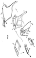
- FIG. 1 In the figures is a rear structure of a passenger car according to the invention shown that seen on the in the direction of travel left side is arranged.
- a mirror image regarding the vehicle longitudinal axis is part of the rear structure on the right-hand side of the passenger car as seen in the direction of travel arranged, but not shown in the drawings.
- the following explanations therefore refer to the shown left part of the rear structure, but are for the other part applies in the same way.
- the rear structure has one of several Divide existing side wall sections 1 to 5. in the individual, these components are an outer paneling 1 with a protruding weld-on part 2, an inner wall 3 of the C-pillar, an outer part 4 of the wheel installation and an inner part 5 of wheel installation.
- the components mentioned are more conventional Way to assemble a side wall section that over it with further side wall sections to a complete Vehicle side wall can be summarized.
- the inner wall 3 of the C-pillar protrudes an intermediate piece 7 inwards added. Furthermore, on the inside of the inner part 5 of the Wheel installation aligned in the direction of the vehicle vertical axis Reinforcement 6 arranged directly at the top in a Console 8 merges.
- the console 8 is on its outside oriented side with both the inner part 5 of the wheel installation as also connected to the inner wall 3 of the C-pillar. This is particularly so can be seen from the sectional view in FIG. 5.
- the Console 8 thus forms an upper end for the reinforcement 6, in the area of the wheel installation or the vehicle rear axle ensures a special stiffening of the vehicle body.
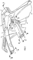
- Parcel shelf 10 and rear cross-member 10 11, 12 fitted which consist of the components rear center piece 10, front cross member 11 and panel 12 is composed.
- the rear center piece 10 serving as the first cross member is off assembled two sheet metal profiles 10a and 10b and has one 3 on cross section.
- the rear center piece 10 is on the one hand via the intermediate piece 7 to which it is in the vehicle rear direction is to be largely fitted with the inner wall 3 connected to the C-pillar. On the other hand, he closes a flange 10c to the welding part 2.
- the second, front cross member 11 which, as can be seen from FIG. 4, is also made up of two sheet metal profiles, is in Transverse vehicle direction linearly inserted into the console 8. From Fig. 5 it can be seen that the front cross member 11 at position 14 a certain assembly play compared to Console 8 and thus also opposite the side wall section 1-5 having. This assembly game serves the front cross member 11 to adjust in the vehicle transverse direction. In a modified An embodiment is also an adjustability of the front cross member 11 also in the direction of the vehicle vertical axis predictable.
- the front cross member 11 forms the receptacle for not shown Headrests and latch locks 13, which act as locking means to determine a foldable rear bench seat back serve the front cross member 11, which also has a stop for the rear seat backrest.
- the intended adjustability the front cross member 11 is thus usable to the position of the cross member itself and in particular also the the locking locks 13 on the installation situation of the rear bench seat align.
- the panel 12 designed as a flat component is on the Rear center piece 10 and the front cross member 11 can be placed, having a sufficient installation tolerance to the side wall sections having.
- the panel is 12 in Vehicle transverse direction adjustable so that there is a complete tension-free between the side wall sections of the vehicle insertable system from the two cross members 10, 11 and Disguise results.
- the cladding takes over with regard only a subordinate function to the body strut, it now only serves as a trunk cover, speaker mount and parcel shelf.
- a self-supporting motor vehicle body the outer paneling in a separate manufacturing process 1, the welding part 2, the inner wall 3 of the C-pillar, the Outer part 4 of the wheel installation and the inner part 5 of the wheel installation successively assembled into a side wall section.
- the components mentioned in upstream manufacturing stages assembled from individual parts or with each other to form assemblies be summarized.
- the mirror symmetry results the rear structure with respect to the vehicle longitudinal axis that such a Procedure for both a right and for a left side wall section is to be provided.
- the proposed method for producing a rear structure leaves an increased manufacturing tolerance for most components and still enables tension-free joining of the side wall sections connecting the rear structure Transverse wall.
Abstract
Description
Die Erfindung betrifft eine Heckstruktur einer selbsttragenden Kraftfahrzeugkarosserie mit zwei Seitenwandabschnitten, zwischen denen unterhalb eines Heckscheibenausschnittes eine die Seitenwandabschnitte miteinander verbindende Querwand angeordnet ist, die zwei zueinander beabstandete Querträger aufweist, zwischen denen sich ein flächiges Bauteil erstreckt, und ein Verfahren zur Herstellung der Heckstruktur.The invention relates to a rear structure of a self-supporting Motor vehicle body with two side wall sections, between those below a rear window cut-out are the side wall sections interconnecting transverse wall is arranged, which has two mutually spaced cross members, between which a flat component extends, and a method for the production of the rear structure.
Aus der Patentschrift FR 2 055 636 ist ein Bodenbereich für ein Kraftfahrzeug mit Heckmotor bekannt, bei dem exakt zwischen zwei Längsträgern positioniert zwei Querträger angeordnet sind, und auf die eine flächige Bodenstruktur paßgenau aufgesetzt ist. Dadurch ergibt sich ein Tragrahmen für den Kraftfahrzeugmotor und eine selbsttragende Kraftfahrzeugkarosserie, wobei jedoch keine Mittel zur Justierung der Bauteile gegeneinander offenbart sind.From the patent specification FR 2 055 636 a floor area for a Known motor vehicle with a rear engine, in which exactly between two Side members positioned two cross members are arranged, and on which a flat floor structure is fitted precisely. Thereby there is a support frame for the motor vehicle engine and a self-supporting vehicle body, but none Means for adjusting the components against each other are disclosed.
Die DE 196 18 258 A1 offenbart einen Kraftfahrzeugrahmen, der aus mehreren Trägern aus Strangprofilen zusammengesetzt ist. Die Träger weisen ebenflächige Anlagebereiche auf, die einen Toleranzausgleich in Längs- und Querrichtung des Fahrzeugs gewährleisten.DE 196 18 258 A1 discloses a motor vehicle frame which is composed of several beams from extruded profiles. The Beams have flat contact areas that compensate for tolerances ensure in the longitudinal and transverse direction of the vehicle.
Die DE 44 31 970 A1 offenbart eine Kraftfahrzeugkarosserie, bei der an ein Bodenblech auf gegenüberliegenden Seiten jeweils ein Karosserieblech angeschweißt ist, das ein Radhaus bildet. Das Bodenblech weist hierzu an seinen gegenüberliegenden Seiten entsprechende Anschweißflansche auf, die mittels jeweils einer Sicke an das Bodenblech angeschlossen sind. Diese Sicke ermöglicht eine Deformation des Bodenbleches quer zur Ebene des jeweiligen Anschweißflansches.DE 44 31 970 A1 discloses a motor vehicle body, at the one on a floor panel on opposite sides Body sheet is welded, which forms a wheel house. The For this purpose, bottom plate has corresponding ones on its opposite sides Weld-on flanges, each with a bead are connected to the floor panel. This bead allows a deformation of the floor panel across the plane of the respective Welding flange.
Aus der DE 37 18 841 A1 ist eine Rahmenanordnung für ein Kraftfahrzeug bekannt, bei der Stellmittel vorgesehen sind, mittels derer die Längsträger der Rahmenanordnung einzeln oder gemeinsam um eine quer zu ihrer Längserstreckung gerichtete Achse schwenkbar sind. Dadurch können Toleranzen ausgeglichen werden, die hinsichtlich der symmetrischen Anordnung beider Längsträger beim Montieren von Aufbauteilen, wie Kotflügeln, Scheinwerfern, Stoßfängern und ähnlichem, auftreten können.DE 37 18 841 A1 describes a frame arrangement for a motor vehicle known, in which actuating means are provided by means of the longitudinal members of the frame arrangement individually or together pivotable about an axis directed transversely to its longitudinal extent are. This allows tolerances to be compensated for with regard to the symmetrical arrangement of both side members at Assembling body parts such as fenders, headlights, bumpers and the like.
Aufgabe der Erfindung ist es, eine Heckstruktur der eingangs genannten Art und ein Verfahren zu ihrer Herstellung zu schaffen, bei der mit möglichst einfachen Mitteln ein spannungsfreies Fügen der Querwand zwischen die Seitenwandabschnitte ermöglicht ist.The object of the invention is a rear structure of the aforementioned Way and to create a process for their manufacture in which tension-free joining is made with the simplest possible means allows the transverse wall between the side wall sections is.
Diese Aufgabe wird erfindungsgemäß mit den Merkmalen des Anspruches 1 oder 5 gelöst. Das flächige Bauteil stellt insbesondere ein Interieurteil des Fahrzeuginnenraumes dar, in dem Lautsprecheraufnahmen oder andere Zusatzfunktionen integriert sind. Bei der Heckstruktur nach Anspruch 1 ist der erste Querträger angrenzend an den Heckscheibenausschnitt zwischen die Seitenwandabschnitte eingepaßt. Über diesen Querträger wird zunächst eine exakte Positionierung der Seitenwandabschnitte gegeneinander an einer Stelle ermöglicht, an der eine Fahrzeugheckscheibe vorgesehen ist.This object is achieved with the features of the claim 1 or 5 solved. The flat component represents in particular an interior part of the vehicle interior, in which speaker recordings or other additional functions are integrated. At the rear structure according to claim 1, the first cross member is adjacent on the rear window cutout between the side wall sections fitted. About this cross member is first one exact positioning of the side wall sections against each other allows a place where a vehicle rear window is provided is.
Darüber hinaus ist vorgesehen, den zweiten Querträger über beidseitig jeweils eine Lagerung justierbar zwischen den Seitenwandabschnitten anzuordnen. Dadurch wird ein Ausgleich von Fertigungstoleranzen ermöglicht, so daß die Anordnung aus Seitenwandabschnitten und Querträgern spannungsfrei und symmetrisch ausgerichtet und sodann fixiert werden kann. Das flächige Bauteil läßt sich ebenfalls spannungsfrei an die positionierten Querträger anbringen. Durch das erfindungsgemäße Verfahren nach Anspruch 5 läßt sich die Montage der Heckstruktur an vorhandene Fertigungstoleranzen spannungsfrei anpassen, wobei gleichzeitig eine exakte Ausrichtung des Heckscheibenausschnittes gewährleistet ist.In addition, the second cross member is provided on both sides one bearing each adjustable between the side wall sections to arrange. This will compensate for manufacturing tolerances enables, so that the arrangement of side wall sections and cross beams stress-free and symmetrical can be aligned and then fixed. The flat component can also be positioned without tension Attach the cross member. By the method according to the invention Claim 5 can be the assembly of the rear structure to existing ones Adjust manufacturing tolerances stress-free, at the same time an exact alignment of the rear window cutout ensures is.
Durch eine vorteilhafte Weiterbildung der Erfindung gemäß Anspruch 2 wird zusammen mit der Ausrichtung der Seitenwandabschnitte eine Festlegung des Heckscheibenausschnittes einschließlich der Auflage für die Heckscheibe erreicht, so daß an dieser Stelle geringe Fertigungstoleranzen sichergestellt sind.By an advantageous development of the invention according to claim 2 along with the alignment of the sidewall sections a definition of the rear window cutout including the support for the rear window is reached, so that low manufacturing tolerances are ensured at this point.
Durch die Ausgestaltung nach Anspruch 3 lassen sich Verriegelungsmittel, insbesondere Rastschlösser zur Festlegung einer umklappbaren Fondsitzbanklehne an dem zweiten Querträger vorsehen und vorteilhafterweise gemeinsam mit diesem ausrichten.Locking means, in particular latch locks to determine a foldable Provide rear seat backrest on the second cross member and advantageously align with this.
Gemäß Anspruch 4 läßt sich das flächige Bauteil in seiner Funktion und damit auch in seiner Masse bzw. seinen Stabilitätsei-genschaften stark einschränken, so daß sich Kosten und Fahrzeuggewicht reduzieren lassen.According to claim 4, the flat component can function and thus also in its mass or its stability properties severely restrict, so that costs and vehicle weight let reduce.
In Weiterbildung des erfindungsgemäßen Verfahrens nach Anspruch
6 wird das flächige Bauteil an die positionierten Querträger angebracht,
wobei durch geeignete Ausgestaltung des flächigen Bauteils
Lagetoleranzen der Querträger ohne weiteres ausgeglichen
werden können.In a development of the method according to the
Weitere Vorteile und Merkmale der Erfindung ergeben sich aus den Unteransprüchen. Nachfolgend ist ein bevorzugtes Ausführungsbeispiel der Erfindung beschrieben und anhand der Zeichnungen dargestellt.
- Fig. 1
- zeigt in einer Explosionsdarstellung den fahrerseitigen Teil einer erfindungsgemäßen Heckstruktur,
- Fig. 2
- eine Zusammenbauzeichnung dieses Teils der Heckstruktur nach Fig. 1,
- Fig. 3
- einen Querschnitt durch einen ersten Querträger entlang der Schnittlinie III-III in Fig. 2,
- Fig. 4
- einen Querschnitt durch einen zweiten Querträger entlang der Schnittlinie IV-IV in Fig. 2,
- Fig. 5
- einen Querschnitt durch einen Teil der Heckstruktur entlang der Schnittlinie V-V in Fig. 2 und
- Fig. 6
- einen Querschnitt durch eine als Lagerung dienende Konsole des zweiten Querträgers entlang der Schnittlinie VI-VI in Fig. 2.
- Fig. 1
- shows an exploded view of the driver's part of a rear structure according to the invention,
- Fig. 2
- 2 shows an assembly drawing of this part of the rear structure according to FIG. 1,
- Fig. 3
- 3 shows a cross section through a first cross member along the section line III-III in FIG. 2,
- Fig. 4
- 3 shows a cross section through a second cross member along the section line IV-IV in FIG. 2,
- Fig. 5
- a cross section through part of the rear structure along the section line VV in Fig. 2 and
- Fig. 6
- 3 shows a cross section through a bracket of the second cross member serving as storage along the section line VI-VI in FIG. 2.
In den Figuren ist eine erfindungsgemäße Heckstruktur eines Personenkraftwagens dargestellt, die auf der in Fahrtrichtung gesehen linken Seite angeordnet ist. Ein spiegelbildlich bezüglich der Fahrzeuglängsachse ausgeführter Teil der Heckstruktur ist auf der in Fahrrichtung gesehen rechten Seite des Personenkraftwagens angeordnet, jedoch nicht in den Zeichnungen dargestellt. Die folgenden Erläuterungen beziehen sich demzufolge auf den dargestellten linken Teil der Heckstruktur, sind jedoch für den anderen Teil in gleicher Weise gültig.In the figures is a rear structure of a passenger car according to the invention shown that seen on the in the direction of travel left side is arranged. A mirror image regarding the vehicle longitudinal axis is part of the rear structure on the right-hand side of the passenger car as seen in the direction of travel arranged, but not shown in the drawings. The following explanations therefore refer to the shown left part of the rear structure, but are for the other part applies in the same way.
Wie in Fig. 1 dargestellt, weist die Heckstruktur einen aus mehreren
Teilen bestehenden Seitenwandabschnitt 1 bis 5 auf. Im
einzelnen sind diese Bestandteile eine Außenbeplankung 1 mit einem
davon abragenden Anschweißteil 2, einer Innenwand 3 der C-Säule,
einem Außenteil 4 des Radeinbaus sowie einem Innenteil 5
des Radeinbaus. Die genannten Bauteile sind in herkömmlicher
Weise zu einem Seitenwandabschnitt zusammenzufügen, der darüber
hinaus mit weiteren Seitenwandabschnitten zu einer kompletten
Fahrzeugseitenwand zusammengefaßt werden kann.As shown in Fig. 1, the rear structure has one of several
Divide existing side wall sections 1 to 5. in the
individual, these components are an outer paneling 1 with a
protruding weld-on part 2, an
Im Bereich des Heckscheibenausschnittes des Fahrzeuges ist an
die Innenwand 3 der C-Säule ein Zwischenstück 7 nach innen abragend
angefügt. Ferner ist an der Innenseite des Innenteils 5 des
Radeinbaus eine in Richtung der Fahrzeughochachse ausgerichtete
Verstärkung 6 angeordnet, die an ihrer Oberseite direkt in eine
Konsole 8 übergeht. Die Konsole 8 ist dabei an ihrer nach außen
orientierten Seite sowohl mit dem Innenteil 5 des Radeinbaus als
auch mit der Innenwand 3 der C-Säule verbunden. Dies ist insbesondere
aus der Schnittdarstellung in Fig. 5 ersichtlich. Die
Konsole 8 bildet somit einen oberen Abschluß für die Verstärkung
6, die im Bereich des Radeinbaus bzw. der Fahrzeughinterachse
für eine besondere Versteifung der Fahrzeugkarosserie sorgt.In the area of the rear window cutout of the vehicle is on
the
Zwischen dem dargestellten linksseitigen Seitenwandabschnitt und
dem gegenüberliegenden rechten Seitenwandabschnitt ist eine als
Hutablage und Karosseriequerverstrebung dienende Querwand 10,
11, 12 eingepaßt, die sich aus den Bestandteilen Heckmittelstück
10, vorderer Querträger 11 und Verkleidung 12 zusammensetzt.Between the illustrated left-hand side wall section and
the opposite right side wall section is as
Das als erster Querträger dienende Heckmittelstück 10 ist aus
zwei Blechprofilen 10a und 10b zusammengesetzt und weist einen
aus Fig. 3 entnehmbaren Querschnitt auf. Das Heckmittelstück 10
ist einerseits über das Zwischenstück 7, an das er in Fahrzeugguerrichtung
weitgehend paßgenau anzusetzen ist, mit der Innenwand
3 der C-Säule verbunden. Andererseits schließt er mit
einem Flansch 10c an das Anschweißteil 2 an.The
Der zweite, vordere Querträger 11, der, wie aus Fig. 4 ersichtlich,
ebenfalls aus zwei Blechprofilen aufgebaut ist, ist in
Fahrzeugquerrichtung linear verschiebbar in die Konsole 8 eingesetzt.
Aus Fig. 5 ist dazu entnehmbar, daß der vordere Querträger
11 an der Stelle 14 ein gewisses Montagespiel gegenüber der
Konsole 8 und damit auch gegenüber dem Seitenwandabschnitt 1 - 5
aufweist. Dieses Montagespiel dient dazu, den vorderen Querträ-ger
11 in Fahrzeugquerrichtung zu justieren. In einem modifizierten
Ausführungsbeispiel ist darüber hinaus eine Justierbarkeit
des vorderen Querträgers 11 auch in Richtung der Fahrzeughochachse
vorsehbar. Zum anderen ist die vorgeschlagene Führung
des vorderen Querträgers 11 in der Konsole 8 ebenfalls geeignet,
geringe Schwenkbewegungen zur Justierung der Seitenwandabschnitte
gegeneinander und gegenüber dem Querträger 11 zuzulassen, wobei
die Kontaktstelle zwischen dem Heckmittelstück 10 und dem
Anschweißteil 2 und/oder die Kontaktstelle zwischen Heckmittelstück
10 und dem Zwischenstück 7 jeweils als Bezugspunkt vorsehbar
sind, da der Flansch 10c als Auflageteil für die Kraftfahrzeugheckscheibe
ohne wesentliche Toleranzen an den Seitenwandabschnitten
und dem Fahrzeugdach fortgeführt werden muß.The second,
Der vordere Querträger 11 bildet die Aufnahme für nicht dargestellte
Kopfstützen und Rastschlösser 13, die als Verriegelungsmittel
zur Festlegung einer umklappbaren Fondsitzbanklehne an
dem vorderen Querträger 11 dienen, der ferner auch einen Anschlag
für die Fondsitzbanklehne bildet. Die vorgesehene Justierbarkeit
des vorderen Querträgers 11 ist somit nutzbar, um
die Position des Querträgers selbst und insbesondere auch die
der Rastschlösser 13 auf die Einbausituation der Fondsitzbank
auszurichten.The
Die als flächiges Bauteil konzipierte Verkleidung 12 ist auf das
Heckmittelstück 10 und den vorderen Querträger 11 aufsetzbar,
wobei sie eine ausreichende Einbautoleranz gegenüber den Seitenwandabschnitten
aufweist. Somit ist auch die Verkleidung 12 in
Fahrzeugquerrichtung justierbar, so daß sich ein vollständig
spannungsfrei zwischen die Seitenwandabschnitte des Fahrzeuges
einfügbares System aus den beiden Querträgern 10, 11 und der
Verkleidung ergibt. Die Verkleidung übernimmt dabei im Hinblick
auf die Karosserieverstrebung nur noch eine untergeordnete Funktion,
sie dient nunmehr lediglich als Kofferraumabdeckung, Lautsprecheraufnahme
und Hutablage.The
In einem modifizierten Ausführungsbeispiel ist vorgesehen, das
Heckmittelstück derart auszuführen, daß es das Anschweißteil 2
und das Zwischenstück 7 so weit überlappt, daß wie bei dem vorderen
Querträger 11 ein Montagespiel in Fahrzeugquerrichtung erreicht
wird. In a modified embodiment, it is provided that
Execute the rear center piece in such a way that it is the welding part 2
and the
Bei einem Verfahren zur Herstellung der dargestellten Heckstruk-tur
einer selbsttragenden Kraftfahrzeugkarosserie werden zunächst
in einem gesonderten Fertigungsvorgang die Außenbeplankung
1, das Anschweißteil 2, die Innenwand 3 der C-Säule, das
Außenteil 4 des Radeinbaus und das Innenteil 5 des Radeinbaus
sukzessive zu einem Seitenwandabschnitt zusammengefügt. Dazu
können die genannten Bauteile in vorgeschalteten Herstellungsabschnitten
aus Einzelteilen aufgebaut oder untereinander zu Bau-gruppen
zusammengefaßt werden. In einem anschließenden Herstellungsabschnitt
werden das Zwischenstück 7, die Verstärkung 6 und
die Konsole 8 an den vormontierten Seitenwandabschnitt angefügt.
Wie bereits vorher erwähnt, ergibt sich aus der Spiegelsymmetrie
der Heckstruktur bezüglich der Fahrzeuglängsachse, daß ein derartiger
Verfahrensablauf sowohl für einen rechten als auch für
einen linken Seitenwandabschnitt vorzusehen ist.In a method for producing the illustrated rear structure
a self-supporting motor vehicle body
the outer paneling in a separate manufacturing process
1, the welding part 2, the
Zwischen die wie geschildert aufgebauten Seitenwandabschnitte
werden in einem ersten Verfahrensschritt des erfindungsgemäßen
Verfahrens das Heckmittelstück 10 über das Zwischenstück 7 und
der vordere Querträger 11 über die Konsole 8 zwischen die Seitenwandabschnitte
eingesetzt. Dabei wird das Heckmittelstück 10
weitgehend formschlüssig an dem Zwischenstück 7 und dem Anschweißteil
2 festgelegt, während der obere Querträger begrenzt
in Fahrzeugguerrichtung verschieblich in die Konsole 8 eingesteckt
und mittig zwischen den beiden Seitenwandabschnitten ausgerichtet
wird. Dabei wird die Anordnung im Hinblick auf eine
exakte Positionierung der Baugruppen ausgerichtet, woraufhin zunächst
das Heckmittelstück und dann der obere Querträger fixiert,
d.h. insbesondere eingeschweißt, werden. In einem nachfolgenden
Verfahrensschritt wird die als flächiges Bauteil gestaltete
Verkleidung 12 auf das Heckmittelstück 10 und den
vorderen Querträger 11 aufgesetzt.Between the side wall sections constructed as described
are in a first process step of the invention
Procedure the
Das vorgeschlagene Verfahren zur Herstellung einer Heckstruktur läßt bei den meisten Bauteilen eine erhöhte Fertigungstoleranz zu und ermöglicht dennoch ein spannungsfreies Fügen der die Seitenwandabschnitte der Heckstruktur miteinander verbindenden Querwand. Eine bei herkömmlichen Verfahren vorhandene Überbestimmtheit der Bauteile beim Aufbau einer gattungsgemäßen Heckstruktur entfällt, wodurch sich zusätzlicher gestalterischer Freiraum bei der Konzeption des Auflageflansches für die Heckscheibe und der Rastschlösser der Fondsitzbanklehne ergibt.The proposed method for producing a rear structure leaves an increased manufacturing tolerance for most components and still enables tension-free joining of the side wall sections connecting the rear structure Transverse wall. An overdetermination existing in conventional methods the components when building a generic rear structure omitted, which results in additional design Free space in the conception of the support flange for the rear window and the locking locks of the rear bench seat back.
Claims (6)
dadurch gekennzeichnet, daß
der erste Querträger (10) angrenzend an den Heckscheibenausschnitt spielfrei zwischen die Seitenwandabschnitte (1 bis 5) eingepaßt ist, und daß für den zweiten Querträger (11) beidseitig jeweils eine Lagerung (8) vorgesehen ist, die eine mindestens in Fahrzeugquerrichtung erstreckte Justierbarkeit des zweiten Querträgers (11) zwischen den Seitenwandabschnitten gewährleisten, und daß das flächige Bauteil (12) ausschließlich mit den beiden Querträgern (10, 11) verbunden ist.Rear structure of a self-supporting motor vehicle body with two side wall sections, between which a transverse wall connecting the side wall sections is arranged below a rear window cutout and which has two spaced-apart cross members, between which a flat component extends,
characterized in that
the first crossmember (10) adjacent to the rear window cutout is fitted without play between the side wall sections (1 to 5), and that for the second crossmember (11) a bearing (8) is provided on both sides which has an adjustability of the second which extends at least in the transverse direction of the vehicle Ensure cross member (11) between the side wall sections, and that the flat component (12) is only connected to the two cross members (10, 11).
dadurch gekennzeichnet, daß
der erste Querträger (10) einen Flansch (10c) als Auflageteil für eine Kraftfahrzeugheckscheibe aufweist, der mit Flanschen (2a, 1a) in den Seitenwandabschnitten (1 bis 5) korrespondiert.Rear structure according to claim 1,
characterized in that
the first cross member (10) has a flange (10c) as a support part for a motor vehicle rear window, which corresponds to flanges (2a, 1a) in the side wall sections (1 to 5).
dadurch gekennzeichnet, daß
der zweite Querträger Verriegelungsmittel (13) zur Festlegung einer umklappbaren Fondsitzbanklehne an dem Querträger aufweist. Rear structure according to one of claims 1 or 2,
characterized in that
the second cross member has locking means (13) for fixing a foldable rear bench seat back to the cross member.
dadurch gekennzeichnet, daß
das flächige Bauteil (12) als nicht-tragendes Verkleidungsteil ausgeführt ist.Rear structure according to at least one of claims 1 to 3,
characterized in that
the flat component (12) is designed as a non-load-bearing cladding part.
dadurch gekennzeichnet, daß
der erste Querträger (10) spielfrei und der zweite Querträger (11) wenigstens in Fahrzeugguerrichtung mit Spiel zwischen die Seitenwandabschnitte (1 bis 5) eingesetzt werden, daß der zweite Querträger (11) mittig zu den Seitenwandabschnitten (1 bis 5) ausgerichtet wird, und daß anschließend beide Querträger (10, 11) an den Seitenwandabschnitten (1 bis 5) festgelegt werden.Method for producing a rear structure of a self-supporting motor vehicle body, in particular according to at least one of claims 1 to 4, with two side wall sections, between which a transverse wall connecting the side wall sections is arranged below a rear window cut-out, consisting of two spaced-apart cross members and one between the cross members extending flat component is assembled,
characterized in that
the first cross member (10) without play and the second cross member (11) at least in the vehicle rearward direction with play between the side wall sections (1 to 5), that the second cross member (11) is aligned centrally to the side wall sections (1 to 5), and that then both cross beams (10, 11) on the side wall sections (1 to 5) are fixed.
dadurch gekennzeichnet, daß
das flächige Bauteil (12) an die festgelegten Querträger (10, 11) angefügt wird.The method of claim 5, further
characterized in that
the flat component (12) is attached to the fixed cross member (10, 11).
Applications Claiming Priority (2)
| Application Number | Priority Date | Filing Date | Title |
|---|---|---|---|
| DE19841100 | 1998-09-09 | ||
| DE19841100A DE19841100C1 (en) | 1998-09-09 | 1998-09-09 | Rear structure of a self-supporting motor vehicle body and method for its production |
Publications (3)
| Publication Number | Publication Date |
|---|---|
| EP0985594A2 true EP0985594A2 (en) | 2000-03-15 |
| EP0985594A3 EP0985594A3 (en) | 2003-03-05 |
| EP0985594B1 EP0985594B1 (en) | 2004-10-06 |
Family
ID=7880301
Family Applications (1)
| Application Number | Title | Priority Date | Filing Date |
|---|---|---|---|
| EP99115806A Expired - Lifetime EP0985594B1 (en) | 1998-09-09 | 1999-08-11 | Rear partial structure of monocoque vehicle body construction and its method of production |
Country Status (5)
| Country | Link |
|---|---|
| US (1) | US6196622B1 (en) |
| EP (1) | EP0985594B1 (en) |
| JP (1) | JP3383909B2 (en) |
| DE (1) | DE19841100C1 (en) |
| ES (1) | ES2230779T3 (en) |
Cited By (2)
| Publication number | Priority date | Publication date | Assignee | Title |
|---|---|---|---|---|
| EP2631159A1 (en) * | 2012-02-27 | 2013-08-28 | Peugeot Citroën Automobiles Sa | Structural system for a convertible vehicle body |
| US9815500B1 (en) | 2016-04-21 | 2017-11-14 | Hyundai Motor Company | Wheel house reinforcement structure |
Families Citing this family (17)
| Publication number | Priority date | Publication date | Assignee | Title |
|---|---|---|---|---|
| US6502895B2 (en) * | 2001-02-23 | 2003-01-07 | International Truck Intellectual Property Company, L.L.C. | Unitized bus vehicle roof |
| FR2825963B1 (en) * | 2001-06-15 | 2003-11-14 | Peugeot Citroen Automobiles Sa | TRI-BODY MOTOR VEHICLE |
| TWI239918B (en) * | 2003-03-20 | 2005-09-21 | Mitsubishi Motors Corp | Vehicle body structure of periphery of rear suspension |
| US20050189790A1 (en) * | 2004-02-27 | 2005-09-01 | Chernoff Adrian B. | Automotive side frame and upper structure and method of manufacture |
| US8184847B2 (en) * | 2007-05-11 | 2012-05-22 | Honda Motor Co., Ltd | Vehicle speaker mounting system |
| JP4347370B2 (en) * | 2007-08-02 | 2009-10-21 | 本田技研工業株式会社 | Parcel shelf structure at the rear of the car body |
| JP2009126197A (en) * | 2007-11-19 | 2009-06-11 | Suzuki Motor Corp | Rear structure of vehicle body |
| DE202010006678U1 (en) * | 2010-05-11 | 2010-11-11 | GM Global Technology Operations, Inc., Detroit | Vehicle interior cover |
| US9550531B2 (en) * | 2012-08-31 | 2017-01-24 | Honda Motor Co., Ltd. | Vehicle body rear structure |
| CN203592909U (en) * | 2013-11-18 | 2014-05-14 | 福特环球技术公司 | Fixing assembly of seat back of vehicle and vehicle |
| FR3016601B1 (en) * | 2014-01-23 | 2017-07-07 | Renault Sas | BODY STRUCTURE OF A MOTOR VEHICLE WITH REPLACEMENT REINFORCEMENTS OF EFFORTS RELATING TO A REAR SHOCK ABSORBER OF THE VEHICLE |
| JP6020504B2 (en) * | 2014-04-04 | 2016-11-02 | トヨタ自動車株式会社 | Vehicle rear structure |
| CN107848577B (en) * | 2014-06-09 | 2020-04-21 | 马自达汽车株式会社 | Rear structure of automobile body |
| DE102016121300A1 (en) * | 2016-11-08 | 2018-05-09 | Dr. Ing. H.C. F. Porsche Aktiengesellschaft | Motor vehicle with a crossbeam |
| JP6551379B2 (en) * | 2016-12-16 | 2019-07-31 | トヨタ自動車株式会社 | Vehicle rear structure |
| JP7310615B2 (en) | 2020-01-16 | 2023-07-19 | マツダ株式会社 | vehicle body structure |
| ES2878476B2 (en) * | 2020-05-18 | 2022-03-25 | Seat Sa | A positioning system, a positioning method and a trunk of a vehicle |
Citations (3)
| Publication number | Priority date | Publication date | Assignee | Title |
|---|---|---|---|---|
| DE3718841A1 (en) | 1987-06-05 | 1988-12-22 | Audi Ag | Frame arrangement for motor vehicles |
| DE4431970A1 (en) | 1994-09-08 | 1996-03-14 | Opel Adam Ag | Vehicle bodywork with welded flange |
| DE19618258A1 (en) | 1996-05-07 | 1997-11-13 | Bayerische Motoren Werke Ag | frame |
Family Cites Families (4)
| Publication number | Priority date | Publication date | Assignee | Title |
|---|---|---|---|---|
| DE1129387B (en) * | 1958-12-16 | 1962-05-10 | Porsche Kg | Motor vehicle, in particular passenger car |
| US3590936A (en) * | 1969-07-25 | 1971-07-06 | Budd Co | Structure of a motor vehicle |
| IT208484Z2 (en) * | 1986-12-05 | 1988-05-28 | Fiat Auto Spa | BODYWORK FOR A VEHICLE |
| DE19807747B4 (en) * | 1998-02-24 | 2005-02-10 | Daimlerchrysler Ag | Body section of a motor vehicle |
-
1998
- 1998-09-09 DE DE19841100A patent/DE19841100C1/en not_active Expired - Fee Related
-
1999
- 1999-08-11 EP EP99115806A patent/EP0985594B1/en not_active Expired - Lifetime
- 1999-08-11 ES ES99115806T patent/ES2230779T3/en not_active Expired - Lifetime
- 1999-09-01 JP JP28582599A patent/JP3383909B2/en not_active Expired - Fee Related
- 1999-09-09 US US09/392,649 patent/US6196622B1/en not_active Expired - Fee Related
Patent Citations (3)
| Publication number | Priority date | Publication date | Assignee | Title |
|---|---|---|---|---|
| DE3718841A1 (en) | 1987-06-05 | 1988-12-22 | Audi Ag | Frame arrangement for motor vehicles |
| DE4431970A1 (en) | 1994-09-08 | 1996-03-14 | Opel Adam Ag | Vehicle bodywork with welded flange |
| DE19618258A1 (en) | 1996-05-07 | 1997-11-13 | Bayerische Motoren Werke Ag | frame |
Cited By (3)
| Publication number | Priority date | Publication date | Assignee | Title |
|---|---|---|---|---|
| EP2631159A1 (en) * | 2012-02-27 | 2013-08-28 | Peugeot Citroën Automobiles Sa | Structural system for a convertible vehicle body |
| FR2987334A1 (en) * | 2012-02-27 | 2013-08-30 | Peugeot Citroen Automobiles Sa | VEHICLE CASE STRUCTURE SYSTEM OF DISCOVERABLE VEHICLE TYPE |
| US9815500B1 (en) | 2016-04-21 | 2017-11-14 | Hyundai Motor Company | Wheel house reinforcement structure |
Also Published As
| Publication number | Publication date |
|---|---|
| ES2230779T3 (en) | 2005-05-01 |
| JP2000085629A (en) | 2000-03-28 |
| EP0985594A3 (en) | 2003-03-05 |
| JP3383909B2 (en) | 2003-03-10 |
| US6196622B1 (en) | 2001-03-06 |
| DE19841100C1 (en) | 2000-04-13 |
| EP0985594B1 (en) | 2004-10-06 |
Similar Documents
| Publication | Publication Date | Title |
|---|---|---|
| EP0985594B1 (en) | Rear partial structure of monocoque vehicle body construction and its method of production | |
| DE19506160B4 (en) | Frame construction for motor vehicles | |
| DE10040824B4 (en) | Steering column support beam structure | |
| EP0746493B1 (en) | Self-supporting shell structure for a motor vehicle and a method of producing such a shell structure | |
| DE19531874C1 (en) | Side wall sub assembly | |
| DE60110659T2 (en) | Vehicle floor structure | |
| DE102007006722C5 (en) | Carrier for a body of a motor vehicle | |
| EP0749890B1 (en) | Monocoque construction body-in-white for a motor vehicle and procedure for its manufacturing | |
| DE102008053767B4 (en) | vehicle body | |
| DE4438214A1 (en) | Method of manufacturing a motor vehicle | |
| EP1532040A1 (en) | Motor vehicle body comprising a support structure composed of large-size partial modules | |
| DE102005050165A1 (en) | Front structure of side member of an automobile in longitudinal direction to absorb maximum impact energy in case of collision of vehicle by crash box in carrier section placed before front wheel of vehicle | |
| DE102008055738A1 (en) | Module system for manufacturing body of car i.e. saloon car, has front car modules, main base modules and rear modules that are connected with each other by adapter component, and rear seat cross beam integrated into main base modules | |
| EP2038164A1 (en) | Support element for a cockpit beam | |
| DE19603954A1 (en) | Impact-resisting bumper for motor car | |
| EP0864467A2 (en) | Shock absorber | |
| DE102005039464A1 (en) | A-pillar for motor vehicle has bearer sector with step in profile forming two-sided edge recess for windscreen (windshield) | |
| WO2004045937A1 (en) | Sub-assembly for a cockpit | |
| EP3837126A1 (en) | Roof module for a vehicle roof of a passenger motor vehicle | |
| DE10036399A1 (en) | Body strengthening component for private motor vehicle is installed in boot between rear wall termination, wheel arch and side section and rigidly connected to them, forming spatial and approximately box-form structure | |
| WO2005056370A1 (en) | Supporting frame structure comprising a body component made of thin-walled cast steel | |
| DE19953698C2 (en) | Passenger car with three rows of seats | |
| EP1663765A1 (en) | Modularly built driver cab model range | |
| DE10147608B4 (en) | Inner side wall part of a motor vehicle body and method for producing the same | |
| DE19855621B4 (en) | Body structure for a passenger car |
Legal Events
| Date | Code | Title | Description |
|---|---|---|---|
| PUAI | Public reference made under article 153(3) epc to a published international application that has entered the european phase |
Free format text: ORIGINAL CODE: 0009012 |
|
| AK | Designated contracting states |
Kind code of ref document: A2 Designated state(s): AT BE CH CY DE DK ES FI FR GB GR IE IT LI LU MC NL PT SE |
|
| AX | Request for extension of the european patent |
Free format text: AL;LT;LV;MK;RO;SI |
|
| PUAL | Search report despatched |
Free format text: ORIGINAL CODE: 0009013 |
|
| AK | Designated contracting states |
Kind code of ref document: A3 Designated state(s): AT BE CH CY DE DK ES FI FR GB GR IE IT LI LU MC NL PT SE Designated state(s): AT BE CH CY DE DK ES FI FR GB GR IE IT LI LU MC NL PT SE |
|
| AX | Request for extension of the european patent |
Extension state: AL LT LV MK RO SI |
|
| 17P | Request for examination filed |
Effective date: 20030207 |
|
| 17Q | First examination report despatched |
Effective date: 20030516 |
|
| AKX | Designation fees paid |
Designated state(s): DE ES FR GB IT SE |
|
| GRAP | Despatch of communication of intention to grant a patent |
Free format text: ORIGINAL CODE: EPIDOSNIGR1 |
|
| GRAS | Grant fee paid |
Free format text: ORIGINAL CODE: EPIDOSNIGR3 |
|
| GRAA | (expected) grant |
Free format text: ORIGINAL CODE: 0009210 |
|
| AK | Designated contracting states |
Kind code of ref document: B1 Designated state(s): ES FR GB IT SE |
|
| RBV | Designated contracting states (corrected) |
Designated state(s): ES FR GB IT SE |
|
| REG | Reference to a national code |
Ref country code: GB Ref legal event code: FG4D Free format text: NOT ENGLISH |
|
| REG | Reference to a national code |
Ref country code: SE Ref legal event code: TRGR |
|
| REG | Reference to a national code |
Ref country code: IE Ref legal event code: FG4D Free format text: GERMAN |
|
| REG | Reference to a national code |
Ref country code: DE Ref legal event code: 8566 |
|
| GBT | Gb: translation of ep patent filed (gb section 77(6)(a)/1977) |
Effective date: 20041215 |
|
| REG | Reference to a national code |
Ref country code: ES Ref legal event code: FG2A Ref document number: 2230779 Country of ref document: ES Kind code of ref document: T3 |
|
| REG | Reference to a national code |
Ref country code: IE Ref legal event code: FD4D |
|
| PGFP | Annual fee paid to national office [announced via postgrant information from national office to epo] |
Ref country code: GB Payment date: 20050801 Year of fee payment: 7 |
|
| PGFP | Annual fee paid to national office [announced via postgrant information from national office to epo] |
Ref country code: SE Payment date: 20050811 Year of fee payment: 7 |
|
| PGFP | Annual fee paid to national office [announced via postgrant information from national office to epo] |
Ref country code: FR Payment date: 20050812 Year of fee payment: 7 |
|
| PLBE | No opposition filed within time limit |
Free format text: ORIGINAL CODE: 0009261 |
|
| STAA | Information on the status of an ep patent application or granted ep patent |
Free format text: STATUS: NO OPPOSITION FILED WITHIN TIME LIMIT |
|
| PGFP | Annual fee paid to national office [announced via postgrant information from national office to epo] |
Ref country code: ES Payment date: 20050817 Year of fee payment: 7 |
|
| ET | Fr: translation filed | ||
| 26N | No opposition filed |
Effective date: 20050707 |
|
| PG25 | Lapsed in a contracting state [announced via postgrant information from national office to epo] |
Ref country code: SE Free format text: LAPSE BECAUSE OF NON-PAYMENT OF DUE FEES Effective date: 20060812 |
|
| PGFP | Annual fee paid to national office [announced via postgrant information from national office to epo] |
Ref country code: IT Payment date: 20060831 Year of fee payment: 8 |
|
| EUG | Se: european patent has lapsed | ||
| GBPC | Gb: european patent ceased through non-payment of renewal fee |
Effective date: 20060811 |
|
| REG | Reference to a national code |
Ref country code: FR Ref legal event code: ST Effective date: 20070430 |
|
| REG | Reference to a national code |
Ref country code: ES Ref legal event code: FD2A Effective date: 20060812 |
|
| PG25 | Lapsed in a contracting state [announced via postgrant information from national office to epo] |
Ref country code: GB Free format text: LAPSE BECAUSE OF NON-PAYMENT OF DUE FEES Effective date: 20060811 |
|
| PG25 | Lapsed in a contracting state [announced via postgrant information from national office to epo] |
Ref country code: ES Free format text: LAPSE BECAUSE OF NON-PAYMENT OF DUE FEES Effective date: 20060812 |
|
| PG25 | Lapsed in a contracting state [announced via postgrant information from national office to epo] |
Ref country code: FR Free format text: LAPSE BECAUSE OF NON-PAYMENT OF DUE FEES Effective date: 20060831 |
|
| PG25 | Lapsed in a contracting state [announced via postgrant information from national office to epo] |
Ref country code: IT Free format text: LAPSE BECAUSE OF NON-PAYMENT OF DUE FEES Effective date: 20070811 |