EP0985540A2 - Tête d'impression optique - Google Patents
Tête d'impression optique Download PDFInfo
- Publication number
- EP0985540A2 EP0985540A2 EP99307214A EP99307214A EP0985540A2 EP 0985540 A2 EP0985540 A2 EP 0985540A2 EP 99307214 A EP99307214 A EP 99307214A EP 99307214 A EP99307214 A EP 99307214A EP 0985540 A2 EP0985540 A2 EP 0985540A2
- Authority
- EP
- European Patent Office
- Prior art keywords
- light
- printer head
- optical printer
- filter holder
- light source
- Prior art date
- Legal status (The legal status is an assumption and is not a legal conclusion. Google has not performed a legal analysis and makes no representation as to the accuracy of the status listed.)
- Withdrawn
Links
Images


Classifications
-
- B—PERFORMING OPERATIONS; TRANSPORTING
- B41—PRINTING; LINING MACHINES; TYPEWRITERS; STAMPS
- B41J—TYPEWRITERS; SELECTIVE PRINTING MECHANISMS, i.e. MECHANISMS PRINTING OTHERWISE THAN FROM A FORME; CORRECTION OF TYPOGRAPHICAL ERRORS
- B41J2/00—Typewriters or selective printing mechanisms characterised by the printing or marking process for which they are designed
- B41J2/435—Typewriters or selective printing mechanisms characterised by the printing or marking process for which they are designed characterised by selective application of radiation to a printing material or impression-transfer material
- B41J2/447—Typewriters or selective printing mechanisms characterised by the printing or marking process for which they are designed characterised by selective application of radiation to a printing material or impression-transfer material using arrays of radiation sources
- B41J2/4476—Typewriters or selective printing mechanisms characterised by the printing or marking process for which they are designed characterised by selective application of radiation to a printing material or impression-transfer material using arrays of radiation sources using cathode ray or electron beam tubes
-
- B—PERFORMING OPERATIONS; TRANSPORTING
- B41—PRINTING; LINING MACHINES; TYPEWRITERS; STAMPS
- B41J—TYPEWRITERS; SELECTIVE PRINTING MECHANISMS, i.e. MECHANISMS PRINTING OTHERWISE THAN FROM A FORME; CORRECTION OF TYPOGRAPHICAL ERRORS
- B41J2/00—Typewriters or selective printing mechanisms characterised by the printing or marking process for which they are designed
- B41J2/435—Typewriters or selective printing mechanisms characterised by the printing or marking process for which they are designed characterised by selective application of radiation to a printing material or impression-transfer material
- B41J2/447—Typewriters or selective printing mechanisms characterised by the printing or marking process for which they are designed characterised by selective application of radiation to a printing material or impression-transfer material using arrays of radiation sources
- B41J2/45—Typewriters or selective printing mechanisms characterised by the printing or marking process for which they are designed characterised by selective application of radiation to a printing material or impression-transfer material using arrays of radiation sources using light-emitting diode [LED] or laser arrays
- B41J2/451—Special optical means therefor, e.g. lenses, mirrors, focusing means
-
- B—PERFORMING OPERATIONS; TRANSPORTING
- B41—PRINTING; LINING MACHINES; TYPEWRITERS; STAMPS
- B41J—TYPEWRITERS; SELECTIVE PRINTING MECHANISMS, i.e. MECHANISMS PRINTING OTHERWISE THAN FROM A FORME; CORRECTION OF TYPOGRAPHICAL ERRORS
- B41J2/00—Typewriters or selective printing mechanisms characterised by the printing or marking process for which they are designed
- B41J2/525—Arrangement for multi-colour printing, not covered by group B41J2/21, e.g. applicable to two or more kinds of printing or marking process
Definitions
- This invention relates to an optical printer head, and more particularly to an optical printer head adapted to carry out absorption and transmission of light emitted from a light source through a filter and reflection of the light through a lens, to thereby irradiate it on a photosensitive medium while focusing it thereon, resulting in forming a desired image on the photosensitive medium.
- a conventional optical printer adapted to form a desired image on a record medium such as a photosensitive film or the like typically includes a fluorescent luminous tube which is used as a light source.
- the optical printer is so constructed that light emitted from the fluorescent luminous tube is guided through red, green or blue filters arranged so as to be selectively changeable with each other, to thereby obtain light of the three primary colors, which is then irradiated for writing on a record medium such as a color film or the like, resulting in a full-color image being formed on the record medium.
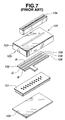
- the printer head generally designated at reference numeral 100 includes a fluorescent luminous tube 101 including a plurality of luminous dots for emitting linear light and acting as a light source. Also, it includes a filter holder 102 for holding red, green and blue color filters R, G and R thereon. The thus-constructed fluorescent luminous tube 101 and filter holder 102 are housed or received in a housing 103. Also, the optical printer head 100 includes a selfoc lens array 104 arranged above the housing 103 for forming incident light into an erected real image at an equi-magnification.
- the housing 103 is formed with an inner space in which the fluorescent luminous tube 101 and filter holder 102 are arranged.
- the housing 103 is mounted thereon with a bottom plate 106 to close an opening 105 of the space while receiving the fluorescent luminous tube 101 and filter holder 102 in the space.
- the housing 103 and bottom plate 106 cooperate with each other to provide a box-like base 107.
- the filter holder 102 is formed thereon with elongated filer holding holes 108 in a manner to extend in a direction perpendicular to a sub-scanning direction indicated at an arrow A in Fig. 8 in which the optical printer head 100 is moved.
- the color filters R, G and B are held in the filter holding holes 108, respectively.
- the fluorescent luminous tube 101 includes a glass plate 101a.
- the filter holder 102 is slid along an upper surface of the glass plate 101a and a wall surface of the opening 105 in the direction A or sub-scanning direction, resulting in selective change-over among red, green and blue colors being carried out.
- the selfoc lens array 104 is formed by constructing a plurality of selfoc lenses into a single module.
- the optical printer head 100 thus constructed, as shown in Fig. 9, causes an end of the upper surface of the glass plate lOla of the fluorescent luminous tube 101 to tend to be caught in the filter holding holes 108 in which the color filters R, G and B are held, when the filter holder 102 is slid in the sub-scanning direction A in Fig. 8 to carry out selective change-over among the color filters R, G and B.
- the filter holder 012 made of a resin material is shaved off to produce shavings or dust.
- the thus-produced dust adheres to a surface of the color filters R, G and B, light emitted from the fluorescent luminous tube 101 is kept from satisfactorily permeating through the filters, to thereby fail to permit light to appropriately form an image on a photosensitive film W, leading to a deterioration in quality of the image.
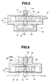
- the optical printer head 110 includes a selfoc lens array 104 arranged in a through-hole 111a formed via a central portion of a body 111.
- the body 111 is provided on a lower portion thereof with a flat section 11b, which cooperates with a frame 112 to constitute a housing 113.
- the selfoc lens array 104 is arranged in a manner to extend through the though-hole 111a into the housing 113.
- the housing 113 has the selfoc lens array 104 and a filter holder 102 received therein while keeping a distal end or outgoing surface 104a of the selfoc lens array 104 and one surface of the filter holder 102 facing each other.
- the housing 113 is formed with an opening 114, on which a bottom plate 106 is mounted, to thereby provide a box-like base 115.
- the bottom plate 106 is so arranged that an inner surface 106a thereof is opposite to the other surface 102b of the filter holder 102.
- the bottom plate 106 is formed with a hole 106b in correspondence to the distal end 104a of the selfoc lens array 104.
- the body 111 is provided at an upper portion thereof with a flange 111c formed therein with a hollow section 111d.
- the hollow section 111d has a flat surface 111e, which is mounted thereon with a fluorescent luminous tube 101 while keeping a glass plate 101a abutted thereagainst.
- the filter holder 102 is slid to select any desired one of color filters R, G and B to drive the fluorescent luminous tube 101.
- the color filter G is selected by way of example.
- Driving of the fluorescent luminous tube 101 permits it to emit light, which is guided through the hollow section 111d, to thereby be collected on an incident surface 104b of the selfoc lens array 104.
- the light thus collected is then discharged through the outgoing surface 104a of the selfoc lens array 104 and partially absorbed by the color filter G.
- Light permeating through the color filter G is guided through the hole 106b of the bottom plate 106 to a photosensitive plate W, to thereby form an image thereon.
- the optical printer head 110 thus constructed causes the outgoing surface 104a of the selfoc lens array 104 to tend to be caught in filter holding holes 108 in which the color filters R, G and B are held, when the filter holder 102 is slid in a sub-scanning direction A to carry out selective change-over among the color filters R, G and B.
- the filter holder 102 When the filter holder 102 is slid in such a state, the filter holder 102 made of a resin material is shaved off to produce shavings or dust.
- the thus-produced dust adheres to a surface of the color filters R, G and B, light emitted from the fluorescent luminous tube 101 is kept from satisfactorily permeating through the filters, to thereby fail to permit light to appropriately form an image on the photosensitive film W, leading to a deterioration in quality of the image as in the optical printer head 100 described above with reference to Figs. 7 to 9.
- the present invention has been made in view of the foregoing disadvantage of the prior art.
- an object of the present invention to provide an optical printer head which is capable of enhancing quality of an image.
- an optical printer head in accordance with the present invention, includes a light source arranged so as to be opposite to a record medium and image formation means provided on a light path defined so as to extend from the light source to the record medium. Light emitted from the light source is collected by the image formation means in synchronism with movement relative to the record medium, to thereby form an image on the record medium.
- the optical printer head also includes filter holding means arranged between the light source and the record medium to hold a plurality of filters thereon and selectively change over any desired one of the filters to position the desired filter on the optical path.
- the filters each are constructed so as to permit light at a predetermined wavelength emitted from the light source to permeate therethrough.
- the optical printer head further includes a base formed with light passages so as to be positioned on the light path and arranged so as to receive only the filter holding means therein while keeping it separated from the light source and image formation means.
- the filter holding means are slidably arranged in the base.
- the light passages each are covered with a light-permeable cover to sealedly close the base.
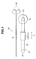
- the optical printer 50 is arranged so as to reciprocate in a sub-scanning direction A with respect to a record medium W such as a color film or the like arranged at a predetermined position by means of transfer means 51.
- the transfer means 51 includes guide means (not shown) for movably guiding the optical printer head 1 (21) in the sub-scanning direction A, a pair of pulleys 53 on which a drive belt 52 is wound while extending therebetween, and a drive motor 54 for rotating one of the pulleys 53.
- the optical printer head 1 (21) is fixed on the drive belt 52 and functions to drive the drive motor 54 to circulate the drive belt 52, resulting in being moved in the sub-scanning direction A while being guided by the guide means.
- the optical printer head 1 is received or housed in a base (not shown) together with the record medium W constituted by a color film.
- a plurality of such color films each acting as the record medium W are held at a predetermined position.
- the color films each are subject to writing by means of light emitted from a fluorescent luminous tube 2 and then outwardly discharged while being interposed between conveyor rollers 55.
- an optical printer head of the illustrated embodiment is generally designated at reference numeral 1 and adapted to be mounted on the optical printer 50.
- the optical printer head 1 includes a fluorescent luminous tube 2 acting as a light source.
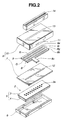
- the fluorescent luminous tube 2 includes an envelope 5 of a substantially rectangular parallelepiped configuration formed by sealedly joining a box-like casing 4 to a light-permeable glass substrate 3 of a rectangular shape.
- the envelope is evacuated at a high vacuum.
- the glass substrate 3 is formed on an inner surface thereof positioned in the envelope 5 with a plurality of anodes each having a phosphor layer deposited thereon, resulting in providing luminous dots 2a which are arranged in two rows in an offset or staggered manner.
- the luminous dots 2a each are formed of a phosphor such as, for example, ZnO:Zn into a square shape.
- the luminous dots 2a in each row are arranged in a manner to be spaced from each other at predetermined intervals in a main scanning direction.
- the fluorescent luminous tube 2 is received in a frame-like container 6 for the fluorescent luminous tube 2.
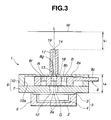
- the luminous tube container 6, as shown in Fig. 3, is fixedly mounted on an upper surface thereof formed with an opening with a filter holder guide 7 using fixing means such as, for example, screws or the like while receiving the fluorescent luminous tube 2 therein.
- the filter holder guide 7 is constituted by a flat substrate or plate.
- the filter holder guide 7 is formed on a central portion thereof with a light passage 12 in the form of a hole.
- the light passage 12 is formed at an outer peripheral edge thereof into a shape like a curved surface.
- the filter holder guide 7 is provided thereon with a filter holder 8 made of a resin material and acting as filter holding means.
- the filter holder 8 is constituted by a flat section 8a and an operation element 8c.
- the flat section 8a is formed thereon with three elongated filter holding holes 8r, 8g and 8b in a manner to extend in a direction of arrangement of the luminous dots 2a or the main scanning direction while being kept parallel to each other.
- the filter holding holes 8r, 8g and 8b have color filters R, G and B held therein, respectively.
- the color filters R, G and B each are constructed so as to permit light at a predetermined wavelength to permeate therethrough.
- the filter holding holes 8r, 8g and 8b each are formed at an outer peripheral edge thereof into configuration like a curved surface.
- the operation element 8c is connected to a drive mechanism (not shown), to thereby slide the filter holder 8 in the sub-scanning direction A.
- the filter holder 8 is received in a base 9, which is constituted by a housing 10 of a box-like shape and the filer holder guide 7 mounted on an opening of the housing 10.
- the housing 10 has a side surface acting to regulate a width of sliding of the filter holder 8.
- the housing 10 is formed on one side surface thereof with a hole 11 through which the operation element 8c of the filter holder 8 is inserted.
- the filter holder 8 is abutted on one side surface thereof against a bottom surface of the housing 10 and the other side surface thereof against the filter holder guide 7.
- the housing 10 is provided at a central portion of the bottom surface thereof with a light passage 13 in the form of a hole in a manner to correspond to the luminous dots 2a of the fluorescent luminous tube 2 and form a pair in cooperation with the light passage 12.
- the light passage 13 is formed at an outer peripheral edge thereof into a shape like a curved surface.
- a selfoc lens array 14 which functions as image forming means for forming light into an image is an optical device formed by integrating a plurality of substantially cylindrical selfoc lenses 16 in correspondence to the luminous dots 2a while rendering central axes thereof parallel to each other.
- the selfoc lens array 14 has a plurality of frame plates 17 fixed on an outer periphery thereof.
- the selfoc lens array 14 is so arranged that one surface 18 thereof or an incident surface thereof faces the light passage 13 of the housing 10, resulting in light emitted from the fluorescent luminous tube 2 being introduced thereto.
- the selfoc leans array 14 also has the other surface or an outgoing surface 19 arranged opposite to the record medium or color film W.
- the selfoc lens array 14 permits light which travels in each of the lenses 16 while meandering at a constant cycle to be emitted from the outgoing surface 19, to thereby form an image on the color film W.
- the selfoc lens array 14 is provided thereon with the color film W in a manner to extend in the sub-scanning direction A.
- a distance L1 between the outgoing surface 19 of the selfoc lens array 14 and a distance L2 between the incident surface 18 of the selfoc lens array 14 and the luminous tube 2 are set to be equal to each other.
- a plane along which light emitted from the luminous dots 2a arranged in the main scanning direction reaches the color film W through the light passages 12 and 13 in a pair and the selfoc lens array 14 will be referred to as a light path L.
- a drive motor 24 is driven to circulate a drive belt 22, so that the optical printer head 1 fixed on the drive belt 22 may be moved in the sub-scanning direction A.
- the filter holder 8 is slid in the sub-scanning direction A perpendicular to the light path L by means of a drive mechanism (not shown) connected to the operation element 8c, resulting in any desired one of the color filters R, G and B being set on the light path L.
- the color filter G is set.
- the filter holder 8 is abutted on one surface thereof against the bottom surface of the housing 10 and abutted on the other surface thereof against the filter holder guide 7, so that the filter holder 8 may be slid in the sub-scanning direction A while being interposed between the bottom surface of the housing 10 and the filter holder guide 7. This prevents the filter holding holes 8r, 8g and 8b of the filter holder 8 from being caught on the fluorescent luminous tube 2, to thereby keep the filter holder 8 from being shaved, unlike the prior art.
- the filter holding holes 8r, 8g and 8b of the filter holder 8 and the light passages 12 and 13 in a pair each are formed at the outer peripheral edge thereof into a curved surface-like shape as described above, to thereby prevent catching between the filter holding holes 8r, 8g and 8b and the light passages 12 and 13, resulting in ensuring smooth movement of the filter holder 8.
- any desired color filter (the color filter G in Fig. 3) is set on the light path L as described above, a drive signal is inputted to the luminous dots 2a of the fluorescent luminous tube 2, leading to luminescence of any desired luminous dots 2a.
- a phosphor for the luminous dots 2a is constituted by ZnO:Zn, which is considerably increased in emission spectrum.
- the printer head 1 permits dot-like light of each of red, green and blue to be irradiated on the color film W by means of the color filters R, G and B and permits an erected real image at an equi-magnification to be formed on the color film W.
- the luminous tube container 6 is released from fixing on the filter holder guide 7 to remove the luminous tube container 6 from the filter holder guide 7, followed by replacement of the luminous tube container with a new one. This permits only the light passage 12 to be exposed to an ambient atmosphere during the replacement, to thereby substantially reduce adhesion of dust to the color filters R, G and B.
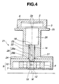
- a second embodiment of an optical printer head according to the present invention is illustrated.
- reference characters like those in Figs. 1 to 3 designate corresponding parts.
- a plane along which light emitted from a fluorescent luminous tube 2 or luminous dots 2a reaches a color film W will be referred to as a light path M.
- An optical printer head of the illustrated embodiment generally designated at reference numeral 21 includes a body 22 for organically coupling the fluorescent luminous tube 2, selfoc lenses 14 and a base 9 to each other.
- the body 22 is formed at a central portion thereof with a lens insertion hole 23 in a manner to be positioned on the light path M.
- the lens insertion hole 23 has a selfoc lens array 14 inserted therein.
- the selfoc lens array 14 has a distal end 27 projected from a flat section 24 of the body 22 provided at a lower portion thereof and inserted into a light passage 28.
- the body 22 is so arranged that the flat section 24 of the body 22 is joined to a bottom surface of a housing 10.
- the body 22 is formed at an upper portion thereof with a flange 25 provided therein with a hollow section 26.
- the flange 25 has a flat surface section, which is mounted thereon with the fluorescent luminous tube 2 while keeping a glass substrate 3 of the fluorescent luminous tube 2 abutted against the flat surface section.
- a base 9 is constituted by the housing 10 of a box-like shape formed with an opening and a filter holder guide 7 made of a resin material and mounted on the opening of the housing 10, as in the first embodiment described above.
- the base 9 has a filter holder 8 housed therein.
- the base 9 is formed with a pair of light passages 12 and 28 in the form of a hole in correspondence to a whole width of the luminous dots 2a of the fluorescent luminous tube 2 in a row direction thereof in a manner to be positioned on the light path M.
- the light passage 12 is formed at a central portion of the filter holder guide 7 so as to extend in a main scanning direction.
- the light passage 28 is formed at a central portion of the bottom surface of the housing 10 in a manner to extend in the row direction of the luminous dots 2a or the main scanning direction.
- the light passage 28, as shown in Fig. 4 includes a diameter-increased hole 28a and a diameter-reduced hole 28b formed integrally with each other in a manner to communicate with each other in a thickness direction of the bottom surface of the housing 10.
- the selfoc lens array 14 is inserted at the distal end 27 thereof into the diameter-increased hole 28a.
- a drive motor 54 is driven to circulate a drive belt 52, so that the optical printer head 21 fixed on the drive belt 22 may be moved in the sub-scanning direction A.
- the filter holder 8 is slid in a direction perpendicular to the light path M by means of a drive mechanism (not shown) connected to an operation element 8c, resulting in any desired one of color filters R, G and B being set on the light path M.
- the filter holder 8 is abutted on one surface thereof against the bottom surface of the housing 10 and abutted on the other surface thereof against the filter holder guide 7, so that the filter holder 8 may be slid in the sub-scanning direction A while being interposed between the bottom surface of the housing 10 and the filter holder guide 7. This prevents filter holding holes 8r, 8g and 8b of the filter holder 8 from being caught on the fluorescent luminous tube 2, to thereby keep the filter holder 8 from being shaved.
- any desired color filter (the color filter G in Fig. 4) is set on the light path M as described above, a drive signal is inputted to the luminous dots 2a of the fluorescent luminous tube 2, leading to luminescence of any desired luminous dots 2a.
- the incident light then travels in each of the selfoc lenses 16 while meandering at a constant cycle and then is emitted from the outgoing surface 19.
- the light is guided through the light passage 28, to thereby be incident on the color filter G set on the light path M, resulting in a part of the light being absorbed by the color filter G.
- the remaining light permeating through the color filter G is guided through the light passage 12, to thereby form an image on the color film W while being maintained as emitted.
- the above-described operation is likewise carried out when the color filter R or B is set on the light path L. Then, the color film W is outwardly discharged while being interposed between carrier rollers 25 after it is subject to writing using light emitted from the fluorescent luminous tube 2.
- a phosphor for the luminous dots 2a is constituted by ZnO:Zn, which is considerably increased in emission spectrum.
- the printer head 1 permits dot-like light of each of red, green and blue to be irradiated on the color film W by means of the color filters R, G and B and an erected real image at an equi-magnification to be formed on the color film W.
- a fluorescent luminous tube is used as the light source 2, however, the light source is not limited to such a fluorescent display device.
- a field emission display device, an organic EL device or the like may be suitably used for this purpose.
- the light path L or M is formed into a straight line.
- a mirror or the like is arranged on the light path L or M while being inclined at a predetermined angle, to thereby refract the light path.
- each are so constructed that the light passages 12 and 13 (diameter-reduced hole 28b) is formed with a light-permeable cover 15 such as glass or the like.
- a light-permeable cover 15 such as glass or the like.
- the filter holding means are arranged separately from the light source and image formation means. This prevents production of dust from the filter holding means due to contact of the filter holding means with the light source and image formation means, to thereby enhance quality of an image formed.
- the base has only the filter holding means housed therein, to thereby prevent the filters from being exposed to an ambient atmosphere, resulting in dust being kept from adhering to the filters, leading to a further improvement in image quality.
- the paired light passages formed on the light path are closed with the light-permeable cover, resulting in the base being sealedly closed. This prevents dust from intruding into the base during replacement of the light source.
Landscapes
- Health & Medical Sciences (AREA)
- General Health & Medical Sciences (AREA)
- Toxicology (AREA)
- Physics & Mathematics (AREA)
- Optics & Photonics (AREA)
- Printers Or Recording Devices Using Electromagnetic And Radiation Means (AREA)
- Projection-Type Copiers In General (AREA)
- Optical Filters (AREA)
- Exposure Or Original Feeding In Electrophotography (AREA)
Applications Claiming Priority (2)
| Application Number | Priority Date | Filing Date | Title |
|---|---|---|---|
| JP25874298A JP3320019B2 (ja) | 1998-09-11 | 1998-09-11 | 光プリントヘッド |
| JP25874298 | 1998-09-11 |
Publications (2)
| Publication Number | Publication Date |
|---|---|
| EP0985540A2 true EP0985540A2 (fr) | 2000-03-15 |
| EP0985540A3 EP0985540A3 (fr) | 2000-11-15 |
Family
ID=17324461
Family Applications (1)
| Application Number | Title | Priority Date | Filing Date |
|---|---|---|---|
| EP99307214A Withdrawn EP0985540A3 (fr) | 1998-09-11 | 1999-09-13 | Tête d'impression optique |
Country Status (3)
| Country | Link |
|---|---|
| US (1) | US6226028B1 (fr) |
| EP (1) | EP0985540A3 (fr) |
| JP (1) | JP3320019B2 (fr) |
Families Citing this family (3)
| Publication number | Priority date | Publication date | Assignee | Title |
|---|---|---|---|---|
| US7375768B2 (en) * | 2004-08-24 | 2008-05-20 | Magix Ag | System and method for automatic creation of device specific high definition material |
| US7713210B2 (en) | 2004-11-23 | 2010-05-11 | St. Jude Medical, Atrial Fibrillation Division, Inc. | Method and apparatus for localizing an ultrasound catheter |
| CN108583035B (zh) * | 2017-12-29 | 2020-11-06 | 浦江县陆恒电子设备有限公司 | 一种便于拆卸压印头的垂直式压印设备 |
Family Cites Families (7)
| Publication number | Priority date | Publication date | Assignee | Title |
|---|---|---|---|---|
| DE2511128C3 (de) * | 1975-03-14 | 1978-03-16 | Karl Heinz Grieger, Farblabor Fuer Berufsfotographie, 7302 Nellingen | Farbmischkopf für fotografische Vergrößerungsgeräte |
| US4763041A (en) * | 1983-10-24 | 1988-08-09 | Ricoh Company, Ltd. | Dot array fluorescent tube for writing optical information in optical printer |
| JP2792874B2 (ja) * | 1988-12-22 | 1998-09-03 | シャープ株式会社 | 液晶カラープリンタ |
| JP3432266B2 (ja) * | 1994-03-18 | 2003-08-04 | シチズン時計株式会社 | カラー画像形成装置 |
| JP3127782B2 (ja) * | 1995-06-22 | 2001-01-29 | 双葉電子工業株式会社 | 光学式プリンタ |
| US5684620A (en) * | 1996-01-30 | 1997-11-04 | Schoonscan, Inc. | High resolution imaging system and method of imaging using the same |
| JPH10166642A (ja) * | 1996-12-06 | 1998-06-23 | Futaba Corp | 光プリンタ及び光プリンタの駆動方法 |
-
1998
- 1998-09-11 JP JP25874298A patent/JP3320019B2/ja not_active Expired - Fee Related
-
1999
- 1999-09-09 US US09/392,652 patent/US6226028B1/en not_active Expired - Fee Related
- 1999-09-13 EP EP99307214A patent/EP0985540A3/fr not_active Withdrawn
Also Published As
| Publication number | Publication date |
|---|---|
| US6226028B1 (en) | 2001-05-01 |
| JP3320019B2 (ja) | 2002-09-03 |
| EP0985540A3 (fr) | 2000-11-15 |
| JP2000085179A (ja) | 2000-03-28 |
Similar Documents
| Publication | Publication Date | Title |
|---|---|---|
| US10330848B2 (en) | Light source module | |
| US20050002096A1 (en) | Screen, image display device and rear projector | |
| US7224494B2 (en) | Image reading apparatus, its light source, and shading correcting apparatus | |
| US20170064125A1 (en) | Illumination apparatus, image sensor unit and image reading apparatus | |
| US6226028B1 (en) | Optical printer head which prevents dust from being generated therein or entering thereinto when in operation or disassembled | |
| US6243125B1 (en) | Optical printer head for an optical printer | |
| EP1190863A1 (fr) | Tête d'impression optique d'appareil d'impression de marge pour imprimer des données sur matière photosensible | |
| JPH09319268A (ja) | 画像記録装置 | |
| US5280364A (en) | Line image sensor and facsimile machine including the same | |
| KR100203673B1 (ko) | 광학식 프린터 및 광학식 프린터의 프린트 헤드 | |
| US6573925B2 (en) | Optical printer module | |
| US6549226B1 (en) | Optical printer head | |
| US6031558A (en) | Image recording apparatus | |
| US20030123110A1 (en) | Optical image scanning device with fluorescent layer as back light | |
| JPH09197232A (ja) | 光学部材の取付機構 | |
| CN1178793C (zh) | 感光纸用荧光打印头 | |
| US20020047891A1 (en) | Exposure head and producing method for a light guiding member thereof | |
| US6323966B1 (en) | Digital scanner | |
| JPS5774173A (en) | Color picture recorder | |
| JPH08278565A (ja) | 画像記録装置 | |
| US6404454B1 (en) | Optical printer and print head thereof | |
| KR100311063B1 (ko) | 광프린터 및 광프린터의 구동방법 | |
| US20020060781A1 (en) | Optical printer | |
| US20040099789A1 (en) | Image sensor module having shortened optical path length and a film scanner using the same | |
| JP4231583B2 (ja) | 光プリントヘッド |
Legal Events
| Date | Code | Title | Description |
|---|---|---|---|
| PUAI | Public reference made under article 153(3) epc to a published international application that has entered the european phase |
Free format text: ORIGINAL CODE: 0009012 |
|
| AK | Designated contracting states |
Kind code of ref document: A2 Designated state(s): DE FR GB |
|
| AX | Request for extension of the european patent |
Free format text: AL;LT;LV;MK;RO;SI |
|
| PUAL | Search report despatched |
Free format text: ORIGINAL CODE: 0009013 |
|
| AK | Designated contracting states |
Kind code of ref document: A3 Designated state(s): AT BE CH CY DE DK ES FI FR GB GR IE IT LI LU MC NL PT SE |
|
| AX | Request for extension of the european patent |
Free format text: AL;LT;LV;MK;RO;SI |
|
| RIC1 | Information provided on ipc code assigned before grant |
Free format text: 7B 41J 2/447 A, 7B 41J 2/525 B, 7B 41J 29/13 B |
|
| 17P | Request for examination filed |
Effective date: 20010212 |
|
| AKX | Designation fees paid |
Free format text: DE FR GB |
|
| STAA | Information on the status of an ep patent application or granted ep patent |
Free format text: STATUS: THE APPLICATION HAS BEEN WITHDRAWN |
|
| 18W | Application withdrawn |
Effective date: 20070425 |