EP0985098B1 - Kreiselpumpe mit einer einlaufleiteinrichtung - Google Patents
Kreiselpumpe mit einer einlaufleiteinrichtung Download PDFInfo
- Publication number
- EP0985098B1 EP0985098B1 EP98925611A EP98925611A EP0985098B1 EP 0985098 B1 EP0985098 B1 EP 0985098B1 EP 98925611 A EP98925611 A EP 98925611A EP 98925611 A EP98925611 A EP 98925611A EP 0985098 B1 EP0985098 B1 EP 0985098B1
- Authority
- EP
- European Patent Office
- Prior art keywords
- impeller
- guide
- vane
- centrifugal pump
- swirl
- Prior art date
- Legal status (The legal status is an assumption and is not a legal conclusion. Google has not performed a legal analysis and makes no representation as to the accuracy of the status listed.)
- Expired - Lifetime
Links
Images
Classifications
-
- F—MECHANICAL ENGINEERING; LIGHTING; HEATING; WEAPONS; BLASTING
- F04—POSITIVE - DISPLACEMENT MACHINES FOR LIQUIDS; PUMPS FOR LIQUIDS OR ELASTIC FLUIDS
- F04D—NON-POSITIVE-DISPLACEMENT PUMPS
- F04D29/00—Details, component parts, or accessories
- F04D29/40—Casings; Connections of working fluid
- F04D29/42—Casings; Connections of working fluid for radial or helico-centrifugal pumps
- F04D29/44—Fluid-guiding means, e.g. diffusers
- F04D29/445—Fluid-guiding means, e.g. diffusers especially adapted for liquid pumps
- F04D29/448—Fluid-guiding means, e.g. diffusers especially adapted for liquid pumps bladed diffusers
-
- F—MECHANICAL ENGINEERING; LIGHTING; HEATING; WEAPONS; BLASTING
- F04—POSITIVE - DISPLACEMENT MACHINES FOR LIQUIDS; PUMPS FOR LIQUIDS OR ELASTIC FLUIDS
- F04D—NON-POSITIVE-DISPLACEMENT PUMPS
- F04D29/00—Details, component parts, or accessories
- F04D29/40—Casings; Connections of working fluid
- F04D29/42—Casings; Connections of working fluid for radial or helico-centrifugal pumps
- F04D29/426—Casings; Connections of working fluid for radial or helico-centrifugal pumps especially adapted for liquid pumps
- F04D29/4273—Casings; Connections of working fluid for radial or helico-centrifugal pumps especially adapted for liquid pumps suction eyes
Definitions
- the invention relates to a centrifugal pump with an axial inlet and one Impeller upstream inlet guide device, which several rigid The guide vanes have one in each on their side facing the impeller or have an edge pointing against the direction of rotation of the impeller.
- Centrifugal pumps with an axial inlet often have an inlet guiding device is connected upstream of the first impeller. Your job is a possible twist to take out of the liquid, so that after the inlet guide there is an axial flow.
- the inlet guide device can consist of several evenly over the circumference of the Distributed guide vanes exist.
- the guide vanes can be in the axis of the inlet are connected to each other and so a star or a cross form.
- Inlet guidance devices are known from DE 471 149 and DE 649 668, whose blades are curved in or against the direction of rotation of the impeller to adapt to special inflow conditions or these bring about.
- the curvature is arched and pulls with each constant axial extension over the entire radial course of the Shovel.
- the curvature is only slight compared to the blade axial extension.
- the angle of attack depends on the type of hydraulics is dependent. It can be determined on the basis of measurements, i. H. he can targeted to achieve different effects on the pump characteristic in all operating points.
- the change achieved by the inlet guide device according to the invention Inflow leads to a performance-saving and the availability increasing operating point adjustment, since the rumor limit clearly to the left is moved. Due to the design of the invention, the Outflow on the impeller improved, so that secondary flows and Detachments behind the impeller blades can be reduced.
- one or several of the guide vanes each on their side facing away from the impeller carry similar guide vanes in shape and size of the swirl vane. It shows that the flow guidance is still by such a guide vane is further improved.
- the invention can be implemented with simple means if - as such known - the guide vanes arranged in the shape of a cross or a star are.
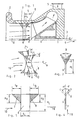
- the centrifugal pump shown in FIG. 1 has a housing 1 with a upstream inlet nozzle 2.
- An impeller 4 is arranged on a shaft 3.
- a pressure connection 5 forms the end in the direction of flow.
- the dimension S which is the distance from the center line of the guide vane 6 from the front edge of the impeller 4 indicates.
- the dimension S which depends on the type of pump, especially the impeller geometry, is dependent - for example with the help of Try - to determine that the inlet guiding device an optimal Influences the flow and thus the pump characteristic.
- the ratio of Guide vanes 6, the guide vanes 7 and the swirl vanes 8 to one another detect.
- a possible angular range between + ⁇ and - ⁇ for is indicated here the direction of the twist scoops 8.
- the positive angle + ⁇ points into the Direction of rotation of the impeller 4.
- a negative angle - ⁇ leaves the guide vane 6 point against the direction of rotation of the impeller 4. Both directions can targeted use of the pump characteristics in the desired sense influence.
- the number of guide vanes 6 depends on the geometry and the specific Characteristic of the pump determined. To determine this is in the range of Knowledge and skills of the relevant pump specialist.
- FIGS. 3 and 4 For better recognition of the possible angular range for the employment of Swirl blade 8 on the guide blade 6, these are even further in FIGS. 3 and 4 shown clearly.
- the blade thickness is also shown in these figures D.
- the guide vane 6 has a height H L
- the guide vane 7 has a height H V
- the height of the swirl vane 8 is indicated by H D.
- L L is the length of the guide vane 6.
- L V indicates the length of the guide vane 7 and L D the length of the swirl vane 8.
- the length and height of the guide vanes 6, the guide vanes 7 and the swirl vanes 8 are designed in such a way that they optimally influence the characteristic curve.
- the swirl vane 8 develops its greatest influence in the area of the wall of the Inlet nozzle 2.
- the Intensity reduced by the inlet guide When recirculation occurs in front of the impeller, the Intensity reduced by the inlet guide.
- the Surface of the inlet guiding device as small as possible and hydraulically smooth should be carried out to reduce the friction loss.
- the blades 6, 7 and 8 of the pre-guide device can also be profiled his.
Landscapes
- Engineering & Computer Science (AREA)
- Mechanical Engineering (AREA)
- General Engineering & Computer Science (AREA)
- Structures Of Non-Positive Displacement Pumps (AREA)
Applications Claiming Priority (3)
| Application Number | Priority Date | Filing Date | Title |
|---|---|---|---|
| DE19722353A DE19722353A1 (de) | 1997-05-28 | 1997-05-28 | Kreiselpumpe mit einer Einlaufleiteinrichtung |
| DE19722353 | 1997-05-28 | ||
| PCT/EP1998/002908 WO1998054471A1 (de) | 1997-05-28 | 1998-05-18 | Kreiselpumpe mit einer einlaufleiteinrichtung |
Publications (2)
| Publication Number | Publication Date |
|---|---|
| EP0985098A1 EP0985098A1 (de) | 2000-03-15 |
| EP0985098B1 true EP0985098B1 (de) | 2003-05-02 |
Family
ID=7830757
Family Applications (1)
| Application Number | Title | Priority Date | Filing Date |
|---|---|---|---|
| EP98925611A Expired - Lifetime EP0985098B1 (de) | 1997-05-28 | 1998-05-18 | Kreiselpumpe mit einer einlaufleiteinrichtung |
Country Status (6)
| Country | Link |
|---|---|
| US (1) | US6273677B1 (ja) |
| EP (1) | EP0985098B1 (ja) |
| JP (1) | JP3802572B2 (ja) |
| DE (2) | DE19722353A1 (ja) |
| ES (1) | ES2196563T3 (ja) |
| WO (1) | WO1998054471A1 (ja) |
Families Citing this family (20)
| Publication number | Priority date | Publication date | Assignee | Title |
|---|---|---|---|---|
| MD2432C2 (ro) * | 2001-09-28 | 2004-11-30 | Сочиетатя Пе Акциунь "Молдовахидромаш" | Evacuator al pompei dinamice |
| MD2246C2 (ro) * | 2001-09-28 | 2004-02-29 | Сочиетатя Пе Акциунь "Молдовахидромаш" | Evacuator cu palete al pompei centrifuge |
| US7089963B2 (en) * | 2002-11-26 | 2006-08-15 | David Meheen | Flow laminarizing device |
| DE102007048019A1 (de) * | 2007-10-06 | 2009-04-09 | Bayerische Motoren Werke Aktiengesellschaft | Pumpe |
| CA2736952C (en) | 2008-09-10 | 2016-11-29 | Pentair Pump Group, Inc. | High-efficiency, multi-stage centrifugal pump and method of assembly |
| PL2172654T5 (pl) * | 2008-10-01 | 2014-04-30 | Grundfos Management As | Agregat z pompą wirową |
| GB0821089D0 (en) * | 2008-11-19 | 2008-12-24 | Ford Global Tech Llc | A method for improving the performance of a radial compressor |
| CN101929465B (zh) * | 2009-06-19 | 2013-12-11 | 德昌电机(深圳)有限公司 | 排水泵 |
| BR112012022324B1 (pt) | 2010-03-05 | 2020-12-22 | Weir Minerals Australia Ltd | dispositivo de admissão de bomba de pasta, membro de desgaste para um dispositivo de admissão de bomba de pasta, conjunto de revestimento de bomba de pasta, método para substituir um membro de desgaste de um dispositivo de admissão de bomba de pasta e aparelho de bomba de pasta |
| US9033685B1 (en) * | 2010-04-26 | 2015-05-19 | Rex N. Await | Well pump flow sleeve installation assembly and method |
| DE102010053510B4 (de) * | 2010-12-04 | 2014-01-23 | Geräte- und Pumpenbau GmbH Dr. Eugen Schmidt | Kühlmittelpumpe |
| DE102011109535B4 (de) * | 2011-08-05 | 2013-08-08 | Sew-Eurodrive Gmbh & Co. Kg | Lüfteranordnung und Motor |
| US9303647B2 (en) | 2011-08-15 | 2016-04-05 | Dale A. Conway | Centrifugal pump anti-air locking system |
| JP6078303B2 (ja) * | 2012-11-13 | 2017-02-08 | 三菱重工業株式会社 | 遠心式流体機械 |
| WO2014116842A1 (en) | 2013-01-23 | 2014-07-31 | Concepts Eti, Inc. | Structures and methods for forcing coupling of flow fields of adjacent bladed elements of turbomachines, and turbomachines incorporating the same |
| CN106574636B (zh) | 2014-06-24 | 2021-08-24 | 概创机械设计有限责任公司 | 用于涡轮机的流动控制结构及其设计方法 |
| DE102014222877A1 (de) * | 2014-11-10 | 2016-05-12 | Siemens Aktiengesellschaft | Laufrad einer Radialturbofluidenergiemaschine, Stufe |
| JP6806551B2 (ja) * | 2016-12-14 | 2021-01-06 | 株式会社豊田中央研究所 | 遠心圧縮機、ターボチャージャ |
| CN110081026B (zh) * | 2019-05-16 | 2020-05-22 | 西安交通大学 | 一种用于减弱离心压缩机叶顶泄漏流的进口导叶及调节方法 |
| EP4193035A1 (en) | 2020-08-07 | 2023-06-14 | Concepts NREC, LLC | Flow control structures for enhanced performance and turbomachines incorporating the same |
Family Cites Families (17)
| Publication number | Priority date | Publication date | Assignee | Title |
|---|---|---|---|---|
| US1716008A (en) * | 1924-09-12 | 1929-06-04 | Westinghouse Electric & Mfg Co | Guide-vane construction for pumps and blowers |
| DE471149C (de) * | 1925-12-24 | 1929-02-12 | Gill Propeller Company Ltd | Hydraulische Maschine mit axialem Durchfluss |
| DE649668C (de) * | 1930-02-04 | 1937-09-04 | James Herbert Wainwright Gill | Laeufer fuer hydraulische Maschinen |
| US2083185A (en) * | 1936-03-23 | 1937-06-08 | American Blower Corp | Fan |
| GB719061A (en) * | 1950-06-21 | 1954-11-24 | United Aircraft Corp | Blade arrangement for improving the performance of a gas turbine plant |
| US2834536A (en) * | 1955-09-29 | 1958-05-13 | Westinghouse Electric Corp | Spin vane controls for fans |
| US4147465A (en) * | 1972-09-02 | 1979-04-03 | Klein, Schanzlin & Becker Aktiengesellschaft | Means for abruptly terminating the flow of fluid in closed fluid circuit systems of nuclear reactor plants or the like |
| JPS5896197A (ja) * | 1981-12-02 | 1983-06-08 | Nissan Motor Co Ltd | 遠心圧縮機の空気取入口 |
| JPS5929799A (ja) * | 1982-08-12 | 1984-02-17 | Matsushita Electric Ind Co Ltd | 送風機 |
| JPS59128998A (ja) * | 1983-01-12 | 1984-07-25 | Matsushita Electric Ind Co Ltd | 電動送風機 |
| FI843263A (fi) * | 1984-08-17 | 1986-02-18 | Nokia Oy Ab | Centrifugalflaekt samt instaellningsvinggrupp och instaellningsvingserie foer dylika flaektar. |
| US4884942A (en) * | 1986-06-30 | 1989-12-05 | Atlas Copco Aktiebolag | Thrust monitoring and balancing apparatus |
| US4764088A (en) * | 1987-04-21 | 1988-08-16 | Kapich Davorin D | Inlet guide vane assembly |
| US4854818A (en) * | 1987-12-28 | 1989-08-08 | Rockwell International Corporation | Shrouded inducer pump |
| JPH07117076B2 (ja) * | 1989-05-26 | 1995-12-18 | 太平洋機工株式会社 | ウオータジェット推進機のためのターボ型ポンプ用羽根車およびこの羽根車を有するターボ型ポンプ |
| DE4321260C1 (de) * | 1993-06-25 | 1995-03-09 | Westphal Dieter Dipl Ing Dipl | Blutpumpe als Zentrifugalpumpe |
| US6375419B1 (en) * | 1995-06-02 | 2002-04-23 | United Technologies Corporation | Flow directing element for a turbine engine |
-
1997
- 1997-05-28 DE DE19722353A patent/DE19722353A1/de not_active Withdrawn
-
1998
- 1998-05-18 JP JP50017399A patent/JP3802572B2/ja not_active Expired - Fee Related
- 1998-05-18 WO PCT/EP1998/002908 patent/WO1998054471A1/de active IP Right Grant
- 1998-05-18 EP EP98925611A patent/EP0985098B1/de not_active Expired - Lifetime
- 1998-05-18 DE DE59808172T patent/DE59808172D1/de not_active Expired - Fee Related
- 1998-05-18 US US09/424,786 patent/US6273677B1/en not_active Expired - Fee Related
- 1998-05-18 ES ES98925611T patent/ES2196563T3/es not_active Expired - Lifetime
Also Published As
| Publication number | Publication date |
|---|---|
| JP3802572B2 (ja) | 2006-07-26 |
| US6273677B1 (en) | 2001-08-14 |
| WO1998054471A1 (de) | 1998-12-03 |
| DE19722353A1 (de) | 1998-12-03 |
| JP2001526757A (ja) | 2001-12-18 |
| EP0985098A1 (de) | 2000-03-15 |
| ES2196563T3 (es) | 2003-12-16 |
| DE59808172D1 (de) | 2003-06-05 |
Similar Documents
| Publication | Publication Date | Title |
|---|---|---|
| EP0985098B1 (de) | Kreiselpumpe mit einer einlaufleiteinrichtung | |
| DE69620635T2 (de) | Pumpenlaufrad mit getrennten, versetzten leitschaufeln | |
| DE69915283T2 (de) | Kreiselrad für turbomaschinen | |
| EP2096316B1 (de) | Gehäusestrukturierung für Axialverdichter im Nabenbereich | |
| EP2699803B1 (de) | Laufrad für kreiselpumpen | |
| EP2275643B1 (de) | Triebwerkschaufel mit überhöhter Vorderkantenbelastung | |
| DE102007056953B4 (de) | Strömungsarbeitsmaschine mit Ringkanalwandausnehmung | |
| EP1798375A2 (de) | Schaufelprofil für verstellbare Statorschaufeln | |
| EP0043452A2 (de) | Vorrichtung zur Regelung von Axialverdichtern | |
| DE102005042115A1 (de) | Schaufel einer Strömungsarbeitsmaschine mit blockweise definierter Profilskelettlinie | |
| DE2421237C2 (de) | Eintauchpumpe | |
| EP2932105B1 (de) | Pumpvorrichtung mit einem strömungsleitelement | |
| AT405756B (de) | Leitschaufel für kaplanturbinen | |
| WO1995025895A1 (de) | Einrichtung zur geräuschreduzierung bei kreiselpumpen | |
| DE2360570A1 (de) | Kreiselpumpe | |
| CH317623A (de) | Schaufelung für mit Fliehkraft wirkende Fördermaschinen | |
| EP0944770B1 (de) | Wasserturbine oder -pumpe | |
| DE2037785A1 (de) | Rotationspumpe mit zusätzlichem Speiselaufrad | |
| EP1556616B1 (de) | Laufrad für eine kreiselpumpe | |
| CH650563A5 (en) | Diffuser in a centrifugal driven machine | |
| WO2004031573A1 (de) | Laufrad einer hydraulischen maschine | |
| DE4220960A1 (de) | Schaufeln für Arbeitsmaschinen | |
| DE4328396A1 (de) | Einschaufelrad für Kreiselpumpen | |
| DE323190C (de) | Laufschaufel fuer Schnellaeuferwasserturbinen mit sichelausschnittfoermigem Meridianschnitt | |
| DE3038735T1 (de) | Vane pump |
Legal Events
| Date | Code | Title | Description |
|---|---|---|---|
| PUAI | Public reference made under article 153(3) epc to a published international application that has entered the european phase |
Free format text: ORIGINAL CODE: 0009012 |
|
| 17P | Request for examination filed |
Effective date: 19990901 |
|
| AK | Designated contracting states |
Kind code of ref document: A1 Designated state(s): BE DE ES FR GB IT NL |
|
| 17Q | First examination report despatched |
Effective date: 20020731 |
|
| GRAH | Despatch of communication of intention to grant a patent |
Free format text: ORIGINAL CODE: EPIDOS IGRA |
|
| GRAH | Despatch of communication of intention to grant a patent |
Free format text: ORIGINAL CODE: EPIDOS IGRA |
|
| GRAA | (expected) grant |
Free format text: ORIGINAL CODE: 0009210 |
|
| AK | Designated contracting states |
Designated state(s): BE DE ES FR GB IT NL |
|
| PG25 | Lapsed in a contracting state [announced via postgrant information from national office to epo] |
Ref country code: FR Free format text: LAPSE BECAUSE OF NON-PAYMENT OF DUE FEES Effective date: 20030502 |
|
| REG | Reference to a national code |
Ref country code: GB Ref legal event code: FG4D Free format text: NOT ENGLISH |
|
| PG25 | Lapsed in a contracting state [announced via postgrant information from national office to epo] |
Ref country code: BE Free format text: LAPSE BECAUSE OF NON-PAYMENT OF DUE FEES Effective date: 20030531 |
|
| REF | Corresponds to: |
Ref document number: 59808172 Country of ref document: DE Date of ref document: 20030605 Kind code of ref document: P |
|
| GBT | Gb: translation of ep patent filed (gb section 77(6)(a)/1977) | ||
| BERE | Be: lapsed |
Owner name: *KSB A.G. Effective date: 20030531 |
|
| REG | Reference to a national code |
Ref country code: ES Ref legal event code: FG2A Ref document number: 2196563 Country of ref document: ES Kind code of ref document: T3 |
|
| PLBE | No opposition filed within time limit |
Free format text: ORIGINAL CODE: 0009261 |
|
| STAA | Information on the status of an ep patent application or granted ep patent |
Free format text: STATUS: NO OPPOSITION FILED WITHIN TIME LIMIT |
|
| 26N | No opposition filed |
Effective date: 20040203 |
|
| EN | Fr: translation not filed | ||
| PGFP | Annual fee paid to national office [announced via postgrant information from national office to epo] |
Ref country code: NL Payment date: 20090527 Year of fee payment: 12 Ref country code: ES Payment date: 20090514 Year of fee payment: 12 |
|
| PGFP | Annual fee paid to national office [announced via postgrant information from national office to epo] |
Ref country code: IT Payment date: 20090522 Year of fee payment: 12 Ref country code: DE Payment date: 20090519 Year of fee payment: 12 |
|
| PGFP | Annual fee paid to national office [announced via postgrant information from national office to epo] |
Ref country code: GB Payment date: 20090521 Year of fee payment: 12 |
|
| REG | Reference to a national code |
Ref country code: NL Ref legal event code: V1 Effective date: 20101201 |
|
| GBPC | Gb: european patent ceased through non-payment of renewal fee |
Effective date: 20100518 |
|
| PG25 | Lapsed in a contracting state [announced via postgrant information from national office to epo] |
Ref country code: IT Free format text: LAPSE BECAUSE OF NON-PAYMENT OF DUE FEES Effective date: 20100518 Ref country code: NL Free format text: LAPSE BECAUSE OF NON-PAYMENT OF DUE FEES Effective date: 20101201 |
|
| PG25 | Lapsed in a contracting state [announced via postgrant information from national office to epo] |
Ref country code: DE Free format text: LAPSE BECAUSE OF NON-PAYMENT OF DUE FEES Effective date: 20101201 |
|
| REG | Reference to a national code |
Ref country code: ES Ref legal event code: FD2A Effective date: 20110715 |
|
| PG25 | Lapsed in a contracting state [announced via postgrant information from national office to epo] |
Ref country code: ES Free format text: LAPSE BECAUSE OF NON-PAYMENT OF DUE FEES Effective date: 20110705 Ref country code: GB Free format text: LAPSE BECAUSE OF NON-PAYMENT OF DUE FEES Effective date: 20100518 |
|
| PG25 | Lapsed in a contracting state [announced via postgrant information from national office to epo] |
Ref country code: ES Free format text: LAPSE BECAUSE OF NON-PAYMENT OF DUE FEES Effective date: 20100519 |