EP2275643B1 - Triebwerkschaufel mit überhöhter Vorderkantenbelastung - Google Patents
Triebwerkschaufel mit überhöhter Vorderkantenbelastung Download PDFInfo
- Publication number
- EP2275643B1 EP2275643B1 EP10005471.7A EP10005471A EP2275643B1 EP 2275643 B1 EP2275643 B1 EP 2275643B1 EP 10005471 A EP10005471 A EP 10005471A EP 2275643 B1 EP2275643 B1 EP 2275643B1
- Authority
- EP
- European Patent Office
- Prior art keywords
- skeleton line
- camber
- fluid
- distribution
- blade
- Prior art date
- Legal status (The legal status is an assumption and is not a legal conclusion. Google has not performed a legal analysis and makes no representation as to the accuracy of the status listed.)
- Not-in-force
Links
- 238000009826 distribution Methods 0.000 claims description 44
- 238000013459 approach Methods 0.000 claims description 3
- 230000000630 rising effect Effects 0.000 claims description 2
- 238000005452 bending Methods 0.000 claims 1
- 239000012530 fluid Substances 0.000 description 12
- 230000002349 favourable effect Effects 0.000 description 9
- 230000003247 decreasing effect Effects 0.000 description 6
- 230000009467 reduction Effects 0.000 description 2
- 230000001419 dependent effect Effects 0.000 description 1
- 238000009792 diffusion process Methods 0.000 description 1
- 230000000694 effects Effects 0.000 description 1
- 239000007788 liquid Substances 0.000 description 1
- 238000000926 separation method Methods 0.000 description 1
Images


Classifications
-
- F—MECHANICAL ENGINEERING; LIGHTING; HEATING; WEAPONS; BLASTING
- F01—MACHINES OR ENGINES IN GENERAL; ENGINE PLANTS IN GENERAL; STEAM ENGINES
- F01D—NON-POSITIVE DISPLACEMENT MACHINES OR ENGINES, e.g. STEAM TURBINES
- F01D5/00—Blades; Blade-carrying members; Heating, heat-insulating, cooling or antivibration means on the blades or the members
- F01D5/12—Blades
- F01D5/14—Form or construction
- F01D5/141—Shape, i.e. outer, aerodynamic form
-
- F—MECHANICAL ENGINEERING; LIGHTING; HEATING; WEAPONS; BLASTING
- F01—MACHINES OR ENGINES IN GENERAL; ENGINE PLANTS IN GENERAL; STEAM ENGINES
- F01D—NON-POSITIVE DISPLACEMENT MACHINES OR ENGINES, e.g. STEAM TURBINES
- F01D5/00—Blades; Blade-carrying members; Heating, heat-insulating, cooling or antivibration means on the blades or the members
- F01D5/12—Blades
- F01D5/14—Form or construction
- F01D5/20—Specially-shaped blade tips to seal space between tips and stator
-
- F—MECHANICAL ENGINEERING; LIGHTING; HEATING; WEAPONS; BLASTING
- F05—INDEXING SCHEMES RELATING TO ENGINES OR PUMPS IN VARIOUS SUBCLASSES OF CLASSES F01-F04
- F05D—INDEXING SCHEME FOR ASPECTS RELATING TO NON-POSITIVE-DISPLACEMENT MACHINES OR ENGINES, GAS-TURBINES OR JET-PROPULSION PLANTS
- F05D2240/00—Components
- F05D2240/20—Rotors
- F05D2240/30—Characteristics of rotor blades, i.e. of any element transforming dynamic fluid energy to or from rotational energy and being attached to a rotor
- F05D2240/303—Characteristics of rotor blades, i.e. of any element transforming dynamic fluid energy to or from rotational energy and being attached to a rotor related to the leading edge of a rotor blade
Definitions
- the invention relates to a fluid power machine comprising an engine blade with excessive leading edge load.
- the invention relates to a fluid flow machine with a blade according to the preamble of claim 1.
- the blading in question is provided within a main flow path, bounded on the outside by a housing and internally bounded by a hub.
- a rotor comprises a plurality of rotor blades attached to a rotating shaft and emits energy to the working fluid
- a stator consists of a plurality of fixed, mostly in the housing mounted stator blades.
- the fluid flow machine comprises a rotor with a fixed connection to a rotating hub and a free blade end with a gap on the housing.
- the fluid flow machine alternatively comprises a stator which has a fixed connection to the edge on the housing side and has a free blade end with a gap to the hub on the hub side.
- the present invention relates to fluid flow machines such as fans, compressors, pumps and fans in axial, semi-axial or also radial design.
- the working medium (fluid) can be gaseous or liquid.
- the following is known from the prior art:
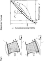
- the Fig. 1 1 shows, on the left side, a schematic representation of two blade configurations according to the prior art in the meridian plane formed by the radial direction r and the axial direction x. It is a rotor blade row 4 with a gap on the housing 1 (top), wherein the housing 1 is or in special cases also rotates and the blade row rotates about the machine axis 3.
- stator blades 5 It is also a row of stator blades 5 with a gap on the hub 2 (bottom), wherein the hub 2 rotates about the machine axis 3 or, in special cases, also rests and the row of blades 5 stands.
- the blade profile cut directly on the running gap of a rotor 4 or stator 5 is designed such that the profile load and thus the profile curvature in the region of the leading edge does not exceed a certain level, because conventional design rules based on considerations of the nature of two-dimensional flows around profiles recommend this.
- the right side of the Fig. 1 shows different, the prior art corresponding distributions of the skeleton line curvature in the profile section directly on the running gap, shown as a relative curvature ⁇ * over the related run length s * (for definitions see Fig. 3 ).
- This category includes the so-called CDA (controlled diffusion aerofoils) US 4431376 A , From an aerodynamic point of view, the CDA aims for a moderate profile frontload.
- CDA controlled diffusion aerofoils
- the present invention has for its object to provide a fluid flow machine of the type mentioned, which while avoiding the disadvantages of In the prior art, a very effective influencing of the edge flow is achieved by an excessive skeleton curve curvature in the region of the front edge of the blade profile cuts located near the running gap.
- a fluid power machine comprising a blade disposed in a main flow path bounded by a hub and a housing, wherein a gap is provided between an end of the blade and the main flow path boundary, hub or housing, and thus a free blade end is formed, wherein in at least one blade profile streamline section in the area between the gap and one
- the Fig.2 gives a precise definition of the meridional flow lines and the streamline profile sections.
- the mean meridional flow line 7 is formed by the geometric center of an annular channel 6. If one establishes a normal at each location of the middle streamline 7, one obtains the course of the ring channel width W along the flow path and, on the other hand, a number of normals with whose help further meridional flow lines result with the same relative subdivision in the direction of the channel height.
- the intersection of a meridional streamline with a blade results in a streamline profile intersection.
- the respective skeleton line type for a streamline profile intersection is defined in relative representation by means of the relative curvature ⁇ * and the related run length s *, see Figure 3 , The figure shows a streamline profile section of the blade on a meridian flow surface (um plane).
- the inclination angle ⁇ p and the run length s P covered up to this point are determined in all points of the skeleton line.
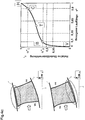
- the Fig. 4a shows a family of inventive crevices near the profile skeleton curves. They are characterized in that the relative skeleton curve curvature ⁇ * always has values greater than or equal to 0.35 for related run lengths of s *> 0.1.
- Fig. 4a The distribution shown shows the special case according to the invention of a change of the skeleton curve curvature sign.
- the skeleton line is convexly curved towards the profile suction side in a part of the run length s * and concave in a lower part of the run length s *, as is the case if values of ⁇ *> 1 at least in part of the run length s * are provided.
- the excessive leakage of the profile leading edge region in the vicinity of the running gap influences the leakage flows occurring at the running gap.
- values of the relative skeleton curve curvature ⁇ * of greater than or equal to 0.35 or even greater than 0.5 or in special cases greater than or equal to 0.65 or in extreme cases greater than 1.0 already at a relative run length of s * 0.1.
- a curvature distribution ⁇ * f (s *), the high gradient at the starting point A, starting in the further course of the point B approaches with decreasing gradient.
- the Fig. 4b shows an also according to the invention Schar of Skelettlinienwölbungsveranderen, which is also suitable for aerodynamically highly loaded profiles.
- the curvature at point T changes its sign.
- an S-shaped skeleton line curvature distribution results according to the invention, corresponding to FIG Fig. 4b shown crowd.
- the value ⁇ * C provided at s * 0.9 and thus the position of the point C is restricted.
- particularly favorable solutions result if ⁇ * C ⁇ * B + 0.75 (1- ⁇ * B ).
- the skeleton line curvature distribution according to the invention is to be provided in at least one vane stream section in the region between the gap and a vane section at 5% of the main flow path width (0.05 W).
- This skeleton line curvature distribution can be provided directly at the gap, but according to the invention must be provided at least within the 5% of the main flow path width W adjacent to the gap.
- Pumps and fans have an edge flow control which, while maintaining the same stability, can increase the efficiency of each stage by approximately 0.3%.
- a reduction in the number of blades of up to 20% is possible.
- the inventive concept is applicable to different types of turbomachines and, depending on the degree of utilization of the concept, leads to reductions in costs and weight for the turbomachine of 2% to 10%.
Landscapes
- Engineering & Computer Science (AREA)
- Mechanical Engineering (AREA)
- General Engineering & Computer Science (AREA)
- Physics & Mathematics (AREA)
- Fluid Mechanics (AREA)
- Structures Of Non-Positive Displacement Pumps (AREA)
Description
- Die Erfindung bezieht sich auf eine Strömungsarbeitsmaschine umfassend eine Triebwerksschaufel mit überhöhter Vorderkantenbelastung.
- Die aerodynamische Belastbarkeit und die Effizienz von Strömungsarbeitsmaschinen, beispielsweise Bläsern, Verdichtern, Pumpen und Ventilatoren, wird insbesondere durch das Wachstum und die Ablösung von Grenzschichten im Bereich von Rotor- und Statorradialspalten und von festen Schaufelenden nahe der Ringkanalwände begrenzt. Der Stand der Technik hält für dieses fundamentale Problem nur bedingt Lösungen bereit. Der allgemeine Gedanke der Randbeeinflussung durch Änderung des Skelettlinientyps entlang der Schaufelhöhe ist im Stand der Technik enthalten, doch sind die bekannten Lösungen, insbesondere für die Strömungsverhältnisse an einem Schaufelende mit Radialspalt, nicht genügend zielgerichtet.
- Im Einzelnen betrifft die Erfindung eine Strömungsarbeitsmaschine mit einer Schaufel gemäß dem einleitenden Teil des Anspruchs 1. Die betreffende Beschaufelung ist innerhalb eines Hauptströmungspfades vorgesehen, außen begrenzt durch ein Gehäuse und innen begrenzt durch eine Nabe. Während ein Rotor mehrere an einer rotierenden Welle befestigte Rotorschaufeln umfasst und Energie an das Arbeitsmedium abgibt, besteht ein Stator aus mehreren feststehenden, meist im Gehäuse befestigten Statorschaufeln.
- Zum einen umfasst die Strömungsarbeitsmaschine einen Rotor mit fester Anbindung an einer rotierenden Nabe und einem freien Schaufelende mit Spalt am Gehäuse. In analoger Weise umfasst die Strömungsarbeitsmaschine alternativ einen Stator, der gehäuseseitig eine feste Verbindung zum Rand aufweist und nabenseitig ein freies Schaufelende mit Spalt zur Nabe besitzt.
- Die vorliegende Erfindung bezieht sich auf Strömungsarbeitsmaschinen wie etwa Bläser, Verdichter, Pumpen und Ventilatoren in axialer, halbaxialer oder auch radialer Bauart. Das Arbeitsmedium (Fluid) kann gasförmig oder flüssig sein. Aus dem Stand der Technik ist folgendes bekannt:
DieFig. 1 zeigt auf der linken Seite in schematischer Darstellung zwei Schaufelkonfigurationen nach dem Stand der Technik in der durch die Radialrichtung r und die Axialrichtung x gebildeten Meridianebene. Es handelt sich dabei um eine Rotorschaufelreihe 4 mit Spalt am Gehäuse 1 (oben), wobei das Gehäuse 1 steht oder in Spezialfällen auch rotiert und die Schaufelreihe um die Maschinenachse 3 rotiert. Es handelt sich weiterhin um eine Statorschaufelreihe 5 mit Spalt an der Nabe 2 (unten), wobei die Nabe 2 um die Maschinenachse 3 rotiert oder in Spezialfällen auch ruht und die Schaufelreihe 5 steht. Gemäß dem Stand der Technik ist der Schaufelprofilschnitt direkt am Laufspalt eines Rotors 4 oder Stators 5 so gestaltet, dass die Profilbelastung und somit die Profilwölbung im Bereich der Vorderkante ein bestimmtes Maß nicht übersteigt, weil konventionelle Entwurfsregeln, basierend auf Überlegungen zur Natur zweidimensionaler Strömungen um Profile dies empfehlen. - Die rechte Seite der
Fig. 1 zeigt unterschiedliche, dem Stand der Technik entsprechende Verteilungen der Skelettlinienwölbung im Profilschnitt direkt am Laufspalt, dargestellt als relative Wölbung α* über der bezogenen Lauflänge s* (Definitionen sieheFig. 3 ). Kennzeichnend für alle Wölbungsverteilungen ist, dass bei einer bezogenen Lauflänge von s*=0,1 bei Weitem nicht Werte der relativen Wölbung von α*>=0,35 oder gar α*>=0,50 oder α*>=0,65 vorgesehen werden. Dadurch wird eine extreme Vorderkantenbelastung bewusst vermieden. In diese Kategorie fallen die sogenannten CDA (controlled diffusion aerofoils) gemäßUS 4431376 A . Aerodynamisch betrachtet wird durch die CDA eine moderate Profilvorderlast angestrebt. - Als nachteilig erweist sich beim Stand der Technik, dass die entsprechenden Schaufelformen oft bewusst mit geringer Komplexität bezüglich der Skelettlinienform entworfen werden. Für den Fall starker Laufspaltleckageströmungen fehlt eine überhöhte Profilwölbung im Vorderkantenbereich der Schaufelprofilschnitte in der Nähe des Laufspaltes, um eine im Schaufelmittenbereich günstige übliche Skelettlinienwölbungsverteilung auf angemessene Weise mit einer für die Randbereiche günstigeren Skelettlinienwölbungsverteilung zu kombinieren.
- Ferner ist aus der
DE 10 2005 042 115 A1 eine Strömungsarbeitsmaschine gemäß dem Oberbegriff des Anspruchs 1 bekannt. - Der vorliegenden Erfindung liegt die Aufgabe zugrunde, eine Strömungsarbeitsmaschine der eingangs genannten Art zu schaffen, welche unter Vermeidung der Nachteile des Standes der Technik eine sehr wirkungsvolle Beeinflussung der Randströmung durch eine überhöhte Skelettlinienwölbung im Bereich der Vorderkante der nahe des Laufspaltes befindlichen Schaufelprofilschnitte erreicht.
- Erfindungsgemäß wird die Aufgabe durch die Merkmalskombination des Anspruchs 1 gelöst, die Unteransprüche zeigen weitere vorteilhafte Ausgestaltungen der Erfindung.
- Erfindungsgemäß ist somit eine Schaufel einer Strömungsarbeitsmaschine, welche mindestens innerhalb der an den Spalt angrenzenden 5% der Hauptströmungspfadweite eine Skelettlinienwölbungsverteilung vorgesehen, die bei einer bezogenen Lauflänge von s*=0,1 einen überhöhten Wert der relativen Skelettlinienwölbung von mindestens α*=0,35 aufweist.
- Wie sich insbesondere aus der
Fig. 4c (siehe nachfolgende Beschreibung) ergibt, ist am vorderen Bereich der Schaufel ein sehr hoher Anstieg der Strömungs-Umlenkung vorgesehen. - Die Erfindung lässt sich auch wie folgt darstellen:
Strömungsarbeitsmaschine umfassend eine Schaufel, welche in einem von einer Nabe und einem Gehäuse berandeten Hauptströmungspfad angeordnet ist, wobei zwischen einem Ende der Schaufel und der Hauptströmungspfadberandung, Nabe oder Gehäuse, ein Spalt vorgesehen ist und somit ein freies Schaufelende ausgebildet ist, wobei in mindestens einem Schaufelprofilstromlinienschnitt im Bereich zwischen dem Spalt und einem - Schaufelschnitt im Abstand von 30% der Hauptströmungspfadweite W vom Spalt eine Skelettlinienwölbungsverteilung vorgesehen ist, die bei einer bezogenen Lauflänge von s*=0,1 einen überhöhten Wert der relativen Skelettlinienwölbung von mindestens α*=0,35 aufweist, wobei s* die auf die Gesamtlauflänge der Profilskelettlinie bezogene lokale Lauflänge darstellt und α* als die von der Vorderkante bis zu einer bezogenen Lauflänge s* erreichte Winkeländerung der Skelettlinie bezogen auf die Gesamtwölbung der Skelettlinie gebildet wird, wobei die Skelettlinienwölbungsverteilung in dieser Darstellung im Vorderkantenpunkt V (s*=0,α*=0) beginnt und im Hinterkantenpunkt H (s*=1,α*=1) endet, wobei insbesondere mindestens direkt am Spalt eine Skelettlinienwölbungsverteilung vorgesehen ist, die bei einer bezogenen Lauflänge von s*=0,1 einen überhöhten Wert der relativen Skelettlinienwölbung von mindestens α*=0,35 aufweist,
und mindestens innerhalb der an den Spalt angrenzenden 5% der Hauptströmungspfadweite eine Skelettlinienwölbungsverteilung vorgesehen ist, die bei einer bezogenen Lauflänge von s*=0,1 einen überhöhten Wert der relativen Skelettlinienwölbung von mindestens α*=0,35 aufweist,
wobei bevorzugt bei einer bezogenen Lauflänge von s*=0,1 ein überhöhter Wert der relativen Skelettlinienwölbung von mindestens α*=0,50 vorgesehen ist,
wobei bevorzugt die Skelettlinienwölbungsverteilung die mit hohem Gradienten im Vorderkantenpunkt V beginnt und im weiteren Verlauf sich der bezogenen Lauflänge s*=0,1 mit abnehmendem Gradienten nähert,
wobei bevorzugt die Skelettlinienwölbungsverteilung sich von der bezogenen Lauflänge s*=0,1 aus in Richtung des Hinterkantenpunktes H gehend knickfrei und mit abnehmendem oder konstanten Gradienten bis zum Hinterkantenpunkt H fortsetzt, wobei die Stelle stärkster Krümmung der Skelettlinienwölbungsverteilung im Bereich 0 <= s* <= 0,2 vorgesehen ist,
wobei vorteilhaft die Skelettlinienwölbungsverteilung sich von der bezogenen Lauflänge s*=0,1 aus in Richtung des Hinterkantenpunktes H gehend knickfrei zunächst mit weiter geringer werdenden Gradienten fortsetzt und ab einem Punkt T, in dem die Krümmung ihr Vorzeichen wechselt, für wenigstens einen Teil des Bereiches 0,1 <= s* <= 1 wieder ansteigende Gradienten aufweist,
wobei weiter bevorzugt die Skelettlinienwölbungsverteilung nur einen einzigen Krümmungsvorzeichenwechsel besitzt und somit einen S-förmigen Verlauf zeigt,
und/oder dass der Punkt T des ersten Krümmungsvorzeichenwechsels im Bereich 0,35 <= s* <= 0,65 vorgesehen ist,
wobei bevorzugt weiterhin die Skelettlinienwölbungsverteilung wenigstens in einem Teil des Bereiches 0,1 <= s* <= 1 bei konstanten Werten der relativen Skelettlinienwölbung α* verläuft,
und/oder die Skelettlinienwölbungsverteilung bei einer bezogenen Lauflänge von s*=0,9 einen Wert der relativen Skelettlinienwölbung von α* < α*(s*=0,1) + 0,75 (1 - α*(s*=0,1)) aufweist,
und/oder die Skelettlinienwölbungsverteilung gekrümmt, abschnittsweise gekrümmt oder abschnittsweise geradlinig verläuft und auf diese Weise zwischen dem Vorderkantenpunkt V und dem Hinterkantenpunkt H eine beliebige Anzahl von Knickstellen aufweist,
wobei weiter bevorzugt bei einer bezogenen Lauflänge von s* = 0,1 ein überhöhter Wert der relativen Skelettlinienwölbung von mindestens α* = 0,65 vorgesehen ist,
wobei weiter bevorzugt bei einer bezogenen Lauflänge von s* = 0,1 ein überhöhter Wert der relativen Skelettlinienwölbung von mindestens α* = 1,0 vorgesehen ist,
und/oder in wenigstens einem Teil der Lauflänge von 0,1 < s* < 1 Werte der relativen Skelettlinienwölbung von α* > 1 vorgesehen sind. - Im Folgenden wird die Erfindung anhand von Ausführungsbeispielen in Verbindung mit den Figuren beschrieben. Dabei zeigt:
- Fig.1:
- eine schematische Darstellung zum Stand der Technik,
- Fig.2:
- die Definition von Meridianstromlinien und Stromlinienprofilschnitten,
- Fig.3:
- die Definition der Skelettlinie eines Stromlinienprofilschnitts,
- Fig.4a:
- erfindungsgemäße Lösungen,
- Fig.4b:
- weitere erfindungsgemäße Lösungen,
- Fig.4c:
- weitere erfindungsgemäße Lösungen.
- Die
Fig.2 gibt eine genaue Definition der Meridianstromlinien und der Stromlinienprofilschnitte an. Die mittlere Meridianstromlinie 7 wird durch die geometrische Mitte eines Ringkanals 6 gebildet. Errichtet man an jedem Ort der mittleren Stromlinie 7 eine Normale, so erhält man zum einen den Verlauf der Ringkanalweite W entlang des Strömungspfades und zum anderen eine Anzahl von Normalen, mit deren Hilfe sich bei gleicher relativer Unterteilung in Richtung der Kanalhöhe weitere Meridianstromlinien ergeben. Der Schnitt einer Meridianstromlinie mit einer Schaufel ergibt einen Stromlinienprofilschnitt. - Der jeweilige Skelettlinientyp für einen Stromlinienprofilschnitt wird in relativer Darstellung mit Hilfe der relativen Wölbung α* und der bezogenen Lauflänge s* festgelegt, siehe
Fig.3 . Die Figur zeigt einen Stromlinienprofilschnitt der Schaufel auf einer Meridianstromfläche (u-m-Ebene). - Dazu werden in allen Punkten der Skelettlinie der Neigungswinkel αp und die bis dorthin zurückgelegte Lauflänge sP bestimmt. Als Bezugsgrößen werden die Neigungswinkel an Vorder- und Hinterkante α1 und α2 sowie die Gesamtlauflänge der Skelettlinie S verwendet. Es gilt:

- Die
Fig. 4a zeigt eine Schar erfindungsgemäßer spaltnaher Verteilungen der Profilskelettlinienwölbung. Sie sind dadurch gekennzeichnet, dass die relative Skelettlinienwölbung α* bei bezogenen Lauflängen von s*>0,1 stets Werte größer oder gleich 0,35 aufweist. - Erfindungsgemäß ist es weiter vorteilhaft, wenn die relative Skelettlinienwölbung α* bei bezogenen Lauflängen von s*>0,1 stets Werte gleich oder größer 0,50 aufweist. In besonderen Fällen kann es erfindungsgemäß sogar günstig sein, wenn die relative Skelettlinienwölbung α* ab einer bezogenen Lauflänge von s*=0,1 den Wert 0,65 oder gar 1,0 annimmt.
- Die oberste in
Fig. 4a dargestellte Verteilung zeigt den erfindungsgemäßen Spezialfall eines Wechsels des Skelettlinienkrümmungsvorzeichens. In diesem dargestellten Fall ist die Skelettlinie zur Profilsaugseite hin in einem Teil der Lauflänge s* konvex und in einem unteren Teil der Lauflänge s* konkav gekrümmt, wie es sich ergibt, wenn wenigstens in einem Teil der Lauflänge s* Werte von α* > 1 vorgesehen sind. - Der bei s*=0,1 vorliegende Wert von α* wird im weiteren mit α*B bezeichnet, d. h. α*B = α*(s*=0,1). In analoger Weise wird der bei s*=0,9 vorliegende Wert von α* im weiteren mit α*C bezeichnet, d. h. α*C = α*(s*=0,9). Die entsprechenden Punkt auf der Skelettlinienwölbungsverteilung heißen B und C, siehe
Fig. 4c . - Erfindungsgemäß wird somit bewusst von den aus dem Stand der Technik bekannten Lösungsprinzipien abgewichen. Erfindungsgemäß werden durch eine überhöhte Belastung der Profilvorderkantenregion in der Nähe des Laufspaltes die am Laufspalt auftretenden Leckageströmungen günstig beeinflusst. Erreicht wird dies erfindungsgemäß durch Werte der relativen Skelettlinienwölbung α* von größer gleich 0,35 oder sogar größer gleich 0,5 oder in besonderen Fällen größer gleich 0,65 oder in Extremfällen größer gleich 1,0 bereits bei einer relativen Lauflänge von s*=0,1.
- Erfindungsgemäße Skelettlinienwölbungsverteilungen können gekrümmt, abschnittsweise gekrümmt oder abschnittsweise geradlinig verlaufen und dabei zwischen ihrem Startpunkt V (s*=0,α*=0) an der Vorderkante und ihrem Endpunkt H (s*=1,α*=1) an der Hinterkante eine beliebige Anzahl von Knickstellen aufweisen, solange sie das erfindungsgemäße Grundkriterium α*B = α*(s*=0,1) >= 0,35 oder α*B >= 0,5 oder α*B >= 0,65 oder α*B >= 1,0 erfüllen.
- Erfindungsgemäß günstig ist, wie die
Fig. 4a zeigt, eine Wölbungsverteilung α*=f(s*), die mit hohem Gradienten im Startpunkt A beginnend im weiteren Verlauf sich dem Punkt B mit abnehmendem Gradienten nähert. Ebenfalls erfindungsgemäß günstig ist eine knickfreie Fortsetzung der Wölbungsverteilung vom Punkt B aus mit weiterhin abnehmendem oder konstantem Gradienten bis zum Hinterkantenpunkt H, wobei die stärkste Krümmung der Wölbungsverteilung im Bereich 0 <= s* <= 0,2 vorgesehen ist, entsprechend der inFig. 4a dargestellten Schar von erfindungsgemäßen Wölbungsverteilungen, die insbesondere für geringe und moderate aerodynamische Profilbelastungen geeignet sind. - Die
Fig. 4b zeigt eine ebenfalls erfindungsgemäße Schar von Skelettlinienwölbungsverteilungen, die auch für aerodynamisch hoch belastete Profile geeignet ist. In diesem Fall ist es erfindungsgemäß günstig, die Skelettlinienwölbungsverteilung ausgehend von großen Gradienten im Bereich 0 <= s* <= 0,1 auch im weiteren Verlauf zunächst mit weiter geringer werdenden Gradienten zu versehen und ab einem Punkt T im Bereich 0,1 <= s* <= 1 den Gradienten wieder ansteigen zu lassen. Entsprechend wechselt die Krümmung im Punkt T ihr Vorzeichen. Für den Spezialfall, dass vom Punkt T an der Gradient kontinuierlich steigt, ergibt sich eine erfindungsgemäß S-förmige Skelettlinienwölbungsverteilung, entsprechend der inFig. 4b dargestellten Schar. Erfindungsgemäß besonders günstig ist eine Position des Punktes T im Bereich 0,35 <= s* <= 0,65. - Ebenfalls erfindungsgemäß günstig kann es sein, wenn die Skelettlinienwölbungsverteilung wenigstens in einem Teil des Bereiches 0,1 <= s* <= 1 bei konstanten Werten von α* verläuft, siehe die unterste Skelettlinienwölbungsverteilung in
Fig. 4b . - Die
Fig. 4c zeigt eine weitere erfindungsgemäße Skelettlinienwölbungsverteilung, die den im Bereich 0,1 <= s* <= 1 erreichten Zuwachs der Wölbung in bestimmter Weise aufteilt. Dazu wird der bei s*=0,9 vorgesehene Wert α*C und damit die Lage des Punktes C eingeschränkt. So ergeben sich erfindungsgemäß besonders günstige Lösungen, wenn gilt: α*C < α*B + 0,75 (1 - α*B). - Die erfindungsgemäße Skelettlinienwölbungsverteilung ist in wenigstens einem Schaufelstromlinienschnitt im Bereich zwischen dem Spalt und einem Schaufelschnitt bei 5% der Hauptströmungspfadweite (0,05 W) vorzusehen.
- Diese Skelettlinienwölbungsverteilung kann direkt am Spalt, muss aber gemäß der Erfindung mindestens innerhalb der an den Spalt angrenzende 5% der Hauptströmungspfadweite W vorgesehen sein.
- Sehr günstig ist eine Anwendung der erfindungsgemäßen Skelettlinienwölbungsverteilung wenigstens direkt am Spalt. Bei der erfindungsgemäßen Strömungsarbeitsmaschine wie zum Beispiel Bläser, Verdichter,
- Pumpen und Ventilatoren wird eine Randströmungsbeeinflussung erzielt, die bei gleicher Stabilität den Wirkungsgrad einer jeden Stufe um etwa 0,3% erhöhen kann. Zudem ist eine Reduzierung der Schaufelzahlen von bis zu 20% möglich. Das erfindungsgemäße Konzept ist bei unterschiedlichen Arten von Strömungsarbeitsmaschinen anwendbar und führt je nach Ausnutzungsgrad des Konzeptes zu Reduktionen der Kosten und des Gewichts für die Strömungsarbeitsmaschine von 2% bis 10%. Hinzu kommt eine Verbesserung des Gesamtwirkungsgrades der Strömungsarbeitsmaschine, je nach Anwendungsfall, von bis zu 1,5%.
-
- 1
- Gehäuse
- 2
- Nabe
- 3
- Maschinenachse (Drehachse)
- 4
- Rotor (Rotorschaufelreihe)
- 5
- Stator (Statorschaufelreihe)
- 6
- Ringkanal (Hauptströmungspfad)
- 7
- Mittlere Meridianstromlinie
- 8
- Profilskelettlinie
- 9
- Stromlinienquerschnitt
- 10
- Spalt
Claims (11)
- Strömungsarbeitsmaschine umfassend eine Schaufel, angeordnet in einem von einer Nabe (2) und einem Gehäuse (1) berandeten Hauptströmungspfad (6), wobei zwischen einem Ende der Schaufel und einer durch eine Nabe (2) oder ein Gehäuse (1) gebildeten Hauptströmungspfadberandung ein Spalt (10) ausgebildet ist und somit ein freies Schaufelende ausgebildet ist, wobei in mindestens einem Schaufelprofilstromlinienschnitt im Bereich zwischen dem Spalt (10) und einem Schaufelschnitt im Abstand von 30% der Hauptströmungspfadweite W vom Spalt (10) eine Skelettlinienwölbungsverteilung vorgesehen ist, die bei einer bezogenen Lauflänge von s*=0,1 einen überhöhten Wert der relativen Skelettlinienwölbung von mindestens α*=0,35 aufweist, wobei s* die auf die Gesamtlauflänge der Profilskelettlinie bezogene lokale Lauflänge darstellt und α* als die von der Vorderkante bis zu einer bezogenen Lauflänge s* erreichte Winkeländerung der Skelettlinie bezogen auf die Gesamtwölbung der Skelettlinie gebildet wird, wobei die Skelettlinienwölbungsverteilung in dieser Darstellung im Vorderkantenpunkt V der Schaufel (s*=0,α*=0) beginnt und im Hinterkantenpunkt H der Schaufel (s*=1,α*=1) endet, und wobei die Gesamtwölbung der Skelettlinie durch die Winkeländerung der Skelettlinie von dem Vorderkantenpunkt (V) bis zu dem Hinterkantenpunkt (H) der Schaufel definiert ist, dadurch gekennzeichnet, dass mindestens innerhalb der an den Spalt angrenzenden 5% der Hauptströmungspfadweite eine Skelettlinienwölbungsverteilung vorgesehen ist, die bei einer bezogenen Lauflänge von s*=0,1 einen überhöhten Wert der relativen Skelettlinienwölbung von mindestens α*=0,35 aufweist.
- Strömungsarbeitsmaschine nach Anspruch 1, dadurch gekennzeichnet, dass mindestens direkt am Spalt (10) eine Skelettlinienwölbungsverteilung vorgesehen ist, die bei einer bezogenen Lauflänge von s*=0,1 einen überhöhten Wert der relativen Skelettlinienwölbung von mindestens α*=0,35 aufweist.
- Strömungsarbeitsmaschine nach einem der Ansprüche 1 oder 2, dadurch gekennzeichnet, dass bei einer bezogenen Lauflänge von s*=0,1 ein überhöhter Wert der relativen Skelettlinienwölbung von mindestens α*=0,50 vorgesehen ist.
- Strömungsarbeitsmaschine nach einem der Ansprüche 1 bis 3, dadurch gekennzeichnet, dass die Skelettlinienwölbungsverteilung die mit hohem Gradienten im Vorderkantenpunkt V beginnt und im weiteren Verlauf sich der bezogenen Lauflänge s*=0,1 mit abnehmendem Gradienten nähert.
- Strömungsarbeitsmaschine nach einem der Ansprüche 1 bis 4, dadurch gekennzeichnet, dass die Skelettlinienwölbungsverteilung sich von der bezogenen Lauflänge s*=0,1 aus in Richtung des Hinterkantenpunktes H gehend knickfrei und mit abnehmendem oder konstanten Gradienten bis zum Hinterkantenpunkt H fortsetzt, wobei die Stelle stärkster Krümmung der Skelettlinienwölbungsverteilung im Bereich 0 <= s* <= 0,2 vorgesehen ist.
- Strömungsarbeitsmaschine nach einem der Ansprüche 1 bis 4, dadurch gekennzeichnet, dass die Skelettlinienwölbungsverteilung sich von der bezogenen Lauflänge s*=0,1 aus in Richtung des Hinterkantenpunktes H verlaufend knickfrei zunächst mit weiter geringer werdenden Gradienten fortsetzt und ab einem Punkt T, in dem die Krümmung ihr Vorzeichen wechselt, für wenigstens einen Teil des Bereiches 0,1 <= s* <= 1 wieder ansteigende Gradienten aufweist.
- Strömungsarbeitsmaschine nach Anspruch 6, dadurch gekennzeichnet, dass die Skelettlinienwölbungsverteilung nur einen einzigen Krümmungsvorzeichenwechsel hat und einen S-förmigen Verlauf zeigt.
- Strömungsarbeitsmaschine nach einem der Ansprüche 6 und 7, dadurch gekennzeichnet, dass der Punkt T des ersten Krümmungsvorzeichenwechsels im Bereich 0,35 <= s* <= 0,65 vorgesehen ist.
- Strömungsarbeitsmaschine nach einem der Ansprüche 1 bis 8, dadurch gekennzeichnet, dass die Skelettlinienwölbungsverteilung wenigstens in einem Teil des Bereiches 0,1 <= s* <= 1 bei konstanten Werten der relativen Skelettlinienwölbung α* verläuft.
- Strömungsarbeitsmaschine nach einem der Ansprüche 1 bis 9, dadurch gekennzeichnet, dass die Skelettlinienwölbungsverteilung bei einer bezogenen Lauflänge von s*=0,9 einen Wert der relativen Skelettlinienwölbung von α* < α*(s*=0,1) + 0,75 (1 - α*(s*=0,1)) aufweist.
- Strömungsarbeitsmaschine nach einem der Ansprüche 1 bis 10, dadurch gekennzeichnet, dass die Skelettlinienwölbungsverteilung gekrümmt, abschnittsweise gekrümmt oder abschnittsweise geradlinig verläuft und auf diese Weise zwischen dem Vorderkantenpunkt V und dem Hinterkantenpunkt H eine beliebige Anzahl von Knickstellen aufweist.
Applications Claiming Priority (1)
| Application Number | Priority Date | Filing Date | Title |
|---|---|---|---|
| DE102009033593A DE102009033593A1 (de) | 2009-07-17 | 2009-07-17 | Triebwerkschaufel mit überhöhter Vorderkantenbelastung |
Publications (3)
| Publication Number | Publication Date |
|---|---|
| EP2275643A2 EP2275643A2 (de) | 2011-01-19 |
| EP2275643A3 EP2275643A3 (de) | 2017-10-04 |
| EP2275643B1 true EP2275643B1 (de) | 2018-12-26 |
Family
ID=42278932
Family Applications (1)
| Application Number | Title | Priority Date | Filing Date |
|---|---|---|---|
| EP10005471.7A Not-in-force EP2275643B1 (de) | 2009-07-17 | 2010-05-26 | Triebwerkschaufel mit überhöhter Vorderkantenbelastung |
Country Status (3)
| Country | Link |
|---|---|
| US (1) | US8439646B2 (de) |
| EP (1) | EP2275643B1 (de) |
| DE (1) | DE102009033593A1 (de) |
Families Citing this family (13)
| Publication number | Priority date | Publication date | Assignee | Title |
|---|---|---|---|---|
| CN102113900B (zh) | 2010-01-05 | 2015-07-15 | 深圳迈瑞生物医疗电子股份有限公司 | 彩色血流动态帧相关方法和装置 |
| DE102014203605A1 (de) | 2014-02-27 | 2015-08-27 | Rolls-Royce Deutschland Ltd & Co Kg | Schaufelreihengruppe |
| JP6468414B2 (ja) * | 2014-08-12 | 2019-02-13 | 株式会社Ihi | 圧縮機静翼、軸流圧縮機、及びガスタービン |
| US9797267B2 (en) * | 2014-12-19 | 2017-10-24 | Siemens Energy, Inc. | Turbine airfoil with optimized airfoil element angles |
| DE102016115868A1 (de) * | 2016-08-26 | 2018-03-01 | Rolls-Royce Deutschland Ltd & Co Kg | Strömungsarbeitsmaschine mit hohem Ausnutzungsgrad |
| GB201719539D0 (en) | 2017-11-24 | 2018-01-10 | Rolls Royce Plc | Gas Turbine Engine |
| GB201719538D0 (en) | 2017-11-24 | 2018-01-10 | Rolls Royce Plc | Gas turbine engine |
| JP6774044B2 (ja) * | 2017-12-20 | 2020-10-21 | 株式会社Ihi | ファン及び圧縮機の静翼 |
| CN109058161B (zh) * | 2018-09-27 | 2023-08-29 | 美的集团股份有限公司 | 轴流风轮及空调室外机 |
| IT202000005146A1 (it) * | 2020-03-11 | 2021-09-11 | Ge Avio Srl | Motore a turbina con profilo aerodinamico avente alta accelerazione e bassa curva di paletta |
| US12071889B2 (en) | 2022-04-05 | 2024-08-27 | General Electric Company | Counter-rotating turbine |
| US12497917B2 (en) | 2022-05-18 | 2025-12-16 | General Electric Company | Counter-rotating turbine |
| US12326118B2 (en) | 2022-09-16 | 2025-06-10 | General Electric Company | Gas turbine engines with a fuel cell assembly |
Family Cites Families (8)
| Publication number | Priority date | Publication date | Assignee | Title |
|---|---|---|---|---|
| US4431376A (en) | 1980-10-27 | 1984-02-14 | United Technologies Corporation | Airfoil shape for arrays of airfoils |
| US4961686A (en) * | 1989-02-17 | 1990-10-09 | General Electric Company | F.O.D.-resistant blade |
| US5167489A (en) * | 1991-04-15 | 1992-12-01 | General Electric Company | Forward swept rotor blade |
| US5525038A (en) * | 1994-11-04 | 1996-06-11 | United Technologies Corporation | Rotor airfoils to control tip leakage flows |
| FR2797658B1 (fr) * | 1999-08-18 | 2002-08-23 | Snecma | Aube de turbine a profil ameliore |
| US7204676B2 (en) * | 2004-05-14 | 2007-04-17 | Pratt & Whitney Canada Corp. | Fan blade curvature distribution for high core pressure ratio fan |
| DE102005042115A1 (de) * | 2005-09-05 | 2007-03-08 | Rolls-Royce Deutschland Ltd & Co Kg | Schaufel einer Strömungsarbeitsmaschine mit blockweise definierter Profilskelettlinie |
| DE102006055869A1 (de) * | 2006-11-23 | 2008-05-29 | Rolls-Royce Deutschland Ltd & Co Kg | Schaufelblattdesign für die Lauf- und Leitschaufeln einer Turbomaschine |
-
2009
- 2009-07-17 DE DE102009033593A patent/DE102009033593A1/de not_active Withdrawn
-
2010
- 2010-05-26 EP EP10005471.7A patent/EP2275643B1/de not_active Not-in-force
- 2010-06-14 US US12/815,122 patent/US8439646B2/en not_active Expired - Fee Related
Non-Patent Citations (1)
| Title |
|---|
| None * |
Also Published As
| Publication number | Publication date |
|---|---|
| EP2275643A2 (de) | 2011-01-19 |
| EP2275643A3 (de) | 2017-10-04 |
| DE102009033593A1 (de) | 2011-01-20 |
| US20110014057A1 (en) | 2011-01-20 |
| US8439646B2 (en) | 2013-05-14 |
Similar Documents
| Publication | Publication Date | Title |
|---|---|---|
| EP2275643B1 (de) | Triebwerkschaufel mit überhöhter Vorderkantenbelastung | |
| EP2025945B1 (de) | Strömungsarbeitsmaschine mit Ringkanalwandausnehmung | |
| EP1657401B1 (de) | Strömungsarbeitsmaschine mit Schaufeln mit erweiterter Randprofiltiefe | |
| EP2096260B1 (de) | Strömungsarbeitsmaschine mit Rotorenanordnungen mit niedrigen Rotoraustrittswinkeln | |
| EP2261463B1 (de) | Strömungsmaschine mit einer Schaufelreihengruppe | |
| EP2096316B1 (de) | Gehäusestrukturierung für Axialverdichter im Nabenbereich | |
| EP2463480B1 (de) | Schaufel mit hybrider Profilgestaltung | |
| EP2003292B1 (de) | Strömungsarbeitsmaschine aufweisend ein Schaufeldeckband mit Überstand | |
| EP2761137B1 (de) | Schaufel einer rotor- oder statorreihe für den einsatz in einer strömungsmaschine | |
| EP2228542B1 (de) | Strömungsarbeitsmaschine mit Fluidzufuhr zur Grenzschichtbeeinflussung | |
| EP1632662B1 (de) | Strömungsarbeitsmaschine mit Fluidentnahme | |
| EP2913478B1 (de) | Tandemschaufel einer strömungsmaschine | |
| EP2194232A2 (de) | Strömungsmachine mit Seitenwand-Grenzschicht-Barriere | |
| EP2947270B3 (de) | Schaufelreihengruppe | |
| EP2180195A2 (de) | Strömungsarbeitsmaschine mit Laufspalteinzug | |
| EP1760321A2 (de) | Schaufel einer Strömungsarbeitsmaschine | |
| EP2913479B1 (de) | Tandemschaufel einer Strömungsmaschine | |
| EP1798375B1 (de) | Schaufelprofil für verstellbare Statorschaufeln | |
| EP1998049A2 (de) | Strömungsarbeitsmaschinenschaufel mit Multi-Profil-Gestaltung | |
| EP1865148B1 (de) | Strömungsarbeitsmaschine mit Rotoren hoher spezifischer Energieabgabe | |
| DE10205363A1 (de) | Gasturbine | |
| EP1953340B1 (de) | Strömungsarbeitsmaschine sowie Rotorschaufel einer Strömungsarbeitsmaschine |
Legal Events
| Date | Code | Title | Description |
|---|---|---|---|
| PUAI | Public reference made under article 153(3) epc to a published international application that has entered the european phase |
Free format text: ORIGINAL CODE: 0009012 |
|
| AK | Designated contracting states |
Kind code of ref document: A2 Designated state(s): AL AT BE BG CH CY CZ DE DK EE ES FI FR GB GR HR HU IE IS IT LI LT LU LV MC MK MT NL NO PL PT RO SE SI SK SM TR |
|
| AX | Request for extension of the european patent |
Extension state: BA ME RS |
|
| PUAL | Search report despatched |
Free format text: ORIGINAL CODE: 0009013 |
|
| AK | Designated contracting states |
Kind code of ref document: A3 Designated state(s): AL AT BE BG CH CY CZ DE DK EE ES FI FR GB GR HR HU IE IS IT LI LT LU LV MC MK MT NL NO PL PT RO SE SI SK SM TR |
|
| AX | Request for extension of the european patent |
Extension state: BA ME RS |
|
| RIC1 | Information provided on ipc code assigned before grant |
Ipc: F01D 5/14 20060101AFI20170830BHEP Ipc: F01D 5/20 20060101ALI20170830BHEP |
|
| STAA | Information on the status of an ep patent application or granted ep patent |
Free format text: STATUS: REQUEST FOR EXAMINATION WAS MADE |
|
| 17P | Request for examination filed |
Effective date: 20180313 |
|
| RBV | Designated contracting states (corrected) |
Designated state(s): AL AT BE BG CH CY CZ DE DK EE ES FI FR GB GR HR HU IE IS IT LI LT LU LV MC MK MT NL NO PL PT RO SE SI SK SM TR |
|
| GRAP | Despatch of communication of intention to grant a patent |
Free format text: ORIGINAL CODE: EPIDOSNIGR1 |
|
| STAA | Information on the status of an ep patent application or granted ep patent |
Free format text: STATUS: GRANT OF PATENT IS INTENDED |
|
| INTG | Intention to grant announced |
Effective date: 20180601 |
|
| GRAS | Grant fee paid |
Free format text: ORIGINAL CODE: EPIDOSNIGR3 |
|
| RIN1 | Information on inventor provided before grant (corrected) |
Inventor name: GUEMMER, VOLKER DR. |
|
| GRAA | (expected) grant |
Free format text: ORIGINAL CODE: 0009210 |
|
| STAA | Information on the status of an ep patent application or granted ep patent |
Free format text: STATUS: THE PATENT HAS BEEN GRANTED |
|
| AK | Designated contracting states |
Kind code of ref document: B1 Designated state(s): AL AT BE BG CH CY CZ DE DK EE ES FI FR GB GR HR HU IE IS IT LI LT LU LV MC MK MT NL NO PL PT RO SE SI SK SM TR |
|
| REG | Reference to a national code |
Ref country code: GB Ref legal event code: FG4D Free format text: NOT ENGLISH |
|
| REG | Reference to a national code |
Ref country code: CH Ref legal event code: EP |
|
| REG | Reference to a national code |
Ref country code: AT Ref legal event code: REF Ref document number: 1081694 Country of ref document: AT Kind code of ref document: T Effective date: 20190115 |
|
| REG | Reference to a national code |
Ref country code: DE Ref legal event code: R096 Ref document number: 502010015649 Country of ref document: DE |
|
| REG | Reference to a national code |
Ref country code: IE Ref legal event code: FG4D Free format text: LANGUAGE OF EP DOCUMENT: GERMAN |
|
| PG25 | Lapsed in a contracting state [announced via postgrant information from national office to epo] |
Ref country code: NO Free format text: LAPSE BECAUSE OF FAILURE TO SUBMIT A TRANSLATION OF THE DESCRIPTION OR TO PAY THE FEE WITHIN THE PRESCRIBED TIME-LIMIT Effective date: 20190326 Ref country code: BG Free format text: LAPSE BECAUSE OF FAILURE TO SUBMIT A TRANSLATION OF THE DESCRIPTION OR TO PAY THE FEE WITHIN THE PRESCRIBED TIME-LIMIT Effective date: 20190326 Ref country code: LT Free format text: LAPSE BECAUSE OF FAILURE TO SUBMIT A TRANSLATION OF THE DESCRIPTION OR TO PAY THE FEE WITHIN THE PRESCRIBED TIME-LIMIT Effective date: 20181226 Ref country code: FI Free format text: LAPSE BECAUSE OF FAILURE TO SUBMIT A TRANSLATION OF THE DESCRIPTION OR TO PAY THE FEE WITHIN THE PRESCRIBED TIME-LIMIT Effective date: 20181226 Ref country code: HR Free format text: LAPSE BECAUSE OF FAILURE TO SUBMIT A TRANSLATION OF THE DESCRIPTION OR TO PAY THE FEE WITHIN THE PRESCRIBED TIME-LIMIT Effective date: 20181226 Ref country code: LV Free format text: LAPSE BECAUSE OF FAILURE TO SUBMIT A TRANSLATION OF THE DESCRIPTION OR TO PAY THE FEE WITHIN THE PRESCRIBED TIME-LIMIT Effective date: 20181226 |
|
| REG | Reference to a national code |
Ref country code: NL Ref legal event code: MP Effective date: 20181226 |
|
| REG | Reference to a national code |
Ref country code: LT Ref legal event code: MG4D |
|
| PG25 | Lapsed in a contracting state [announced via postgrant information from national office to epo] |
Ref country code: AL Free format text: LAPSE BECAUSE OF FAILURE TO SUBMIT A TRANSLATION OF THE DESCRIPTION OR TO PAY THE FEE WITHIN THE PRESCRIBED TIME-LIMIT Effective date: 20181226 Ref country code: SE Free format text: LAPSE BECAUSE OF FAILURE TO SUBMIT A TRANSLATION OF THE DESCRIPTION OR TO PAY THE FEE WITHIN THE PRESCRIBED TIME-LIMIT Effective date: 20181226 Ref country code: GR Free format text: LAPSE BECAUSE OF FAILURE TO SUBMIT A TRANSLATION OF THE DESCRIPTION OR TO PAY THE FEE WITHIN THE PRESCRIBED TIME-LIMIT Effective date: 20190327 |
|
| PG25 | Lapsed in a contracting state [announced via postgrant information from national office to epo] |
Ref country code: NL Free format text: LAPSE BECAUSE OF FAILURE TO SUBMIT A TRANSLATION OF THE DESCRIPTION OR TO PAY THE FEE WITHIN THE PRESCRIBED TIME-LIMIT Effective date: 20181226 |
|
| PG25 | Lapsed in a contracting state [announced via postgrant information from national office to epo] |
Ref country code: ES Free format text: LAPSE BECAUSE OF FAILURE TO SUBMIT A TRANSLATION OF THE DESCRIPTION OR TO PAY THE FEE WITHIN THE PRESCRIBED TIME-LIMIT Effective date: 20181226 Ref country code: PL Free format text: LAPSE BECAUSE OF FAILURE TO SUBMIT A TRANSLATION OF THE DESCRIPTION OR TO PAY THE FEE WITHIN THE PRESCRIBED TIME-LIMIT Effective date: 20181226 Ref country code: IT Free format text: LAPSE BECAUSE OF FAILURE TO SUBMIT A TRANSLATION OF THE DESCRIPTION OR TO PAY THE FEE WITHIN THE PRESCRIBED TIME-LIMIT Effective date: 20181226 Ref country code: CZ Free format text: LAPSE BECAUSE OF FAILURE TO SUBMIT A TRANSLATION OF THE DESCRIPTION OR TO PAY THE FEE WITHIN THE PRESCRIBED TIME-LIMIT Effective date: 20181226 Ref country code: PT Free format text: LAPSE BECAUSE OF FAILURE TO SUBMIT A TRANSLATION OF THE DESCRIPTION OR TO PAY THE FEE WITHIN THE PRESCRIBED TIME-LIMIT Effective date: 20190426 |
|
| PG25 | Lapsed in a contracting state [announced via postgrant information from national office to epo] |
Ref country code: IS Free format text: LAPSE BECAUSE OF FAILURE TO SUBMIT A TRANSLATION OF THE DESCRIPTION OR TO PAY THE FEE WITHIN THE PRESCRIBED TIME-LIMIT Effective date: 20190426 Ref country code: SK Free format text: LAPSE BECAUSE OF FAILURE TO SUBMIT A TRANSLATION OF THE DESCRIPTION OR TO PAY THE FEE WITHIN THE PRESCRIBED TIME-LIMIT Effective date: 20181226 Ref country code: SM Free format text: LAPSE BECAUSE OF FAILURE TO SUBMIT A TRANSLATION OF THE DESCRIPTION OR TO PAY THE FEE WITHIN THE PRESCRIBED TIME-LIMIT Effective date: 20181226 Ref country code: EE Free format text: LAPSE BECAUSE OF FAILURE TO SUBMIT A TRANSLATION OF THE DESCRIPTION OR TO PAY THE FEE WITHIN THE PRESCRIBED TIME-LIMIT Effective date: 20181226 Ref country code: RO Free format text: LAPSE BECAUSE OF FAILURE TO SUBMIT A TRANSLATION OF THE DESCRIPTION OR TO PAY THE FEE WITHIN THE PRESCRIBED TIME-LIMIT Effective date: 20181226 |
|
| REG | Reference to a national code |
Ref country code: DE Ref legal event code: R097 Ref document number: 502010015649 Country of ref document: DE |
|
| PG25 | Lapsed in a contracting state [announced via postgrant information from national office to epo] |
Ref country code: DK Free format text: LAPSE BECAUSE OF FAILURE TO SUBMIT A TRANSLATION OF THE DESCRIPTION OR TO PAY THE FEE WITHIN THE PRESCRIBED TIME-LIMIT Effective date: 20181226 |
|
| PLBE | No opposition filed within time limit |
Free format text: ORIGINAL CODE: 0009261 |
|
| STAA | Information on the status of an ep patent application or granted ep patent |
Free format text: STATUS: NO OPPOSITION FILED WITHIN TIME LIMIT |
|
| 26N | No opposition filed |
Effective date: 20190927 |
|
| REG | Reference to a national code |
Ref country code: CH Ref legal event code: PL |
|
| PG25 | Lapsed in a contracting state [announced via postgrant information from national office to epo] |
Ref country code: LI Free format text: LAPSE BECAUSE OF NON-PAYMENT OF DUE FEES Effective date: 20190531 Ref country code: CH Free format text: LAPSE BECAUSE OF NON-PAYMENT OF DUE FEES Effective date: 20190531 Ref country code: MC Free format text: LAPSE BECAUSE OF FAILURE TO SUBMIT A TRANSLATION OF THE DESCRIPTION OR TO PAY THE FEE WITHIN THE PRESCRIBED TIME-LIMIT Effective date: 20181226 |
|
| REG | Reference to a national code |
Ref country code: BE Ref legal event code: MM Effective date: 20190531 |
|
| PG25 | Lapsed in a contracting state [announced via postgrant information from national office to epo] |
Ref country code: SI Free format text: LAPSE BECAUSE OF FAILURE TO SUBMIT A TRANSLATION OF THE DESCRIPTION OR TO PAY THE FEE WITHIN THE PRESCRIBED TIME-LIMIT Effective date: 20181226 Ref country code: LU Free format text: LAPSE BECAUSE OF NON-PAYMENT OF DUE FEES Effective date: 20190526 |
|
| PG25 | Lapsed in a contracting state [announced via postgrant information from national office to epo] |
Ref country code: TR Free format text: LAPSE BECAUSE OF FAILURE TO SUBMIT A TRANSLATION OF THE DESCRIPTION OR TO PAY THE FEE WITHIN THE PRESCRIBED TIME-LIMIT Effective date: 20181226 |
|
| PG25 | Lapsed in a contracting state [announced via postgrant information from national office to epo] |
Ref country code: IE Free format text: LAPSE BECAUSE OF NON-PAYMENT OF DUE FEES Effective date: 20190526 |
|
| PG25 | Lapsed in a contracting state [announced via postgrant information from national office to epo] |
Ref country code: BE Free format text: LAPSE BECAUSE OF NON-PAYMENT OF DUE FEES Effective date: 20190531 |
|
| PGFP | Annual fee paid to national office [announced via postgrant information from national office to epo] |
Ref country code: FR Payment date: 20200528 Year of fee payment: 11 |
|
| REG | Reference to a national code |
Ref country code: AT Ref legal event code: MM01 Ref document number: 1081694 Country of ref document: AT Kind code of ref document: T Effective date: 20190526 |
|
| PGFP | Annual fee paid to national office [announced via postgrant information from national office to epo] |
Ref country code: GB Payment date: 20200528 Year of fee payment: 11 |
|
| PGFP | Annual fee paid to national office [announced via postgrant information from national office to epo] |
Ref country code: DE Payment date: 20200728 Year of fee payment: 11 |
|
| PG25 | Lapsed in a contracting state [announced via postgrant information from national office to epo] |
Ref country code: AT Free format text: LAPSE BECAUSE OF NON-PAYMENT OF DUE FEES Effective date: 20190526 |
|
| PG25 | Lapsed in a contracting state [announced via postgrant information from national office to epo] |
Ref country code: CY Free format text: LAPSE BECAUSE OF FAILURE TO SUBMIT A TRANSLATION OF THE DESCRIPTION OR TO PAY THE FEE WITHIN THE PRESCRIBED TIME-LIMIT Effective date: 20181226 |
|
| PG25 | Lapsed in a contracting state [announced via postgrant information from national office to epo] |
Ref country code: MT Free format text: LAPSE BECAUSE OF FAILURE TO SUBMIT A TRANSLATION OF THE DESCRIPTION OR TO PAY THE FEE WITHIN THE PRESCRIBED TIME-LIMIT Effective date: 20181226 Ref country code: HU Free format text: LAPSE BECAUSE OF FAILURE TO SUBMIT A TRANSLATION OF THE DESCRIPTION OR TO PAY THE FEE WITHIN THE PRESCRIBED TIME-LIMIT; INVALID AB INITIO Effective date: 20100526 |
|
| REG | Reference to a national code |
Ref country code: DE Ref legal event code: R119 Ref document number: 502010015649 Country of ref document: DE |
|
| GBPC | Gb: european patent ceased through non-payment of renewal fee |
Effective date: 20210526 |
|
| REG | Reference to a national code |
Ref country code: DE Ref legal event code: R082 Ref document number: 502010015649 Country of ref document: DE |
|
| PG25 | Lapsed in a contracting state [announced via postgrant information from national office to epo] |
Ref country code: GB Free format text: LAPSE BECAUSE OF NON-PAYMENT OF DUE FEES Effective date: 20210526 Ref country code: DE Free format text: LAPSE BECAUSE OF NON-PAYMENT OF DUE FEES Effective date: 20211201 |
|
| PG25 | Lapsed in a contracting state [announced via postgrant information from national office to epo] |
Ref country code: FR Free format text: LAPSE BECAUSE OF NON-PAYMENT OF DUE FEES Effective date: 20210531 |
|
| PG25 | Lapsed in a contracting state [announced via postgrant information from national office to epo] |
Ref country code: MK Free format text: LAPSE BECAUSE OF FAILURE TO SUBMIT A TRANSLATION OF THE DESCRIPTION OR TO PAY THE FEE WITHIN THE PRESCRIBED TIME-LIMIT Effective date: 20181226 |