EP2275643B1 - Aube de moteur dotée d'une charge de rebords avant surélevée - Google Patents
Aube de moteur dotée d'une charge de rebords avant surélevée Download PDFInfo
- Publication number
- EP2275643B1 EP2275643B1 EP10005471.7A EP10005471A EP2275643B1 EP 2275643 B1 EP2275643 B1 EP 2275643B1 EP 10005471 A EP10005471 A EP 10005471A EP 2275643 B1 EP2275643 B1 EP 2275643B1
- Authority
- EP
- European Patent Office
- Prior art keywords
- skeleton line
- camber
- fluid
- distribution
- blade
- Prior art date
- Legal status (The legal status is an assumption and is not a legal conclusion. Google has not performed a legal analysis and makes no representation as to the accuracy of the status listed.)
- Not-in-force
Links
Images


Classifications
-
- F—MECHANICAL ENGINEERING; LIGHTING; HEATING; WEAPONS; BLASTING
- F01—MACHINES OR ENGINES IN GENERAL; ENGINE PLANTS IN GENERAL; STEAM ENGINES
- F01D—NON-POSITIVE DISPLACEMENT MACHINES OR ENGINES, e.g. STEAM TURBINES
- F01D5/00—Blades; Blade-carrying members; Heating, heat-insulating, cooling or antivibration means on the blades or the members
- F01D5/12—Blades
- F01D5/14—Form or construction
- F01D5/141—Shape, i.e. outer, aerodynamic form
-
- F—MECHANICAL ENGINEERING; LIGHTING; HEATING; WEAPONS; BLASTING
- F01—MACHINES OR ENGINES IN GENERAL; ENGINE PLANTS IN GENERAL; STEAM ENGINES
- F01D—NON-POSITIVE DISPLACEMENT MACHINES OR ENGINES, e.g. STEAM TURBINES
- F01D5/00—Blades; Blade-carrying members; Heating, heat-insulating, cooling or antivibration means on the blades or the members
- F01D5/12—Blades
- F01D5/14—Form or construction
- F01D5/20—Specially-shaped blade tips to seal space between tips and stator
-
- F—MECHANICAL ENGINEERING; LIGHTING; HEATING; WEAPONS; BLASTING
- F05—INDEXING SCHEMES RELATING TO ENGINES OR PUMPS IN VARIOUS SUBCLASSES OF CLASSES F01-F04
- F05D—INDEXING SCHEME FOR ASPECTS RELATING TO NON-POSITIVE-DISPLACEMENT MACHINES OR ENGINES, GAS-TURBINES OR JET-PROPULSION PLANTS
- F05D2240/00—Components
- F05D2240/20—Rotors
- F05D2240/30—Characteristics of rotor blades, i.e. of any element transforming dynamic fluid energy to or from rotational energy and being attached to a rotor
- F05D2240/303—Characteristics of rotor blades, i.e. of any element transforming dynamic fluid energy to or from rotational energy and being attached to a rotor related to the leading edge of a rotor blade
Definitions
- the invention relates to a fluid power machine comprising an engine blade with excessive leading edge load.
- the invention relates to a fluid flow machine with a blade according to the preamble of claim 1.
- the blading in question is provided within a main flow path, bounded on the outside by a housing and internally bounded by a hub.
- a rotor comprises a plurality of rotor blades attached to a rotating shaft and emits energy to the working fluid
- a stator consists of a plurality of fixed, mostly in the housing mounted stator blades.
- the fluid flow machine comprises a rotor with a fixed connection to a rotating hub and a free blade end with a gap on the housing.
- the fluid flow machine alternatively comprises a stator which has a fixed connection to the edge on the housing side and has a free blade end with a gap to the hub on the hub side.
- the present invention relates to fluid flow machines such as fans, compressors, pumps and fans in axial, semi-axial or also radial design.
- the working medium (fluid) can be gaseous or liquid.
- the following is known from the prior art:
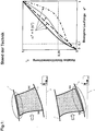
- the Fig. 1 1 shows, on the left side, a schematic representation of two blade configurations according to the prior art in the meridian plane formed by the radial direction r and the axial direction x. It is a rotor blade row 4 with a gap on the housing 1 (top), wherein the housing 1 is or in special cases also rotates and the blade row rotates about the machine axis 3.
- stator blades 5 It is also a row of stator blades 5 with a gap on the hub 2 (bottom), wherein the hub 2 rotates about the machine axis 3 or, in special cases, also rests and the row of blades 5 stands.
- the blade profile cut directly on the running gap of a rotor 4 or stator 5 is designed such that the profile load and thus the profile curvature in the region of the leading edge does not exceed a certain level, because conventional design rules based on considerations of the nature of two-dimensional flows around profiles recommend this.
- the right side of the Fig. 1 shows different, the prior art corresponding distributions of the skeleton line curvature in the profile section directly on the running gap, shown as a relative curvature ⁇ * over the related run length s * (for definitions see Fig. 3 ).
- This category includes the so-called CDA (controlled diffusion aerofoils) US 4431376 A , From an aerodynamic point of view, the CDA aims for a moderate profile frontload.
- CDA controlled diffusion aerofoils
- the present invention has for its object to provide a fluid flow machine of the type mentioned, which while avoiding the disadvantages of In the prior art, a very effective influencing of the edge flow is achieved by an excessive skeleton curve curvature in the region of the front edge of the blade profile cuts located near the running gap.
- a fluid power machine comprising a blade disposed in a main flow path bounded by a hub and a housing, wherein a gap is provided between an end of the blade and the main flow path boundary, hub or housing, and thus a free blade end is formed, wherein in at least one blade profile streamline section in the area between the gap and one
- the Fig.2 gives a precise definition of the meridional flow lines and the streamline profile sections.
- the mean meridional flow line 7 is formed by the geometric center of an annular channel 6. If one establishes a normal at each location of the middle streamline 7, one obtains the course of the ring channel width W along the flow path and, on the other hand, a number of normals with whose help further meridional flow lines result with the same relative subdivision in the direction of the channel height.
- the intersection of a meridional streamline with a blade results in a streamline profile intersection.
- the respective skeleton line type for a streamline profile intersection is defined in relative representation by means of the relative curvature ⁇ * and the related run length s *, see Figure 3 , The figure shows a streamline profile section of the blade on a meridian flow surface (um plane).
- the inclination angle ⁇ p and the run length s P covered up to this point are determined in all points of the skeleton line.
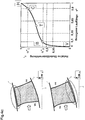
- the Fig. 4a shows a family of inventive crevices near the profile skeleton curves. They are characterized in that the relative skeleton curve curvature ⁇ * always has values greater than or equal to 0.35 for related run lengths of s *> 0.1.
- Fig. 4a The distribution shown shows the special case according to the invention of a change of the skeleton curve curvature sign.
- the skeleton line is convexly curved towards the profile suction side in a part of the run length s * and concave in a lower part of the run length s *, as is the case if values of ⁇ *> 1 at least in part of the run length s * are provided.
- the excessive leakage of the profile leading edge region in the vicinity of the running gap influences the leakage flows occurring at the running gap.
- values of the relative skeleton curve curvature ⁇ * of greater than or equal to 0.35 or even greater than 0.5 or in special cases greater than or equal to 0.65 or in extreme cases greater than 1.0 already at a relative run length of s * 0.1.
- a curvature distribution ⁇ * f (s *), the high gradient at the starting point A, starting in the further course of the point B approaches with decreasing gradient.
- the Fig. 4b shows an also according to the invention Schar of Skelettlinienwölbungsveranderen, which is also suitable for aerodynamically highly loaded profiles.
- the curvature at point T changes its sign.
- an S-shaped skeleton line curvature distribution results according to the invention, corresponding to FIG Fig. 4b shown crowd.
- the value ⁇ * C provided at s * 0.9 and thus the position of the point C is restricted.
- particularly favorable solutions result if ⁇ * C ⁇ * B + 0.75 (1- ⁇ * B ).
- the skeleton line curvature distribution according to the invention is to be provided in at least one vane stream section in the region between the gap and a vane section at 5% of the main flow path width (0.05 W).
- This skeleton line curvature distribution can be provided directly at the gap, but according to the invention must be provided at least within the 5% of the main flow path width W adjacent to the gap.
- Pumps and fans have an edge flow control which, while maintaining the same stability, can increase the efficiency of each stage by approximately 0.3%.
- a reduction in the number of blades of up to 20% is possible.
- the inventive concept is applicable to different types of turbomachines and, depending on the degree of utilization of the concept, leads to reductions in costs and weight for the turbomachine of 2% to 10%.
Claims (11)
- Machine à écoulement comprenant une aube, disposée dans une voie d'écoulement principale (6) bordée par un moyeu (2) et un carter (1), sachant qu'une fente (10) est constituée entre une extrémité de l'aube et une bordure de la voie d'écoulement principale formée par un moyeu (2) ou un carter (1) et qu'est constituée ainsi une extrémité d'aube libre, sachant que dans au moins une coupe de la ligne d'écoulement du profil d'aube dans la zone située entre la fente (10) et une coupe de l'aube à la distance de 30 % de la largeur de la voie d'écoulement principale W par rapport à la fente (10) est prévue une répartition de la courbure de la ligne moyenne qui présente, pour une longueur de course rapportée de s* = 0,1, une valeur excédentaire de la courbure relative de la ligne moyenne d'au moins α* = 0,35, s* représentant la longueur de course locale rapportée à la longueur de course totale de la ligne moyenne du profil et α* étant conçue sous forme de changement d'angle de la ligne moyenne atteint par rapport à la courbure totale de la ligne moyenne, du bord d'attaque jusqu'à une longueur de course s* rapportée, sachant que la répartition de la courbure de la ligne moyenne commence, dans cette représentation, au point du bord d'attaque V de l'aube (s* = 0, α* = 0) et se termine au point du bord de fuite H de l'aube (s* = 1, α* = 1) et sachant que la courbure totale de la ligne moyenne est définie par le changement d'angle de la ligne moyenne, du point du bord d'attaque (V) jusqu'au point du bord de fuite (H) de l'aube, caractérisée en ce qu'une répartition de la courbure de la ligne moyenne est prévue au moins dans les 5 % de la largeur de la voie d'écoulement principale jouxtant la fente, ladite répartition présente, pour une longueur de course rapportée de s* = 0,1 une valeur surélevée de la courbure relative de la ligne moyenne d'au moins α* = 0,35.
- Machine à écoulement selon la revendication n° 1, caractérisée en ce qu'est prévue au moins directement sur la fente (10) une répartition de la courbure de la ligne moyenne qui présente, pour une longueur de course rapportée de s* = 0,1, une valeur surélevée de la courbure relative de la ligne moyenne d'au moins α* = 0,35.
- Machine à écoulement selon une des revendications n° 1 ou n° 2, caractérisée en ce qu'est prévue, pour une longueur de course rapportée de s* = 0,1, une valeur surélevée de la courbure relative de la ligne moyenne d'au moins α* = 0,50.
- Machine à écoulement selon une des revendications n° 1 à n° 3, caractérisée en ce que la répartition de la courbure de la ligne moyenne commence avec un gradient élevé au point du bord d'attaque V et se rapproche par la suite de la longueur de course rapportée s* = 0,1 avec un gradient décroissant.
- Machine à écoulement selon une des revendications n° 1 à n° 4, caractérisée en ce que la répartition de la courbure de la ligne moyenne se poursuit, de la longueur de course rapportée s* = 0,1 vers le point du bord de fuite H, sans coude et avec un gradient décroissant ou constant jusqu'au point du bord de fuite H, sachant que le point de courbure maximum de la répartition de la courbure de la ligne moyenne est prévue dans la plage telle que 0< = s*< = 0,2.
- Machine à écoulement selon une des revendications n° 1 à n° 4, caractérisée en ce que la répartition de la courbure de la ligne moyenne se poursuit, de la longueur de course rapportée s* = 0,1 vers le point du bord de fuite H, sans coude tout d'abord avec un gradient de plus en plus faible et, à partir d'un point T au niveau duquel la courbure change de signe, présente à nouveau des gradients croissants pour au moins une partie de la plage telle que 0,1 < = s*< = 1.
- Machine à écoulement selon la revendication n° 6, caractérisée en ce que la répartition de la courbure de la ligne moyenne n'a qu'un seul changement de signe de courbure et présente un tracé en forme de S.
- Machine à écoulement selon une des revendications n° 6 et n° 7, caractérisée en ce que le point T du premier changement de signe de courbure est prévu dans une plage telle que 0,35< = s*< = 0,65.
- Machine à écoulement selon une des revendications n° 1 à n° 8, caractérisée en ce que la répartition de la courbure de la ligne moyenne s'étend dans au moins une partie de la plage telle que 0,1< = s*< = 1 pour des valeurs constantes de la courbure relative de la ligne moyenne α*.
- Machine à écoulement selon une des revendications n° 1 à n° 9, caractérisée en ce que la répartition de la courbure de la ligne moyenne présente, pour une longueur de course rapportée de s* = 0,9, une valeur de la courbure relative de la ligne moyenne de α* < α*(s* = 0,1) + 0,75 (1 - α*(s* = 0,1)).
- Machine à écoulement selon une des revendications n° 1 à n° 10, caractérisée en ce que la répartition de la courbure de la ligne moyenne s'étend courbée, courbée par sections ou droite par sections et présente, ainsi, un nombre quelconque de coudes entre le point du bord d'attaque V et le point du bord de fuite H.
Applications Claiming Priority (1)
| Application Number | Priority Date | Filing Date | Title |
|---|---|---|---|
| DE102009033593A DE102009033593A1 (de) | 2009-07-17 | 2009-07-17 | Triebwerkschaufel mit überhöhter Vorderkantenbelastung |
Publications (3)
| Publication Number | Publication Date |
|---|---|
| EP2275643A2 EP2275643A2 (fr) | 2011-01-19 |
| EP2275643A3 EP2275643A3 (fr) | 2017-10-04 |
| EP2275643B1 true EP2275643B1 (fr) | 2018-12-26 |
Family
ID=42278932
Family Applications (1)
| Application Number | Title | Priority Date | Filing Date |
|---|---|---|---|
| EP10005471.7A Not-in-force EP2275643B1 (fr) | 2009-07-17 | 2010-05-26 | Aube de moteur dotée d'une charge de rebords avant surélevée |
Country Status (3)
| Country | Link |
|---|---|
| US (1) | US8439646B2 (fr) |
| EP (1) | EP2275643B1 (fr) |
| DE (1) | DE102009033593A1 (fr) |
Families Citing this family (10)
| Publication number | Priority date | Publication date | Assignee | Title |
|---|---|---|---|---|
| CN102113900B (zh) * | 2010-01-05 | 2015-07-15 | 深圳迈瑞生物医疗电子股份有限公司 | 彩色血流动态帧相关方法和装置 |
| DE102014203605A1 (de) | 2014-02-27 | 2015-08-27 | Rolls-Royce Deutschland Ltd & Co Kg | Schaufelreihengruppe |
| JP6468414B2 (ja) * | 2014-08-12 | 2019-02-13 | 株式会社Ihi | 圧縮機静翼、軸流圧縮機、及びガスタービン |
| US9797267B2 (en) * | 2014-12-19 | 2017-10-24 | Siemens Energy, Inc. | Turbine airfoil with optimized airfoil element angles |
| DE102016115868A1 (de) * | 2016-08-26 | 2018-03-01 | Rolls-Royce Deutschland Ltd & Co Kg | Strömungsarbeitsmaschine mit hohem Ausnutzungsgrad |
| GB201719539D0 (en) | 2017-11-24 | 2018-01-10 | Rolls Royce Plc | Gas Turbine Engine |
| GB201719538D0 (en) | 2017-11-24 | 2018-01-10 | Rolls Royce Plc | Gas turbine engine |
| EP3730801A4 (fr) | 2017-12-20 | 2021-05-05 | Ihi Corporation | Ventilateur et aube de stator de compresseur |
| CN109058161B (zh) * | 2018-09-27 | 2023-08-29 | 美的集团股份有限公司 | 轴流风轮及空调室外机 |
| IT202000005146A1 (it) * | 2020-03-11 | 2021-09-11 | Ge Avio Srl | Motore a turbina con profilo aerodinamico avente alta accelerazione e bassa curva di paletta |
Family Cites Families (8)
| Publication number | Priority date | Publication date | Assignee | Title |
|---|---|---|---|---|
| US4431376A (en) | 1980-10-27 | 1984-02-14 | United Technologies Corporation | Airfoil shape for arrays of airfoils |
| US4961686A (en) * | 1989-02-17 | 1990-10-09 | General Electric Company | F.O.D.-resistant blade |
| US5167489A (en) * | 1991-04-15 | 1992-12-01 | General Electric Company | Forward swept rotor blade |
| US5525038A (en) * | 1994-11-04 | 1996-06-11 | United Technologies Corporation | Rotor airfoils to control tip leakage flows |
| FR2797658B1 (fr) * | 1999-08-18 | 2002-08-23 | Snecma | Aube de turbine a profil ameliore |
| US7204676B2 (en) * | 2004-05-14 | 2007-04-17 | Pratt & Whitney Canada Corp. | Fan blade curvature distribution for high core pressure ratio fan |
| DE102005042115A1 (de) * | 2005-09-05 | 2007-03-08 | Rolls-Royce Deutschland Ltd & Co Kg | Schaufel einer Strömungsarbeitsmaschine mit blockweise definierter Profilskelettlinie |
| DE102006055869A1 (de) * | 2006-11-23 | 2008-05-29 | Rolls-Royce Deutschland Ltd & Co Kg | Schaufelblattdesign für die Lauf- und Leitschaufeln einer Turbomaschine |
-
2009
- 2009-07-17 DE DE102009033593A patent/DE102009033593A1/de not_active Withdrawn
-
2010
- 2010-05-26 EP EP10005471.7A patent/EP2275643B1/fr not_active Not-in-force
- 2010-06-14 US US12/815,122 patent/US8439646B2/en not_active Expired - Fee Related
Non-Patent Citations (1)
| Title |
|---|
| None * |
Also Published As
| Publication number | Publication date |
|---|---|
| EP2275643A2 (fr) | 2011-01-19 |
| US20110014057A1 (en) | 2011-01-20 |
| US8439646B2 (en) | 2013-05-14 |
| DE102009033593A1 (de) | 2011-01-20 |
| EP2275643A3 (fr) | 2017-10-04 |
Similar Documents
| Publication | Publication Date | Title |
|---|---|---|
| EP2275643B1 (fr) | Aube de moteur dotée d'une charge de rebords avant surélevée | |
| EP1657401B1 (fr) | Turbomachine comprenant des aubes avec une augmentation de la longueur des chordes du profil dans l'extrémité de l'aube | |
| EP2025945B1 (fr) | Machine de traitement des écoulements dotée d'un creux de paroi de canal de ceinture | |
| EP2096260B1 (fr) | Turbomachine comprenant des ensembles rotor ayant un faible angle de déviation du fluide en sortie | |
| EP2261463B1 (fr) | Turbomachine avec groupe d'étages aubagés | |
| EP2096316B1 (fr) | Structuration de boîtier pour compresseur axial dans la zone du moyeu | |
| EP2463480B1 (fr) | Aube avec profile hybride | |
| EP1798375B1 (fr) | Profil d'aube pour aubes statoriques variables | |
| EP2003292B1 (fr) | Machine de travail fluidique avec virole d'aube dotée d'un rebord | |
| EP1760321A2 (fr) | Pale d'une turbomachine | |
| EP2228542B1 (fr) | Turbo compresseur ou pompe avec injection de fluide pour influencer la couche limite | |
| EP2761137B1 (fr) | Pale d'une rangée de pales de rotor ou de stator pour une turbomachine | |
| EP1632662A2 (fr) | Turbomachine avec soutirage | |
| EP2194232A2 (fr) | Turbomachine dotée d'une barrière à couche frontière sur la paroi latérale | |
| EP2913478B1 (fr) | Aubes en tandem d'une turbomachine | |
| EP2947270B3 (fr) | Groupe de série d'aubes | |
| EP2180195A2 (fr) | Turbomachine avec contrôle du jeu des aubes | |
| EP1998049A2 (fr) | Aube de machine de travail d'écoulement doté d'une conception à plusieurs profiles | |
| EP2913479B1 (fr) | Aubes en tandem d'une turbomachine | |
| EP1865148B1 (fr) | Machine de traitement des écoulements dotée de rotors de distribution d'énergie supérieure spécifique | |
| DE10205363A1 (de) | Gasturbine | |
| EP1953340B1 (fr) | Machine de traitement des écoulements et aube de rotor d'une machine de traitement des écoulements |
Legal Events
| Date | Code | Title | Description |
|---|---|---|---|
| PUAI | Public reference made under article 153(3) epc to a published international application that has entered the european phase |
Free format text: ORIGINAL CODE: 0009012 |
|
| AK | Designated contracting states |
Kind code of ref document: A2 Designated state(s): AL AT BE BG CH CY CZ DE DK EE ES FI FR GB GR HR HU IE IS IT LI LT LU LV MC MK MT NL NO PL PT RO SE SI SK SM TR |
|
| AX | Request for extension of the european patent |
Extension state: BA ME RS |
|
| PUAL | Search report despatched |
Free format text: ORIGINAL CODE: 0009013 |
|
| AK | Designated contracting states |
Kind code of ref document: A3 Designated state(s): AL AT BE BG CH CY CZ DE DK EE ES FI FR GB GR HR HU IE IS IT LI LT LU LV MC MK MT NL NO PL PT RO SE SI SK SM TR |
|
| AX | Request for extension of the european patent |
Extension state: BA ME RS |
|
| RIC1 | Information provided on ipc code assigned before grant |
Ipc: F01D 5/14 20060101AFI20170830BHEP Ipc: F01D 5/20 20060101ALI20170830BHEP |
|
| STAA | Information on the status of an ep patent application or granted ep patent |
Free format text: STATUS: REQUEST FOR EXAMINATION WAS MADE |
|
| 17P | Request for examination filed |
Effective date: 20180313 |
|
| RBV | Designated contracting states (corrected) |
Designated state(s): AL AT BE BG CH CY CZ DE DK EE ES FI FR GB GR HR HU IE IS IT LI LT LU LV MC MK MT NL NO PL PT RO SE SI SK SM TR |
|
| GRAP | Despatch of communication of intention to grant a patent |
Free format text: ORIGINAL CODE: EPIDOSNIGR1 |
|
| STAA | Information on the status of an ep patent application or granted ep patent |
Free format text: STATUS: GRANT OF PATENT IS INTENDED |
|
| INTG | Intention to grant announced |
Effective date: 20180601 |
|
| GRAS | Grant fee paid |
Free format text: ORIGINAL CODE: EPIDOSNIGR3 |
|
| RIN1 | Information on inventor provided before grant (corrected) |
Inventor name: GUEMMER, VOLKER DR. |
|
| GRAA | (expected) grant |
Free format text: ORIGINAL CODE: 0009210 |
|
| STAA | Information on the status of an ep patent application or granted ep patent |
Free format text: STATUS: THE PATENT HAS BEEN GRANTED |
|
| AK | Designated contracting states |
Kind code of ref document: B1 Designated state(s): AL AT BE BG CH CY CZ DE DK EE ES FI FR GB GR HR HU IE IS IT LI LT LU LV MC MK MT NL NO PL PT RO SE SI SK SM TR |
|
| REG | Reference to a national code |
Ref country code: GB Ref legal event code: FG4D Free format text: NOT ENGLISH |
|
| REG | Reference to a national code |
Ref country code: CH Ref legal event code: EP |
|
| REG | Reference to a national code |
Ref country code: AT Ref legal event code: REF Ref document number: 1081694 Country of ref document: AT Kind code of ref document: T Effective date: 20190115 |
|
| REG | Reference to a national code |
Ref country code: DE Ref legal event code: R096 Ref document number: 502010015649 Country of ref document: DE |
|
| REG | Reference to a national code |
Ref country code: IE Ref legal event code: FG4D Free format text: LANGUAGE OF EP DOCUMENT: GERMAN |
|
| PG25 | Lapsed in a contracting state [announced via postgrant information from national office to epo] |
Ref country code: NO Free format text: LAPSE BECAUSE OF FAILURE TO SUBMIT A TRANSLATION OF THE DESCRIPTION OR TO PAY THE FEE WITHIN THE PRESCRIBED TIME-LIMIT Effective date: 20190326 Ref country code: BG Free format text: LAPSE BECAUSE OF FAILURE TO SUBMIT A TRANSLATION OF THE DESCRIPTION OR TO PAY THE FEE WITHIN THE PRESCRIBED TIME-LIMIT Effective date: 20190326 Ref country code: LT Free format text: LAPSE BECAUSE OF FAILURE TO SUBMIT A TRANSLATION OF THE DESCRIPTION OR TO PAY THE FEE WITHIN THE PRESCRIBED TIME-LIMIT Effective date: 20181226 Ref country code: FI Free format text: LAPSE BECAUSE OF FAILURE TO SUBMIT A TRANSLATION OF THE DESCRIPTION OR TO PAY THE FEE WITHIN THE PRESCRIBED TIME-LIMIT Effective date: 20181226 Ref country code: HR Free format text: LAPSE BECAUSE OF FAILURE TO SUBMIT A TRANSLATION OF THE DESCRIPTION OR TO PAY THE FEE WITHIN THE PRESCRIBED TIME-LIMIT Effective date: 20181226 Ref country code: LV Free format text: LAPSE BECAUSE OF FAILURE TO SUBMIT A TRANSLATION OF THE DESCRIPTION OR TO PAY THE FEE WITHIN THE PRESCRIBED TIME-LIMIT Effective date: 20181226 |
|
| REG | Reference to a national code |
Ref country code: NL Ref legal event code: MP Effective date: 20181226 |
|
| REG | Reference to a national code |
Ref country code: LT Ref legal event code: MG4D |
|
| PG25 | Lapsed in a contracting state [announced via postgrant information from national office to epo] |
Ref country code: AL Free format text: LAPSE BECAUSE OF FAILURE TO SUBMIT A TRANSLATION OF THE DESCRIPTION OR TO PAY THE FEE WITHIN THE PRESCRIBED TIME-LIMIT Effective date: 20181226 Ref country code: SE Free format text: LAPSE BECAUSE OF FAILURE TO SUBMIT A TRANSLATION OF THE DESCRIPTION OR TO PAY THE FEE WITHIN THE PRESCRIBED TIME-LIMIT Effective date: 20181226 Ref country code: GR Free format text: LAPSE BECAUSE OF FAILURE TO SUBMIT A TRANSLATION OF THE DESCRIPTION OR TO PAY THE FEE WITHIN THE PRESCRIBED TIME-LIMIT Effective date: 20190327 |
|
| PG25 | Lapsed in a contracting state [announced via postgrant information from national office to epo] |
Ref country code: NL Free format text: LAPSE BECAUSE OF FAILURE TO SUBMIT A TRANSLATION OF THE DESCRIPTION OR TO PAY THE FEE WITHIN THE PRESCRIBED TIME-LIMIT Effective date: 20181226 |
|
| PG25 | Lapsed in a contracting state [announced via postgrant information from national office to epo] |
Ref country code: ES Free format text: LAPSE BECAUSE OF FAILURE TO SUBMIT A TRANSLATION OF THE DESCRIPTION OR TO PAY THE FEE WITHIN THE PRESCRIBED TIME-LIMIT Effective date: 20181226 Ref country code: PL Free format text: LAPSE BECAUSE OF FAILURE TO SUBMIT A TRANSLATION OF THE DESCRIPTION OR TO PAY THE FEE WITHIN THE PRESCRIBED TIME-LIMIT Effective date: 20181226 Ref country code: IT Free format text: LAPSE BECAUSE OF FAILURE TO SUBMIT A TRANSLATION OF THE DESCRIPTION OR TO PAY THE FEE WITHIN THE PRESCRIBED TIME-LIMIT Effective date: 20181226 Ref country code: CZ Free format text: LAPSE BECAUSE OF FAILURE TO SUBMIT A TRANSLATION OF THE DESCRIPTION OR TO PAY THE FEE WITHIN THE PRESCRIBED TIME-LIMIT Effective date: 20181226 Ref country code: PT Free format text: LAPSE BECAUSE OF FAILURE TO SUBMIT A TRANSLATION OF THE DESCRIPTION OR TO PAY THE FEE WITHIN THE PRESCRIBED TIME-LIMIT Effective date: 20190426 |
|
| PG25 | Lapsed in a contracting state [announced via postgrant information from national office to epo] |
Ref country code: IS Free format text: LAPSE BECAUSE OF FAILURE TO SUBMIT A TRANSLATION OF THE DESCRIPTION OR TO PAY THE FEE WITHIN THE PRESCRIBED TIME-LIMIT Effective date: 20190426 Ref country code: SK Free format text: LAPSE BECAUSE OF FAILURE TO SUBMIT A TRANSLATION OF THE DESCRIPTION OR TO PAY THE FEE WITHIN THE PRESCRIBED TIME-LIMIT Effective date: 20181226 Ref country code: SM Free format text: LAPSE BECAUSE OF FAILURE TO SUBMIT A TRANSLATION OF THE DESCRIPTION OR TO PAY THE FEE WITHIN THE PRESCRIBED TIME-LIMIT Effective date: 20181226 Ref country code: EE Free format text: LAPSE BECAUSE OF FAILURE TO SUBMIT A TRANSLATION OF THE DESCRIPTION OR TO PAY THE FEE WITHIN THE PRESCRIBED TIME-LIMIT Effective date: 20181226 Ref country code: RO Free format text: LAPSE BECAUSE OF FAILURE TO SUBMIT A TRANSLATION OF THE DESCRIPTION OR TO PAY THE FEE WITHIN THE PRESCRIBED TIME-LIMIT Effective date: 20181226 |
|
| REG | Reference to a national code |
Ref country code: DE Ref legal event code: R097 Ref document number: 502010015649 Country of ref document: DE |
|
| PG25 | Lapsed in a contracting state [announced via postgrant information from national office to epo] |
Ref country code: DK Free format text: LAPSE BECAUSE OF FAILURE TO SUBMIT A TRANSLATION OF THE DESCRIPTION OR TO PAY THE FEE WITHIN THE PRESCRIBED TIME-LIMIT Effective date: 20181226 |
|
| PLBE | No opposition filed within time limit |
Free format text: ORIGINAL CODE: 0009261 |
|
| STAA | Information on the status of an ep patent application or granted ep patent |
Free format text: STATUS: NO OPPOSITION FILED WITHIN TIME LIMIT |
|
| 26N | No opposition filed |
Effective date: 20190927 |
|
| REG | Reference to a national code |
Ref country code: CH Ref legal event code: PL |
|
| PG25 | Lapsed in a contracting state [announced via postgrant information from national office to epo] |
Ref country code: LI Free format text: LAPSE BECAUSE OF NON-PAYMENT OF DUE FEES Effective date: 20190531 Ref country code: CH Free format text: LAPSE BECAUSE OF NON-PAYMENT OF DUE FEES Effective date: 20190531 Ref country code: MC Free format text: LAPSE BECAUSE OF FAILURE TO SUBMIT A TRANSLATION OF THE DESCRIPTION OR TO PAY THE FEE WITHIN THE PRESCRIBED TIME-LIMIT Effective date: 20181226 |
|
| REG | Reference to a national code |
Ref country code: BE Ref legal event code: MM Effective date: 20190531 |
|
| PG25 | Lapsed in a contracting state [announced via postgrant information from national office to epo] |
Ref country code: SI Free format text: LAPSE BECAUSE OF FAILURE TO SUBMIT A TRANSLATION OF THE DESCRIPTION OR TO PAY THE FEE WITHIN THE PRESCRIBED TIME-LIMIT Effective date: 20181226 Ref country code: LU Free format text: LAPSE BECAUSE OF NON-PAYMENT OF DUE FEES Effective date: 20190526 |
|
| PG25 | Lapsed in a contracting state [announced via postgrant information from national office to epo] |
Ref country code: TR Free format text: LAPSE BECAUSE OF FAILURE TO SUBMIT A TRANSLATION OF THE DESCRIPTION OR TO PAY THE FEE WITHIN THE PRESCRIBED TIME-LIMIT Effective date: 20181226 |
|
| PG25 | Lapsed in a contracting state [announced via postgrant information from national office to epo] |
Ref country code: IE Free format text: LAPSE BECAUSE OF NON-PAYMENT OF DUE FEES Effective date: 20190526 |
|
| PG25 | Lapsed in a contracting state [announced via postgrant information from national office to epo] |
Ref country code: BE Free format text: LAPSE BECAUSE OF NON-PAYMENT OF DUE FEES Effective date: 20190531 |
|
| PGFP | Annual fee paid to national office [announced via postgrant information from national office to epo] |
Ref country code: FR Payment date: 20200528 Year of fee payment: 11 |
|
| REG | Reference to a national code |
Ref country code: AT Ref legal event code: MM01 Ref document number: 1081694 Country of ref document: AT Kind code of ref document: T Effective date: 20190526 |
|
| PGFP | Annual fee paid to national office [announced via postgrant information from national office to epo] |
Ref country code: GB Payment date: 20200528 Year of fee payment: 11 |
|
| PGFP | Annual fee paid to national office [announced via postgrant information from national office to epo] |
Ref country code: DE Payment date: 20200728 Year of fee payment: 11 |
|
| PG25 | Lapsed in a contracting state [announced via postgrant information from national office to epo] |
Ref country code: AT Free format text: LAPSE BECAUSE OF NON-PAYMENT OF DUE FEES Effective date: 20190526 |
|
| PG25 | Lapsed in a contracting state [announced via postgrant information from national office to epo] |
Ref country code: CY Free format text: LAPSE BECAUSE OF FAILURE TO SUBMIT A TRANSLATION OF THE DESCRIPTION OR TO PAY THE FEE WITHIN THE PRESCRIBED TIME-LIMIT Effective date: 20181226 |
|
| PG25 | Lapsed in a contracting state [announced via postgrant information from national office to epo] |
Ref country code: MT Free format text: LAPSE BECAUSE OF FAILURE TO SUBMIT A TRANSLATION OF THE DESCRIPTION OR TO PAY THE FEE WITHIN THE PRESCRIBED TIME-LIMIT Effective date: 20181226 Ref country code: HU Free format text: LAPSE BECAUSE OF FAILURE TO SUBMIT A TRANSLATION OF THE DESCRIPTION OR TO PAY THE FEE WITHIN THE PRESCRIBED TIME-LIMIT; INVALID AB INITIO Effective date: 20100526 |
|
| REG | Reference to a national code |
Ref country code: DE Ref legal event code: R119 Ref document number: 502010015649 Country of ref document: DE |
|
| GBPC | Gb: european patent ceased through non-payment of renewal fee |
Effective date: 20210526 |
|
| REG | Reference to a national code |
Ref country code: DE Ref legal event code: R082 Ref document number: 502010015649 Country of ref document: DE |
|
| PG25 | Lapsed in a contracting state [announced via postgrant information from national office to epo] |
Ref country code: GB Free format text: LAPSE BECAUSE OF NON-PAYMENT OF DUE FEES Effective date: 20210526 Ref country code: DE Free format text: LAPSE BECAUSE OF NON-PAYMENT OF DUE FEES Effective date: 20211201 |
|
| PG25 | Lapsed in a contracting state [announced via postgrant information from national office to epo] |
Ref country code: FR Free format text: LAPSE BECAUSE OF NON-PAYMENT OF DUE FEES Effective date: 20210531 |
|
| PG25 | Lapsed in a contracting state [announced via postgrant information from national office to epo] |
Ref country code: MK Free format text: LAPSE BECAUSE OF FAILURE TO SUBMIT A TRANSLATION OF THE DESCRIPTION OR TO PAY THE FEE WITHIN THE PRESCRIBED TIME-LIMIT Effective date: 20181226 |