EP0984477B1 - Verfahren zur Herstellung eines Jochs eines Magnetauslösers und Vorrichtung zur Durchführung dieses Verfahrens - Google Patents
Verfahren zur Herstellung eines Jochs eines Magnetauslösers und Vorrichtung zur Durchführung dieses Verfahrens Download PDFInfo
- Publication number
- EP0984477B1 EP0984477B1 EP99810731A EP99810731A EP0984477B1 EP 0984477 B1 EP0984477 B1 EP 0984477B1 EP 99810731 A EP99810731 A EP 99810731A EP 99810731 A EP99810731 A EP 99810731A EP 0984477 B1 EP0984477 B1 EP 0984477B1
- Authority
- EP
- European Patent Office
- Prior art keywords
- yoke
- capacitance
- spacing
- laminations
- value
- Prior art date
- Legal status (The legal status is an assumption and is not a legal conclusion. Google has not performed a legal analysis and makes no representation as to the accuracy of the status listed.)
- Expired - Lifetime
Links
- 238000004519 manufacturing process Methods 0.000 title claims abstract description 14
- 238000000034 method Methods 0.000 title claims description 20
- 238000003466 welding Methods 0.000 claims description 9
- 239000003990 capacitor Substances 0.000 claims description 6
- 238000005304 joining Methods 0.000 claims description 3
- 238000003475 lamination Methods 0.000 claims 22
- 238000009434 installation Methods 0.000 claims 3
- 230000003534 oscillatory effect Effects 0.000 claims 1
- 230000007246 mechanism Effects 0.000 abstract description 2
- 239000002184 metal Substances 0.000 abstract 3
- 238000005259 measurement Methods 0.000 description 5
- 230000004907 flux Effects 0.000 description 4
- 230000008569 process Effects 0.000 description 4
- 125000006850 spacer group Chemical group 0.000 description 3
- 230000005540 biological transmission Effects 0.000 description 2
- 230000032683 aging Effects 0.000 description 1
- 238000004140 cleaning Methods 0.000 description 1
- 230000008878 coupling Effects 0.000 description 1
- 238000010168 coupling process Methods 0.000 description 1
- 238000005859 coupling reaction Methods 0.000 description 1
- 230000001419 dependent effect Effects 0.000 description 1
- 238000006073 displacement reaction Methods 0.000 description 1
- 230000001788 irregular Effects 0.000 description 1
- 238000003825 pressing Methods 0.000 description 1
- 230000009467 reduction Effects 0.000 description 1
- 230000004044 response Effects 0.000 description 1
- 238000012876 topography Methods 0.000 description 1
Images

Classifications
-
- H—ELECTRICITY
- H01—ELECTRIC ELEMENTS
- H01H—ELECTRIC SWITCHES; RELAYS; SELECTORS; EMERGENCY PROTECTIVE DEVICES
- H01H71/00—Details of the protective switches or relays covered by groups H01H73/00 - H01H83/00
- H01H71/10—Operating or release mechanisms
- H01H71/12—Automatic release mechanisms with or without manual release
- H01H71/24—Electromagnetic mechanisms
- H01H71/32—Electromagnetic mechanisms having permanently magnetised part
- H01H71/327—Manufacturing or calibrating methods, e.g. air gap treatments
Definitions
- a method for producing a two fixed plates containing yoke of a preferably in one Residual current circuit breaker (Fl-switch) deployable magnetic release after the The preamble of claim 1.
- a yoke is used to guide a constant magnetic flux from a permanent magnet to a movable armature of the magnetic release. Will the magnetic flux through one delivered by a trip coil and about a fault current weakened signal to be returned, so is the biased spring lifted anchor lifted from the yoke and then triggers a power transmission member.
- the power transmission member acts on a switching mechanism, which causes an opening of the contact arrangement of the Fl-switch.
- the invention relates to a prior art, as in EP 0786 789 A1 is described.
- a specified in this prior art yoke for one in a Fl-switch built-in magnetic release has essentially two fixed arranged yoke plates, which by means of web-shaped Connecting points are joined together, and between which turns out to be magnetic poorly conductive diaphragm is about 20 to 100 m thick air gap. Of the Air gap separates the two yoke plates forming a magnetic Resistance of predetermined size and prevents so that of a Permanent magnet fed into the magnetic circuit magnetic permanent flux shorted.
- the two yoke plates In the production of the known yoke, the two yoke plates usually each in one of two vertically stacked and Fixed against each other movable jaws. The sheets are then after interposition of Abstandshaltem to form the air gap led against each other and by attaching connection points in one Laser welding process fixed. The spacers are removed. The between the two yoke plates lying magnetic resistance vorweer size then through the air layer between the yoke plates and the geometric ones Dimensions of designed as welding points connecting points determined.
- spacers complicates and slows down the manufacturing process very important. In addition, it requires additional cleaning and Processing steps that additionally slow down the manufacturing process and expensive.
- the object is to provide a method of the type mentioned, with the in simple and inexpensive way yokes of high precision are manufactured and to provide an apparatus for carrying out this method.
- the inventive method detects with the measurement of the capacity of formed the two yoke plates and the intermediate air gap Condenser also indirectly the thickness of the air gap. Because of the analogy of electric and magnetic field is thus also the thickness of the Air gap dependent and for the release of the yoke containing Magnetic trigger decisive magnetic flux detected. By changing the air gap volume due to displacement of the yoke plates perpendicular to each other Thus, in the capacity measurement with high accuracy information about the average Jochblechabstand and thus also on the size of the magnetic River obtained, which is an extremely precise production of the yoke enable.
- the capacitance measurement used in the method according to the invention takes into account the turbulent surface topography of the yoke plates and thus delivers Direct image of the magnetic coupling between the yoke plates.
- she is insensitive to external disturbances, such as temperature, humidity, Air pressure, pollution, aging and / or EMC interference, has a high Resolution ( ⁇ 1nm) and a clear signal-response behavior and can because of short settling times (about 200 ⁇ s) are carried out very quickly.
- the device according to the invention for carrying out the method is characterized due to high flexibility and cycle times in the seconds range, for example 4 s. This is above all a consequence of the rapid feasibility of the capacitance measurement and the good usability of the determined capacity to form a manipulated variable in a control loop whose controlled variable is the thickness of the air gap or the middle one The distance between the yoke plates is.
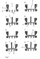
- the device shown in Figures 1 and 2 has two vertically stacked arranged jaws 1 and 2, of which the lower jaw. 1 fixed and the upper jaw 2 in the vertical direction (double arrow) slidably arranged.
- the way that the jaw 2 during a movement in the vertical direction, with the help of a not shown distance sensor can be detected.
- a three-point support 3 is empty before the device is put into operation (position A) and is loaded at the beginning of the manufacturing process with a yoke plate 4 (position B).
- position B By means of a pin formed as a positioning element 5, the yoke plate 4th with force against the three-point support 3 pressed (position C), and while maintaining the pressure in the lower jaw 1 fixed and aligned (position D).
- the Positioning element 5 is then moved away (position E) and the manufacturing device then loaded with a second yoke plate 6 (position F). This yoke plate will with the positioning element 5 with force against that on the three-point support. 3 supported yoke 4 pressed (position G) and while maintaining the pressure in the upper jaw 2 fixed (position H).
- two signal connections S 1 , S 3 or S 2 , S 4 of a capacitance measuring device 7 indicated in FIG. 3 are then guided from above or below to the yoke plates 4 and 6 (position J).
- the two signal terminals S 1 and S 2 serve to supply a signal generating the measured value to the yoke plates 4 and 6, whereas the two signal terminals S 3 and S 4 serve to receive a signal proportional to the signal from the yoke plates 4 and 6.
- the signal terminals S 3 and S 4 serving to receive the signal proportional to the measured value act on a controller 8 of a control circuit 9 which can be seen in FIG.
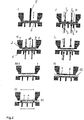
- the upper jaw 2 is now moved to form an air gap 10 between the two yoke plates 4 and 6 upwards (position K).
- position K the capacitance of the capacitor formed by the yoke plates 4, 6 and the air gap 10 in between is periodically measured periodically as a function of the yoke plate spacing. It can be seen from FIG. 3 that the measured capacitance C ist in each measuring period in the control circuit 9 is compared with a predetermined capacity setpoint lying between an upper limit C Sollmax and a lower limit C Sollmin .
- a signal y acting as a control variable is emitted to a device, not shown, for changing the distance between the two clamping jaws 1, 2, through which the clamping jaw 2 continues, and so the distance between the two yoke plates 4, 6 is changed (see Fig.3: distance correction y). If the measured capacitance and the setpoint agree, the capacitance measurement is terminated and the yoke plate clearance at the setpoint is initially kept constant.
- the signal connections of the capacitance measuring device are now moved away (position L). It is then made by moving the jaw 2, a distance correction y shrinkage (position M and Figure 3).
- a defined mounting value of the Jochblechabstandes is achieved by changing the initially held Jochblechabstands (position L) by a predetermined correction value. If this mounting value is set, the two yoke plates 4, 6 can be fixed by attaching connection points 11 (position O).
- the correction value y shrinkage is determined in such a way that, when attaching the connection points 11, a desired mean yoke plate spacing is established.
- connection points 11 are attached by means of a joining device 12 at the edge of the yoke plates 4, 6. If the connection points 11 are applied in a welding process, preferably in a laser welding process, then the initially held constant Jochblechabstand should be increased by the correction value y shrinkage , so as to compensate for the shrinkage occurring during welding reduction due to shrinkage (position N). But it can also serve as the mounting distance held initially constant Jochblechabstand (position L). The capacitance setpoint is then to be determined in such a way that the mean yoke plate spacing is set during the subsequent attachment of the connection points 11. When attaching the connection points 11 in a welding process, the capacitance setpoint should be smaller than the capacitance value of the capacitor, since then the shrinkage occurring during welding is taken into account.
- a capacitance measuring device 7 another device for determining the capacitance C ist of the capacitor formed by the yoke plates 4, 6 and the intermediate air gap 10 may also be used.
- a device may have a resonance frequency meter connected to the signal connections S 1 , S 2 , S 3 , S 4 and a computer connected downstream of the resonance frequency meter.
- the resonant frequency meter measures the resonant frequency of the capacitance C and an inductance of predetermined size containing resonant circuit.
- the computer determines from the resonance frequency measured by the resonance frequency, the capacitance C is , which is then - as described above - compared with the capacity setpoint.
Landscapes
- Engineering & Computer Science (AREA)
- Manufacturing & Machinery (AREA)
- Physics & Mathematics (AREA)
- Electromagnetism (AREA)
- Measurement Of Length, Angles, Or The Like Using Electric Or Magnetic Means (AREA)
- Breakers (AREA)
- Load-Engaging Elements For Cranes (AREA)
- Supporting Of Heads In Record-Carrier Devices (AREA)
- Manufacturing Cores, Coils, And Magnets (AREA)
- Electromagnets (AREA)
- Manufacture Of Motors, Generators (AREA)
Description
- 1, 2
- Klemmbacken
- 3
- Dreipunktauflage
- 4, 6
- Jochbleche
- 5
- Positionierelement
- 7
- Kapazitätsmessgerät
- 8
- Regler
- 9
- Regelkreis
- 10
- Luftspalt
- 11
- Verbindungspunkte
- 12
- Fügevorrichtung
- Cist
- gemessene Kapazität
- (CSollmax - CSollmin)
- Kapazitätssollwert
- y
- Abstandskorrektur
- YSchrumpf
- Abstandskorrekturwert für Schrumpfung
Claims (12)
- Verfahren zur Herstellung eines zwei feststehende Bleche (4, 6) enthaltenden Jochs eines vorzugsweise in einem Fehlerstrom-Schutzschalter einsetzbaren Magnetauslösers, bei dem die beiden Jochbleche (4, 6) unter Bildung eines Luftspalts (10) mit einem vorgegebenen Montageabstand zueinander gehalten und nach Anbringen von Verbindungspunkten (11) mit einem die magnetischen Eigenschaften des Auslösers bestimmenden mittleren Abstand zueinander fixiert werden, dadurch gekennzeichnet, dass vor dem Anbringen der Verbindungspunkte (11) Signalanschlüsse (S1, S2, S3, S4) einer Vorrichtung zur Ermittlung der Kapazität (Cist) eines von den Jochblechen (4, 6) und dem dazwischenliegenden Luftspalt (10) gebildeten Kondensators an die Jochbleche (4, 6) geführt werden, dass die Kapazität (Cist) in Abhängigkeit vom Jochblechabstand (y) periodisch ermittelt wird, dass die ermittelte Kapazität (Cist) in jeder Periode mit einem vorgegebenen Kapazitätssollwert (CSollmax - CSollmin) verglichen wird, und dass nach dem Erreichen des Sollwertes (CSollmax - CSollmin) das Ermitteln der Kapazität beendet und der beim Sollwert vorhandene Jochblechabstand zumindest vorübergehend konstant gehalten wird.
- Verfahren nach Anspruch 1, dadurch gekennzeichnet, dass der Montageabstand eingestellt wird durch Veränderung des konstant gehaltenen Jochblechabstands um einen vorgebenen Korrekturwert (ySchrumpf), wobei der Korrekturwert derart bestimmt ist, dass sich der mittlere Jochblechabstand beim nachfolgenden Anbringen der Verbindungspunkte (11) einstellt.
- Verfahren nach Anspruch 2, dadurch gekennzeichnet, dass beim Anbringen der Verbindungspunkte (11) in einem Schweissverfahren der konstante Jochblechabstand durch den Korrekturwert (ySchrumpf) vergrössert wird.
- Verfahren nach Anspruch 1, dadurch gekennzeichnet, dass der zunächst konstant gehaltene Jochblechabstand als Montageabstand dient und der Kapazitätssollwert (CSollmax - CSollmin) zugleich derart bestimmt ist, dass sich der mittlere Jochblechabstand beim nachfolgenden Anbringen der Verbindungspunkte (11) einstellt.
- Verfahren nach Anspruch 4, dadurch gekennzeichnet, dass beim Anbringen der Verbindungspunkte (11) in einem Schweissverfahren der Kapazitätssollwert (CSollmax - CSollmin) kleiner ist als der Kapazitätswert des Kondensators, bei dem die Jochbleche (4, 6) den mittleren Abstand aufweisen.
- Verfahren nach einem der Ansprüche 1 bis 5, dadurch gekennzeichnet, dass nach dem Erreichen des konstanten Jochblechabstands und vor dem Anbringen der Verbindungspunkte (11) die Signalanschlüsse (S1, S2, S3, S4) entfernt werden.
- Vorrichtung zur Durchführung des Verfahrens nach einem der Ansprüche 1 bis 6 mit je zwei gegeneinander verschiebbaren Klemmbacken (1, 2) zur Aufnahme je eines der beiden Jochbleche (4, 6) und mit einer die Verbindungspunkte (11) randseitig an den Jochblechen (4, 6) anbringenden Fügevorrichtung (12), dadurch gekennzeichnet, dass zusätzlich eine Vorrichtung zur Ermittlung der Kapazität (Cist) eines von den Jochblechen (4, 6) und dem dazwischenliegenden Luftspalt (10) gebildeten Kondensators vorgesehen ist mit an die Jochbleche (4, 6) führbaren Signalanschlüssen (S) zur Zuführung eines messwerterzeugenden Signals und zur Aufnahme eines messwertproportionalen Signals.
- Vorrichtung nach Anspruch 7, dadurch gekennzeichnet, dass die Vorrichtung zur Ermittlung der Kapazität ein Kapazitätsmessgerät (7) ist.
- Vorrichtung nach einem der Ansprüche 7 oder 8, dadurch gekennzeichnet, dass die der Aufnahme des messwertproportionalen Signals dienenden Signalanschlüsse auf einen Regler (8) eines Regelkreises (9) wirken, der den vor dem Anbringen der Verbindungspunkte (11) zunächst konstant gehaltenen Abstand der Jochbleche (4, 6) einstellt.
- Vorrichtung nach Anspruch 9, dadurch gekennzeichnet, dass im Regler (9) Mittel zum Vergleich der periodisch ermittelten Kapazität (Cist) mit dem vorgegebenen Kapazitätssollwert (CSollmax - CSollmin) vorgesehen sind sowie Mittel zur Bildung eines Stellsignals (y) an eine Vorrichtung zum Ändern des Abstandes der beiden Klemmbacken (1, 2).
- Vorrichtung nach Anspruch 10, dadurch gekennzeichnet, dass die Vorrichtung zur Ermittlung der Kapazität (Cist) einen mit den Signalanschlüsse (S1, S2, S3, S4) verbundenen Resonanzfrequenzmesser zum Messen der Resonanzfrequenz eines die Kapazität und eine Induktivität vorbestimmter Grösse enthaltenden Schwingkreises aufweist sowie einen dem Resonanzfrequenzmesser nachgeschalteten Computer zum Errechnen der zu ermittelnden Kapazität (Cist) aus der vom Resonanzfrequenzmesser gemessenen Resonanzfrequenz.
- Vorrichtung nach einem der Ansprüche 7 bis 11, dadurch gekennzeichnet, dass ferner eine Lagerung (3) zur Auflage des in der unteren Klemmbacke (1) festsetzbaren Jochblechs (4) sowie eine Positionierelement (5) zur Beaufschlagung jeweils eines der beiden Jochbleche (4, 6) mit Haltekraft beim Festsetzen des Jochbleches (4, 6) in der zugeordneten oberen (2) oder unteren Klemmbacke (1) vorgesehen sind.
Applications Claiming Priority (2)
| Application Number | Priority Date | Filing Date | Title |
|---|---|---|---|
| DE19839637A DE19839637A1 (de) | 1998-08-31 | 1998-08-31 | Verfahren zur Herstellung eines Jochs eines Magnetauslösers und Vorrichtung zur Durchführung dieses Verfahrens |
| DE19839637 | 1998-08-31 |
Publications (3)
| Publication Number | Publication Date |
|---|---|
| EP0984477A2 EP0984477A2 (de) | 2000-03-08 |
| EP0984477A3 EP0984477A3 (de) | 2001-03-28 |
| EP0984477B1 true EP0984477B1 (de) | 2005-03-30 |
Family
ID=7879319
Family Applications (1)
| Application Number | Title | Priority Date | Filing Date |
|---|---|---|---|
| EP99810731A Expired - Lifetime EP0984477B1 (de) | 1998-08-31 | 1999-08-13 | Verfahren zur Herstellung eines Jochs eines Magnetauslösers und Vorrichtung zur Durchführung dieses Verfahrens |
Country Status (4)
| Country | Link |
|---|---|
| EP (1) | EP0984477B1 (de) |
| AT (1) | ATE292323T1 (de) |
| DE (2) | DE19839637A1 (de) |
| ES (1) | ES2241253T3 (de) |
Families Citing this family (3)
| Publication number | Priority date | Publication date | Assignee | Title |
|---|---|---|---|---|
| EP2718953B1 (de) | 2011-06-06 | 2015-09-30 | Eti Elektroelement D.D. | Elektromagnetisches relais mit verbessertem bügel, insbesondere ein relais zur unterbrechung einer elektrischen schaltung bei differentialstrom sowie schalter mit einem solchen relais |
| DE102018204673B4 (de) * | 2018-03-27 | 2025-06-18 | Siemens Aktiengesellschaft | Verfahren zur Herstellung eines Magnetjochs |
| EP4625464A1 (de) | 2024-03-28 | 2025-10-01 | Hager-Electro Sas | Verfahren zur oberflächenbehandlung eines ankers eines elektromagnetischen auslösers, beschlag und elektromagnetischer auslöser |
Family Cites Families (8)
| Publication number | Priority date | Publication date | Assignee | Title |
|---|---|---|---|---|
| AT281965B (de) * | 1967-01-20 | 1970-06-10 | Siemens Ag | Als Auslöser dienender elektrischer Haltemagnet |
| DE7042556U (de) * | 1970-11-18 | 1971-04-29 | Siemens Ag | Als Ausloser dienender elektrischer Haltemagnet fur Fehlerstromschutzschalter |
| JPS5574111A (en) * | 1978-11-29 | 1980-06-04 | Hitachi Ltd | Transformer |
| DE8524828U1 (de) * | 1985-08-30 | 1987-07-09 | Brown, Boveri & Cie Ag, 6800 Mannheim | Fehlerstromauslöser |
| JP2690908B2 (ja) * | 1987-09-25 | 1997-12-17 | 株式会社日立製作所 | 表面計測装置 |
| DE8801399U1 (de) * | 1988-02-04 | 1988-04-28 | Siemens AG, 1000 Berlin und 8000 München | Haltemagnet-Relais |
| DE19512604A1 (de) * | 1995-04-04 | 1996-10-10 | Rainer Dipl Phys Berthold | Magnetisierverfahren für Magnetauslöser von Fehlerstromschutzschaltern |
| DE59610915D1 (de) * | 1996-01-23 | 2004-03-18 | Abb Schweiz Ag | Joch für einen vorzugsweise in einem Fehlerstrom-Schutzschalter einsetzbaren Magnetauslöser |
-
1998
- 1998-08-31 DE DE19839637A patent/DE19839637A1/de not_active Withdrawn
-
1999
- 1999-08-13 ES ES99810731T patent/ES2241253T3/es not_active Expired - Lifetime
- 1999-08-13 DE DE59911831T patent/DE59911831D1/de not_active Expired - Lifetime
- 1999-08-13 EP EP99810731A patent/EP0984477B1/de not_active Expired - Lifetime
- 1999-08-13 AT AT99810731T patent/ATE292323T1/de active
Also Published As
| Publication number | Publication date |
|---|---|
| EP0984477A3 (de) | 2001-03-28 |
| ATE292323T1 (de) | 2005-04-15 |
| ES2241253T3 (es) | 2005-10-16 |
| EP0984477A2 (de) | 2000-03-08 |
| DE19839637A1 (de) | 2000-03-02 |
| DE59911831D1 (de) | 2005-05-04 |
Similar Documents
| Publication | Publication Date | Title |
|---|---|---|
| DE4445552C2 (de) | Optisch abtastender Detektor | |
| DE68907981T2 (de) | Beschleunigungsmesser. | |
| EP0594086B1 (de) | Schweisszange sowie elektrischer Sensor | |
| DE68902904T2 (de) | Qualitaetskontrolle beim drahtbinden. | |
| DE69412199T2 (de) | Weggeber | |
| WO2010127930A1 (de) | Verfahren und vorrichtung zur messung eines oberflächenprofils | |
| AT516260A4 (de) | Biegewerkzeug mit einer Längsversatz-Messvorrichtung | |
| DE112014003007T5 (de) | Verfahren zur Überwachung der thermischen Reaktion, Kraft und Spannung beim Widerstandsschweißen | |
| DE4421050A1 (de) | Online-Ablenkungskompensation in Instrumenten, welche fokussierte Strahlen verwenden | |
| EP0984477B1 (de) | Verfahren zur Herstellung eines Jochs eines Magnetauslösers und Vorrichtung zur Durchführung dieses Verfahrens | |
| DE19538757C1 (de) | Magnetfeldsensor | |
| DE102015111459B4 (de) | "Qualitätsüberwachung einer Schweißverbindung" | |
| DE2429060A1 (de) | Vorrichtung zur messung von lageveraenderungen | |
| DE102008008276B4 (de) | Vorrichtung und Verfahren zur Detektion von Defekten von mono- oder polykristallinen Siliziumscheiben | |
| DE19649515A1 (de) | Vorrichtung zur Messung der Dicke dünner Schichten | |
| DE10329931A1 (de) | Planarer Direktantrieb mit einem Positionsmesssystem | |
| DE69030307T2 (de) | Verfahren zum Positionieren eines Bauteils, das mit einer Platte verbunden ist oder einen Teil derselben bildet, sowie Vorrichtung zum Durchführen des Verfahren, und nach diesem Verfahren hergestellte Platte | |
| DE3019540A1 (de) | Einrichtung zur messung der dicke einer nicht magnetischen schicht auf einer magnetischen bzw. magnetisierbaren unterlage | |
| DE4309530C2 (de) | Vorrichtung für die dynamisch-mechanische Analyse von Probenkörpern | |
| DE69418416T2 (de) | Verschiebungsmesseinrichtung | |
| DD159362A1 (de) | Anordnung zur gerad-und ebenheitsmessung | |
| DE10023838C2 (de) | Vorrichtung zum Messen einer Wegänderung zwischen Abschnitten eines Bauteils und Verwendung dieser Vorrichtung | |
| DE3018285A1 (de) | Drucksensor | |
| DE10152947A1 (de) | Verfahren und Vorrichtung zum Erfassen eines Medienpegels in einer Kassette | |
| EP3980793B1 (de) | Beschleunigungsmessvorrichtung mit verbesserter biasstabilität |
Legal Events
| Date | Code | Title | Description |
|---|---|---|---|
| PUAI | Public reference made under article 153(3) epc to a published international application that has entered the european phase |
Free format text: ORIGINAL CODE: 0009012 |
|
| AK | Designated contracting states |
Kind code of ref document: A2 Designated state(s): AT BE CH CY DE DK ES FI FR GB GR IE IT LI LU MC NL PT SE |
|
| AX | Request for extension of the european patent |
Free format text: AL;LT;LV;MK;RO;SI |
|
| RIN1 | Information on inventor provided before grant (corrected) |
Inventor name: SCHNEIDER, GERHARD Inventor name: GIRARDIN,DOMINIQUE |
|
| PUAL | Search report despatched |
Free format text: ORIGINAL CODE: 0009013 |
|
| AK | Designated contracting states |
Kind code of ref document: A3 Designated state(s): AT BE CH CY DE DK ES FI FR GB GR IE IT LI LU MC NL PT SE |
|
| AX | Request for extension of the european patent |
Free format text: AL;LT;LV;MK;RO;SI |
|
| 17P | Request for examination filed |
Effective date: 20010818 |
|
| RAP1 | Party data changed (applicant data changed or rights of an application transferred) |
Owner name: ABB CMC CARL MAIER AG |
|
| AKX | Designation fees paid |
Free format text: AT BE CH CY DE DK ES FI FR GB GR IE IT LI LU MC NL PT SE |
|
| RAP1 | Party data changed (applicant data changed or rights of an application transferred) |
Owner name: ABB SCHWEIZ AG |
|
| GRAP | Despatch of communication of intention to grant a patent |
Free format text: ORIGINAL CODE: EPIDOSNIGR1 |
|
| GRAS | Grant fee paid |
Free format text: ORIGINAL CODE: EPIDOSNIGR3 |
|
| GRAA | (expected) grant |
Free format text: ORIGINAL CODE: 0009210 |
|
| AK | Designated contracting states |
Kind code of ref document: B1 Designated state(s): AT BE CH CY DE DK ES FI FR GB GR IE IT LI LU MC NL PT SE |
|
| PG25 | Lapsed in a contracting state [announced via postgrant information from national office to epo] |
Ref country code: NL Free format text: LAPSE BECAUSE OF FAILURE TO SUBMIT A TRANSLATION OF THE DESCRIPTION OR TO PAY THE FEE WITHIN THE PRESCRIBED TIME-LIMIT Effective date: 20050330 Ref country code: IE Free format text: LAPSE BECAUSE OF FAILURE TO SUBMIT A TRANSLATION OF THE DESCRIPTION OR TO PAY THE FEE WITHIN THE PRESCRIBED TIME-LIMIT Effective date: 20050330 Ref country code: GB Free format text: LAPSE BECAUSE OF FAILURE TO SUBMIT A TRANSLATION OF THE DESCRIPTION OR TO PAY THE FEE WITHIN THE PRESCRIBED TIME-LIMIT Effective date: 20050330 Ref country code: FI Free format text: LAPSE BECAUSE OF FAILURE TO SUBMIT A TRANSLATION OF THE DESCRIPTION OR TO PAY THE FEE WITHIN THE PRESCRIBED TIME-LIMIT Effective date: 20050330 |
|
| REG | Reference to a national code |
Ref country code: GB Ref legal event code: FG4D Free format text: NOT ENGLISH |
|
| REG | Reference to a national code |
Ref country code: CH Ref legal event code: EP |
|
| REF | Corresponds to: |
Ref document number: 59911831 Country of ref document: DE Date of ref document: 20050504 Kind code of ref document: P |
|
| REG | Reference to a national code |
Ref country code: IE Ref legal event code: FG4D Free format text: LANGUAGE OF EP DOCUMENT: GERMAN |
|
| PG25 | Lapsed in a contracting state [announced via postgrant information from national office to epo] |
Ref country code: GR Free format text: LAPSE BECAUSE OF FAILURE TO SUBMIT A TRANSLATION OF THE DESCRIPTION OR TO PAY THE FEE WITHIN THE PRESCRIBED TIME-LIMIT Effective date: 20050630 Ref country code: DK Free format text: LAPSE BECAUSE OF FAILURE TO SUBMIT A TRANSLATION OF THE DESCRIPTION OR TO PAY THE FEE WITHIN THE PRESCRIBED TIME-LIMIT Effective date: 20050630 |
|
| PG25 | Lapsed in a contracting state [announced via postgrant information from national office to epo] |
Ref country code: LU Free format text: LAPSE BECAUSE OF NON-PAYMENT OF DUE FEES Effective date: 20050813 Ref country code: CY Free format text: LAPSE BECAUSE OF FAILURE TO SUBMIT A TRANSLATION OF THE DESCRIPTION OR TO PAY THE FEE WITHIN THE PRESCRIBED TIME-LIMIT Effective date: 20050813 |
|
| PG25 | Lapsed in a contracting state [announced via postgrant information from national office to epo] |
Ref country code: MC Free format text: LAPSE BECAUSE OF NON-PAYMENT OF DUE FEES Effective date: 20050831 Ref country code: LI Free format text: LAPSE BECAUSE OF NON-PAYMENT OF DUE FEES Effective date: 20050831 Ref country code: CH Free format text: LAPSE BECAUSE OF NON-PAYMENT OF DUE FEES Effective date: 20050831 Ref country code: BE Free format text: LAPSE BECAUSE OF NON-PAYMENT OF DUE FEES Effective date: 20050831 |
|
| PG25 | Lapsed in a contracting state [announced via postgrant information from national office to epo] |
Ref country code: PT Free format text: LAPSE BECAUSE OF FAILURE TO SUBMIT A TRANSLATION OF THE DESCRIPTION OR TO PAY THE FEE WITHIN THE PRESCRIBED TIME-LIMIT Effective date: 20050907 |
|
| NLV1 | Nl: lapsed or annulled due to failure to fulfill the requirements of art. 29p and 29m of the patents act | ||
| REG | Reference to a national code |
Ref country code: ES Ref legal event code: FG2A Ref document number: 2241253 Country of ref document: ES Kind code of ref document: T3 |
|
| GBV | Gb: ep patent (uk) treated as always having been void in accordance with gb section 77(7)/1977 [no translation filed] |
Effective date: 20050330 |
|
| REG | Reference to a national code |
Ref country code: IE Ref legal event code: FD4D |
|
| PLBE | No opposition filed within time limit |
Free format text: ORIGINAL CODE: 0009261 |
|
| STAA | Information on the status of an ep patent application or granted ep patent |
Free format text: STATUS: NO OPPOSITION FILED WITHIN TIME LIMIT |
|
| ET | Fr: translation filed | ||
| 26N | No opposition filed |
Effective date: 20060102 |
|
| REG | Reference to a national code |
Ref country code: CH Ref legal event code: PL |
|
| BERE | Be: lapsed |
Owner name: ABB SCHWEIZ A.G. Effective date: 20050831 |
|
| PG25 | Lapsed in a contracting state [announced via postgrant information from national office to epo] |
Ref country code: SE Free format text: LAPSE BECAUSE OF FAILURE TO SUBMIT A TRANSLATION OF THE DESCRIPTION OR TO PAY THE FEE WITHIN THE PRESCRIBED TIME-LIMIT Effective date: 20050630 |
|
| REG | Reference to a national code |
Ref country code: FR Ref legal event code: PLFP Year of fee payment: 17 |
|
| PGFP | Annual fee paid to national office [announced via postgrant information from national office to epo] |
Ref country code: DE Payment date: 20150821 Year of fee payment: 17 Ref country code: ES Payment date: 20150827 Year of fee payment: 17 |
|
| PGFP | Annual fee paid to national office [announced via postgrant information from national office to epo] |
Ref country code: FR Payment date: 20150820 Year of fee payment: 17 Ref country code: AT Payment date: 20150820 Year of fee payment: 17 |
|
| PGFP | Annual fee paid to national office [announced via postgrant information from national office to epo] |
Ref country code: IT Payment date: 20150824 Year of fee payment: 17 |
|
| REG | Reference to a national code |
Ref country code: DE Ref legal event code: R119 Ref document number: 59911831 Country of ref document: DE |
|
| REG | Reference to a national code |
Ref country code: AT Ref legal event code: MM01 Ref document number: 292323 Country of ref document: AT Kind code of ref document: T Effective date: 20160813 |
|
| REG | Reference to a national code |
Ref country code: FR Ref legal event code: ST Effective date: 20170428 |
|
| PG25 | Lapsed in a contracting state [announced via postgrant information from national office to epo] |
Ref country code: AT Free format text: LAPSE BECAUSE OF NON-PAYMENT OF DUE FEES Effective date: 20160813 |
|
| PG25 | Lapsed in a contracting state [announced via postgrant information from national office to epo] |
Ref country code: DE Free format text: LAPSE BECAUSE OF NON-PAYMENT OF DUE FEES Effective date: 20170301 Ref country code: FR Free format text: LAPSE BECAUSE OF NON-PAYMENT OF DUE FEES Effective date: 20160831 |
|
| PG25 | Lapsed in a contracting state [announced via postgrant information from national office to epo] |
Ref country code: IT Free format text: LAPSE BECAUSE OF NON-PAYMENT OF DUE FEES Effective date: 20160813 |
|
| PG25 | Lapsed in a contracting state [announced via postgrant information from national office to epo] |
Ref country code: ES Free format text: LAPSE BECAUSE OF NON-PAYMENT OF DUE FEES Effective date: 20160814 |
|
| REG | Reference to a national code |
Ref country code: ES Ref legal event code: FD2A Effective date: 20181121 |