EP0984287B1 - Sonde et instrument électrique avec information de calibration mémorisée concernant des combinaisons sondes et canaux de l'instrument - Google Patents
Sonde et instrument électrique avec information de calibration mémorisée concernant des combinaisons sondes et canaux de l'instrument Download PDFInfo
- Publication number
- EP0984287B1 EP0984287B1 EP99106530A EP99106530A EP0984287B1 EP 0984287 B1 EP0984287 B1 EP 0984287B1 EP 99106530 A EP99106530 A EP 99106530A EP 99106530 A EP99106530 A EP 99106530A EP 0984287 B1 EP0984287 B1 EP 0984287B1
- Authority
- EP
- European Patent Office
- Prior art keywords
- probe
- information
- electrical
- instrument
- calibration
- Prior art date
- Legal status (The legal status is an assumption and is not a legal conclusion. Google has not performed a legal analysis and makes no representation as to the accuracy of the status listed.)
- Expired - Lifetime
Links
Images
Classifications
-
- G—PHYSICS
- G01—MEASURING; TESTING
- G01R—MEASURING ELECTRIC VARIABLES; MEASURING MAGNETIC VARIABLES
- G01R35/00—Testing or calibrating of apparatus covered by the other groups of this subclass
- G01R35/002—Testing or calibrating of apparatus covered by the other groups of this subclass of cathode ray oscilloscopes
-
- G—PHYSICS
- G01—MEASURING; TESTING
- G01R—MEASURING ELECTRIC VARIABLES; MEASURING MAGNETIC VARIABLES
- G01R1/00—Details of instruments or arrangements of the types included in groups G01R5/00 - G01R13/00 and G01R31/00
- G01R1/02—General constructional details
- G01R1/06—Measuring leads; Measuring probes
- G01R1/067—Measuring probes
- G01R1/06788—Hand-held or hand-manipulated probes, e.g. for oscilloscopes or for portable test instruments
Definitions
- This invention relates to electrical probes that are used with oscilloscopes and other electrical instruments and, more particularly, to an electrical probe having stored probe identification information.
- Oscilloscopes, voltmeters and other electrical instruments utilize a probe for sensing waveforms, voltages and the like.
- the probe is typically a small handheld assembly having an electrical sensing element.
- the probe is connected by a flexible cable and a connector to the oscilloscope or other instrument.
- the sensing element is placed in contact with a node in an electrical circuit.
- a sensed parameter such as a signal, a voltage or a waveform, is transmitted from the sensing element to the instrument for measurement and/or display.
- the probe is detachably connected to the oscilloscope or other electrical instrument. This permits probes with different characteristics to be utilized in different applications. Furthermore, the probe may be removed from the oscilloscope if either the probe or the oscilloscope is malfunctioning. In addition, oscilloscopes typically have two or more channels, and a probe may be moved from one channel to another for various reasons. In general, oscilloscope probes may be frequently connected to and disconnected from oscilloscopes.
- Oscilloscope probes of different types and different manufacturers have different parameters, such as capacitance, frequency response and the like. Furthermore, probes of a given model number may have different parameters due to component tolerances and manufacturing variations. In addition, different oscilloscope channels have different characteristics, even if they are intended to be identical, due to component tolerances and manufacturing variations. Accordingly, it is necessary to calibrate a particular combination of oscilloscope probe and oscilloscope channel to obtain high measurement accuracy.
- Another approach is to store calibration information for the probe in the probe and to transmit the calibration information to the oscilloscope when the probe is connected.
- This approach has the advantage that the calibration information remains with the probe at all times, but does not take into account the fact that different oscilloscope channels have different characteristics. Accordingly, a probe that is calibrated on one oscilloscope channel may not provide high accuracy measurements when the probe is connected to another channel of the same oscilloscope or to a different oscilloscope. Furthermore, the volume of calibration information may be high, making storage of the information in the probe inconvenient and expensive.
- EP0201181A describes an electronic probe having automatic read-out of identification and status.
- the electronic probe substantially consists of a probe connector, a probe body and a cable interconnecting the probe connector and the probe body.
- the probe connector is suitable adapted for attachment to an intelligent test and measurement (T&M) instrument and comprises a memory into which status information, such as the probe type, serial number and type specification data as well as other data that would typically appear in a type specification sheet is recorded.
- T&M test and measurement
- memory is a read-only memory, whereas in another embodiment, memory is programmable after manufacture, so as to permit the storage within memory of data pertaining to specific measurement conditions, and in a non-volatile manner.
- This information includes such items as specific compensation data, such as specific probe settings for proper compensation.
- a probe has a connector end, a probe body and a cable interconnecting the connector end and the probe body, the connector end being provided with a commercially available programmable transponder which includes a memory containing personality or identification information relating to the probe.
- the identification information may comprise the type of auxiliary device or probe, instrument operating modes and scale factors, display units and other information necessary to facilitate instruments set up and operation.
- transponder transfers its information to the measuring instrument which, in turn, uses the information to automatically set this instrument up to provide a scaled display and a correct unit for the phenomena being measured.
- the object of the present invention is to provide an apparatus and a method so that an improved measurement accuracy may be achieved in an inexpensive way. This object is achieved by an apparatus in accordance with claim 1 and a method in accordance with claim 7.
- an electrical probe for use with an electrical instrument.
- the probe comprises a probe body, a sensing element affixed to the probe body for sensing an electrical parameter, and a storage device containing probe information that uniquely identifies the probe.
- the probe further comprises a connector for detachably connecting the probe to the electrical instrument and an electrical circuit for electronically transferring the probe information from the storage device to the electrical instrument.
- the electrical instrument may comprise an oscilloscope.
- the storage device may comprise a read-only memory and preferably comprises an electrically-programmable read-only memory.
- the probe information contained in the storage device may comprise a model number and a serial number of the probe.
- the probe information may further comprise probe setup information.
- the electrical circuit may comprise means for serially transmitting the probe information from the storage device to the electrical instrument.
- the probe information may be read from the storage device in response to control signals from the electrical instrument.
- measurement apparatus includes an electrical instrument and an electrical probe that is detachably connected to the electrical instrument.
- the probe comprises a probe body, a sensing element for sensing an electrical parameter and a storage device containing probe information that uniquely identifies the probe.
- the electrical instrument processes the electrical parameter sensed by the sensing element.
- the electrical instrument comprises means for storing calibration information that is associated with the probe, means for reading the probe information from the storage device in the probe, and means responsive to the probe information for applying the associated calibration information to processing of the electrical parameter.
- the electrical instrument may comprise an oscilloscope.
- a method for calibrating an electrical probe that is detachably connected to an electrical instrument.
- the method comprises the steps of storing in the probe a probe ID that uniquely identifies the probe, storing in the electrical instrument calibration information that is associated with the probe, electronically transferring the probe ID from the probe to the electrical instrument, using the probe ID to access the associated calibration information, and applying the accessed calibration information to signals measured with the probe.
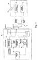
- FIG. 1 A simplified block diagram of an example of an oscilloscope system incorporating the present invention is shown in FIG. 1.
- An oscilloscope probe 10 is connected to channel B of an oscilloscope 12 or other electrical instrument.
- Probe 10 includes a probe body 20, a connector 22 for attachment to oscilloscope 12, and a cable 24 that interconnects probe body 20 and connector 22.
- a sensing element 30 and a probe memory 32 are mounted in probe body 20.
- Sensing element 30 may be a conductive probe tip that is connected, either directly or indirectly through interface circuitry, to oscilloscope 12.
- Probe memory 32 contains probe information that is electronically transferred to oscilloscope 12, as described in detail below.
- Probe 10 is configured for manual operation. As well known in the art, sensing element 30 is placed in electrical contact with a node of interest in an electrical circuit. A sensed signal is transmitted from sensing element 30 through cable 24 to oscilloscope 12 and is measured and/or displayed by oscilloscope 12. In some cases, the sensed signal may be preprocessed by circuitry within probe 10. Probe 10 is easily detachable from oscilloscope 12.
- oscilloscope 12 may include channel A and channel B, either or both of which may be connected to a probe. Each channel may include independent circuitry for processing sensed signals and forwarding the processed signals to a display unit or other indicating device. It will be understood that the oscilloscope may include a single channel or more than two channels within the scope of the invention. For simplicity, only those components that are relevant to the present invention are shown in FIG. 1.
- Oscilloscope 12 includes a parameter processor 40 for processing sensed signals, a display unit 42 for displaying parameter information and all other information associated with operation of oscilloscope 12, a calibration memory 46 for storing calibration information for one or more probes, a current probe storage unit 50 for storing identifying information for a probe currently connected to oscilloscope 12, and a clock 52 for providing timing signals to the circuitry in oscilloscope 12 and to probe memory 32 in probe 10.
- the parameter processor 40 may, for example, measure the sensed signal and/or may amplify the sensed signal to provide a waveform display.
- the calibration memory 46 and the current probe storage unit 50 may be implemented as RAM, hard disk or any other suitable storage device. Furthermore, these may be separate storage devices or different sections of one storage device.
- probe memory 32 contains probe information that uniquely identifies probe assembly 10.
- probe memory 32 may contain a model number and a serial number, and any other information or parameters required to uniquely identify probe 10.
- Probe memory 32 may contain additional information that may be useful in the operation of the oscilloscope system.
- the information contained in probe memory 32 may be electronically transmitted to oscilloscope 12 and may be used by oscilloscope 12 as described below.
- probe memory 32 is read by oscilloscope 12 following connection of probe 10 to oscilloscope 12.
- a serial data link is preferably utilized to provide a simple interface between probe 10 and oscilloscope 12.
- probe information that may be contained in probe memory 32. It will be understood that different probe information content and formats may be utilized within the scope of the invention.
- the probe information may further include a number of ASCII character strings.
- Each ASCII character string may end with one byte that is a stop byte of all zeros.
- the following are examples of ASCII character strings that may be contained in the probe memory 32.
- Strings 12-14 contain optional information of up to 30 ASCII characters each. Additional information listed above may be optional in certain applications. The volume of information is limited by the capacity of the probe memory 32.
- the probe model number and probe serial number may constitute a probe ID that uniquely identifies the probe 10 attached to channel B of oscilloscope 12.
- the probe information read from probe memory 32 may be stored in current probe storage unit 50 in oscilloscope 12.
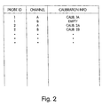
- the probe ID and channel are used to address calibration memory 46.
- calibration memory 46 may include calibration information for each probe that has been calibrated on each channel of the oscilloscope.
- different channels of the oscilloscope 12 may require different calibration data due to differences between channels.
- a particular probe may have different calibration information for channels A and B.
- calibration memory 46 An example of a suitable organization for calibration memory 46 is shown in FIG. 2. Calibration information is classified and addressed according to probe ID and channel. Thus, for example, when probe 2 is connected to channel B, calibration information 2B is accessed in calibration memory 46 and is supplied to parameter processor 40 for calibration of measurements by probe 2 on channel B. If probe 2 is connected to channel A, calibration information 2A is accessed in calibration memory 46. It may be observed that calibration memory 46 does not include calibration information for probe 1 connected to channel B, because probe 1 has not been calibrated on channel B.
- the calibration information contained in calibration memory 46 is acquired in a calibration procedure for each probe and channel combination.
- the calibration procedure is typically performed when a probe is first connected to a particular channel of the oscilloscope.
- a calibration procedure is performed and calibration information 1B is stored in calibration memory 46.
- the calibration information is retained in calibration memory 46 until it is deleted, for example, because the probe is no longer being used.
- the calibration information may include gain and offset correction factors.
- oscilloscope 12 has a large capacity storage, such as a hard disk, and may store a relatively large volume of calibration information.
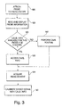
- a flow chart of an example of a process for utilization of the probe information contained in probe memory 32 is shown in FIG. 3.
- a probe is connected to oscilloscope 12 (FIG. 1) in step 100.
- the probe may be any model number and serial number that is compatible with the oscilloscope.
- the oscilloscope has no information as to the probe ID of the probe that is connected to the oscilloscope.
- oscilloscope 12 reads the probe information contained in probe memory 32 and stores the probe information in current probe storage unit 50.
- probe information window 110 may include the manufacturer, model number and serial number of the probe assembly, as well as any other parameters of interest.
- step 120 When it is determined in step 120 that calibration information is not available in calibration memory for the particular combination of probe assembly-and channel, a calibration routine is performed in step 140.
- the calibration routine is required when the particular probe has not previously been connected to the same channel of the oscilloscope.
- the calibration routine may prompt the user to perform any necessary calibration steps.
- the calibration information is stored in calibration memory 46 for future use and is supplied to parameter processor 40 for use in the current measurement session. The process then proceeds to step 124 for acquiring a measurement as described above.
- the probe memory 32 may utilize any suitable storage device.
- the storage device should be small in size for convenient packaging in probe 10 and should be low in cost.
- the storage device should be easily read by oscilloscope 12 with a minimum of additional circuitry and conductors in cable 24.
- the probe memory 32 preferably comprises a read-only memory, and more preferably comprises an electrically erasable and programmable read-only memory.
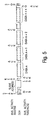
- probe memory 32 comprises a two-wire serial CMOS EEPROM, type AT24C02, manufactured and sold by Atmel. This device is organized into 256 8-bit bytes for a total of 2,048 bits. The device is supplied with a clock signal and has a bidirectional serial data line. The protocol for a sequential read is shown in FIG. 5.
- the oscilloscope supplies a slave address, and the memory device supplies a data word.
- the oscilloscope then provides an acknowledge, and the memory device supplies another data word. So long as the memory device receives acknowledge, it continues to increment the data word address and serially clock out sequential data words.
- probe information may vary widely in content and format within the scope of the invention.
- the storage device is required to store sufficient probe information to uniquely identify the probe, thereby permitting the oscilloscope to access stored calibration information.
Landscapes
- Physics & Mathematics (AREA)
- General Physics & Mathematics (AREA)
- Measuring Leads Or Probes (AREA)
- Tests Of Electronic Circuits (AREA)
Claims (8)
- Appareil comprenant :une sonde électrique (10) comprenant un corps de sonde (20), un élément de détection (30) pour détecter un paramètre électrique et un dispositif de mémorisation (32) contenant une information de sonde qui identifie de manière unique ladite sonde ; etun instrument électrique (12) pour traiter le paramètre électrique détecté par ledit élément de détection (30), ladite sonde (10) étant connectée de manière amovible à l'un d'une pluralité de canaux dudit instrument électrique (12), ledit instrument électrique comprenant un moyen pour lire ladite information de sonde dans le dispositif de mémorisation dans ladite sonde, caractérisé en ce que ledit instrument électrique comprend en outre des moyens (46) pour mémoriser une information d'étalonnage qui est associée à chacune des combinaisons de sondes électriques et de canaux d'instrument, et des moyens (40) pour accéder à ladite information d'étalonnage par l'utilisation de la combinaison de ladite information de sonde et dudit canal comme adresse et pour appliquer ladite information d'étalonnage au traitement du paramètre électrique.
- Appareil selon la revendication 1, dans lequel ledit dispositif de mémorisation comprend une mémoire morte.
- Appareil selon la revendication 1, dans lequel ladite sonde électrique comprend des moyens pour transmettre en série ladite information de sonde depuis ledit dispositif de mémorisation à l'instrument électrique.
- Appareil selon la revendication 1, dans lequel ledit dispositif de mémorisation comprend des moyens pour mémoriser un numéro de modèle et un numéro de série de la sonde.
- Appareil selon la revendication 1, dans lequel ledit instrument électrique comprend un oscilloscope.
- Appareil selon la revendication 1, dans lequel lesdits moyens de lecture comprennent des moyens pour lire automatiquement ladite information de sonde après la connexion de ladite sonde audit instrument électrique.
- Procédé d'étalonnage d'une sonde électrique (10) qui est connectée de manière amovible à l'un d'une pluralité de canaux d'un instrument électrique (12), comprenant les étapes consistant à :caractérisé en ce que le procédé comprend en outre les étapes consistant à :mémoriser dans la sonde une identité de sonde (32) qui identifie de manière unique la sonde ;transférer électroniquement (102) l'identité de sonde depuis la sonde à l'instrument électrique ;mémoriser dans une mémoire d'étalonnage (46) de l'instrument électrique une information d'étalonnage qui est associée à la combinaison de la sonde et d'un canal de l'instrument auquel la sonde a été connectée lorsqu'elle a été étalonnée ;accéder (122) à ladite information d'étalonnage depuis ladite mémoire d'étalonnage sur la base de ladite identité de sonde et dudit canal auquel ladite sonde est connectée ; etappliquer (130) ladite information d'étalonnage à laquelle on a accédé pour traiter les signaux mesurés avec la sonde.
- Procédé selon la revendication 7, dans lequel l'étape de transfert électronique de l'identité de sonde est effectuée automatiquement après la connexion de la sonde à l'instrument.
Applications Claiming Priority (2)
| Application Number | Priority Date | Filing Date | Title |
|---|---|---|---|
| US09/143,590 US6351112B1 (en) | 1998-08-31 | 1998-08-31 | Calibrating combinations of probes and channels in an oscilloscope |
| US143590 | 2002-05-08 |
Publications (2)
| Publication Number | Publication Date |
|---|---|
| EP0984287A1 EP0984287A1 (fr) | 2000-03-08 |
| EP0984287B1 true EP0984287B1 (fr) | 2003-08-13 |
Family
ID=22504729
Family Applications (1)
| Application Number | Title | Priority Date | Filing Date |
|---|---|---|---|
| EP99106530A Expired - Lifetime EP0984287B1 (fr) | 1998-08-31 | 1999-03-30 | Sonde et instrument électrique avec information de calibration mémorisée concernant des combinaisons sondes et canaux de l'instrument |
Country Status (4)
| Country | Link |
|---|---|
| US (1) | US6351112B1 (fr) |
| EP (1) | EP0984287B1 (fr) |
| JP (1) | JP2000074947A (fr) |
| DE (1) | DE69910319T2 (fr) |
Families Citing this family (27)
| Publication number | Priority date | Publication date | Assignee | Title |
|---|---|---|---|---|
| US6560554B1 (en) * | 1999-10-11 | 2003-05-06 | Tektronix, Inc. | Automatic testing |
| US6629048B1 (en) * | 2000-11-20 | 2003-09-30 | Tektronix, Inc. | Measurement test instrument and associated voltage management system for accessory device |
| US6725170B1 (en) * | 2000-11-22 | 2004-04-20 | Tektronix, Inc. | Smart probe apparatus and method for automatic self-adjustment of an oscilloscope's bandwidth |
| US6870359B1 (en) | 2001-12-14 | 2005-03-22 | Le Croy Corporation | Self-calibrating electrical test probe |
| US7180314B1 (en) | 2001-12-14 | 2007-02-20 | Lecroy Corporation | Self-calibrating electrical test probe calibratable while connected to an electrical component under test |
| US6919728B2 (en) * | 2002-02-27 | 2005-07-19 | Lecroy Corporation | Calibration cache and database |
| US6829547B2 (en) * | 2002-04-29 | 2004-12-07 | Tektronix, Inc. | Measurement test instrument and associated voltage management system for accessory device |
| US7109728B2 (en) * | 2003-02-25 | 2006-09-19 | Agilent Technologies, Inc. | Probe based information storage for probes used for opens detection in in-circuit testing |
| US20050185769A1 (en) * | 2004-02-25 | 2005-08-25 | Pickerd John J. | Calibration method and apparatus |
| DE102005007103A1 (de) * | 2005-02-16 | 2006-08-24 | Infineon Technologies Ag | Verfahren zum Testen einer zu testenden Schaltungseinheit mit Auskopplung von Verifikationssignalen und Testvorrichtung zur Durchführung des Verfahrens |
| US20070135983A1 (en) * | 2005-12-12 | 2007-06-14 | Automotive Systems Laboratory, Inc. | Initialization process for an occupant classification initialization |
| US7532492B2 (en) * | 2005-12-20 | 2009-05-12 | Tektronix, Inc. | Host controlled voltage input system for an accessory device |
| US7460983B2 (en) * | 2006-08-23 | 2008-12-02 | Tektronix, Inc. | Signal analysis system and calibration method |
| US7660685B2 (en) * | 2006-08-02 | 2010-02-09 | Lecroy Corporation | Virtual probing |
| US7414411B2 (en) * | 2006-08-23 | 2008-08-19 | Tektronix, Inc. | Signal analysis system and calibration method for multiple signal probes |
| US7408363B2 (en) * | 2006-08-23 | 2008-08-05 | Tektronix, Inc. | Signal analysis system and calibration method for processing acquires signal samples with an arbitrary load |
| US7405575B2 (en) * | 2006-08-23 | 2008-07-29 | Tektronix, Inc. | Signal analysis system and calibration method for measuring the impedance of a device under test |
| US12061218B2 (en) * | 2008-03-13 | 2024-08-13 | Ei Electronics Llc | System and method for multi-rate concurrent waveform capture and storage for power quality metering |
| US8446143B2 (en) * | 2008-06-27 | 2013-05-21 | National Instruments Corporation | Self-calibration circuit with gyrated output impedance |
| DE102011080481B4 (de) * | 2011-08-05 | 2016-04-07 | Rohde & Schwarz Gmbh & Co. Kg | System und Verfahren zur automatischen Kodierung einesTastkopfs |
| US9194888B2 (en) | 2012-10-11 | 2015-11-24 | Tektronix, Inc. | Automatic probe ground connection checking techniques |
| KR102015499B1 (ko) * | 2015-07-16 | 2019-08-28 | 엘에스산전 주식회사 | 오차보정시스템 |
| US10724878B2 (en) * | 2015-10-30 | 2020-07-28 | Fisher Controls International Llc | Methods and apparatus to correct remote sensor signals |
| EP3404426B1 (fr) * | 2017-05-18 | 2022-06-29 | Rohde & Schwarz GmbH & Co. KG | Oscilloscope, système d'essai et de mesure ainsi que procédé |
| US10768211B2 (en) | 2017-08-25 | 2020-09-08 | Oracle International Corporation | System and method for current sense resistor compensation |
| US11287445B2 (en) | 2018-10-29 | 2022-03-29 | Keysight Technologies, Inc. | Oscilloscope probe identification |
| CN113625032A (zh) * | 2021-07-01 | 2021-11-09 | 普源精电科技股份有限公司 | 一种探头测量系统和方法 |
Family Cites Families (15)
| Publication number | Priority date | Publication date | Assignee | Title |
|---|---|---|---|---|
| US3944921A (en) * | 1970-12-11 | 1976-03-16 | Canon Kabushiki Kaisha | Logic level test probe with grated oscillator |
| US3903471A (en) * | 1972-03-10 | 1975-09-02 | Canon Kk | Electronic circuit test equipment including a cathode ray tube detachably connected thereto using a plurality of information signals |
| US4042881A (en) * | 1975-06-23 | 1977-08-16 | Unitec, Inc. | Voltage measuring device having an amplifier in the probe |
| US4139817A (en) * | 1976-09-13 | 1979-02-13 | Tektronix, Inc. | Impedance-switching connector |
| US4403183A (en) * | 1981-04-10 | 1983-09-06 | Tektronix, Inc. | Active voltage probe |
| US4634971A (en) * | 1982-09-30 | 1987-01-06 | Ford Motor Company | Portable hand-held voltage sensor with manually adjustable reference voltage for comparison with sensed voltage |
| US4672306A (en) * | 1985-04-08 | 1987-06-09 | Tektronix, Inc. | Electronic probe having automatic readout of identification and status |
| US4758779A (en) * | 1986-04-07 | 1988-07-19 | Tektronix, Inc. | Probe body for an electrical measurement system |
| US4764879A (en) * | 1987-06-25 | 1988-08-16 | The Yellow Springs Instrument Company, Inc. | Fast/accurate calibration for a physical property sensor |
| US5162725A (en) * | 1989-08-21 | 1992-11-10 | Alnor Instrument Company | Modular metering instrument including multiple sensing probes |
| US5629617A (en) * | 1995-01-06 | 1997-05-13 | Hewlett-Packard Company | Multiplexing electronic test probe |
| US5691635A (en) | 1996-01-29 | 1997-11-25 | Fluke Corporation | Probe identification system for a measurement instrument |
| US6305963B1 (en) | 1996-08-16 | 2001-10-23 | Agilent Technologies, Inc. | Push-lock BNC connector |
| US5939875A (en) * | 1997-03-17 | 1999-08-17 | Hewlett-Packard Company | Universal probe interface |
| GB2323488B (en) | 1997-03-20 | 2000-12-27 | Sony Uk Ltd | Signal processors |
-
1998
- 1998-08-31 US US09/143,590 patent/US6351112B1/en not_active Expired - Fee Related
-
1999
- 1999-03-30 DE DE69910319T patent/DE69910319T2/de not_active Expired - Fee Related
- 1999-03-30 EP EP99106530A patent/EP0984287B1/fr not_active Expired - Lifetime
- 1999-08-31 JP JP11244302A patent/JP2000074947A/ja active Pending
Also Published As
| Publication number | Publication date |
|---|---|
| JP2000074947A (ja) | 2000-03-14 |
| DE69910319T2 (de) | 2004-06-09 |
| US6351112B1 (en) | 2002-02-26 |
| EP0984287A1 (fr) | 2000-03-08 |
| DE69910319D1 (de) | 2003-09-18 |
Similar Documents
| Publication | Publication Date | Title |
|---|---|---|
| EP0984287B1 (fr) | Sonde et instrument électrique avec information de calibration mémorisée concernant des combinaisons sondes et canaux de l'instrument | |
| US4672306A (en) | Electronic probe having automatic readout of identification and status | |
| KR101231750B1 (ko) | 호스트에 의해 제어되는 부속 기기의 전압 관리 시스템 | |
| US5790432A (en) | Universal measuring instrument with signal processing algorithm encapsulated into interchangeable intelligent detectors | |
| JP4942940B2 (ja) | 校正方法及び測定機器 | |
| US6564278B1 (en) | System and method for obtaining board address information | |
| JPH05503583A (ja) | 自動車試験のための自動化ブレークアウトボックス | |
| US5939875A (en) | Universal probe interface | |
| JP2000074947A5 (fr) | ||
| DE10350859A1 (de) | Sondenbasierten Informationsspeicher für Sonden, die zur Leerlauferfassung bei einem schaltungsinternen Testen verwendet werden | |
| US20220205851A1 (en) | Calibration System for Fiber Optic Temperature Probe | |
| US5248933A (en) | Calibration | |
| CN111800191A (zh) | 光模块调测装置、调测方法及电子设备 | |
| CN112684234B (zh) | 示波器的探头识别方法和示波器 | |
| US6385550B1 (en) | Apparatus and method for providing forward and backward compatibility between a host instrument and an accessory | |
| US7016792B2 (en) | Transducer comprising a connected data memory | |
| EP0213407A2 (fr) | Méthode et dispositif pour la mesure de température corporelle avec plusieurs types de capteurs | |
| CN103018569B (zh) | 一种线材阻抗测试仪及测试方法 | |
| US7308519B2 (en) | Communications bus management circuit | |
| US5475384A (en) | Remote addressable transducer provided with automatic calibration and digital compensation | |
| JP5125989B2 (ja) | センサ本体および接続機器 | |
| JP2005517949A (ja) | 物理量を測定するためのユニバーサル入力式のデータ収集モジュール | |
| WO2022104748A1 (fr) | Procédé d'étalonnage d'appareil de surveillance de type implanté, ensemble capteur et système de surveillance de glucose sanguin | |
| CN219842090U (zh) | 一种短型热电偶的宽范围校准装置 | |
| JP2000235048A (ja) | 測定用プローブ |
Legal Events
| Date | Code | Title | Description |
|---|---|---|---|
| PUAI | Public reference made under article 153(3) epc to a published international application that has entered the european phase |
Free format text: ORIGINAL CODE: 0009012 |
|
| AK | Designated contracting states |
Kind code of ref document: A1 Designated state(s): DE FR GB |
|
| AX | Request for extension of the european patent |
Free format text: AL;LT;LV;MK;RO;SI |
|
| 17P | Request for examination filed |
Effective date: 20000322 |
|
| AKX | Designation fees paid |
Free format text: DE FR GB |
|
| RAP1 | Party data changed (applicant data changed or rights of an application transferred) |
Owner name: AGILENT TECHNOLOGIES, INC. |
|
| RAP1 | Party data changed (applicant data changed or rights of an application transferred) |
Owner name: AGILENT TECHNOLOGIES INC. |
|
| RAP1 | Party data changed (applicant data changed or rights of an application transferred) |
Owner name: AGILENT TECHNOLOGIES INC. A DELAWARE CORPORATION |
|
| RAP1 | Party data changed (applicant data changed or rights of an application transferred) |
Owner name: AGILENT TECHNOLOGIES, INC. (A DELAWARE CORPORATION |
|
| 17Q | First examination report despatched |
Effective date: 20020708 |
|
| RTI1 | Title (correction) |
Free format text: PROBE AND ELECTRICAL INSTRUMENT HAVING STORED CALIBRATION INFORMATION ABOUT COMBINATIONS OF PROBES AND INSTRUMENT CHANNELS |
|
| GRAH | Despatch of communication of intention to grant a patent |
Free format text: ORIGINAL CODE: EPIDOS IGRA |
|
| RTI1 | Title (correction) |
Free format text: PROBE AND ELECTRICAL INSTRUMENT HAVING STORED CALIBRATION INFORMATION ABOUT COMBINATIONS OF PROBES AND INSTRUMENT CHANNEL |
|
| GRAA | (expected) grant |
Free format text: ORIGINAL CODE: 0009210 |
|
| GRAS | Grant fee paid |
Free format text: ORIGINAL CODE: EPIDOSNIGR3 |
|
| AK | Designated contracting states |
Designated state(s): DE FR GB |
|
| REG | Reference to a national code |
Ref country code: GB Ref legal event code: FG4D |
|
| REF | Corresponds to: |
Ref document number: 69910319 Country of ref document: DE Date of ref document: 20030918 Kind code of ref document: P |
|
| PG25 | Lapsed in a contracting state [announced via postgrant information from national office to epo] |
Ref country code: GB Free format text: LAPSE BECAUSE OF NON-PAYMENT OF DUE FEES Effective date: 20040330 |
|
| ET | Fr: translation filed | ||
| PLBE | No opposition filed within time limit |
Free format text: ORIGINAL CODE: 0009261 |
|
| STAA | Information on the status of an ep patent application or granted ep patent |
Free format text: STATUS: NO OPPOSITION FILED WITHIN TIME LIMIT |
|
| 26N | No opposition filed |
Effective date: 20040514 |
|
| GBPC | Gb: european patent ceased through non-payment of renewal fee |
Effective date: 20040330 |
|
| PG25 | Lapsed in a contracting state [announced via postgrant information from national office to epo] |
Ref country code: FR Free format text: LAPSE BECAUSE OF NON-PAYMENT OF DUE FEES Effective date: 20041130 |
|
| REG | Reference to a national code |
Ref country code: FR Ref legal event code: ST |
|
| PGFP | Annual fee paid to national office [announced via postgrant information from national office to epo] |
Ref country code: DE Payment date: 20070430 Year of fee payment: 9 |
|
| PG25 | Lapsed in a contracting state [announced via postgrant information from national office to epo] |
Ref country code: DE Free format text: LAPSE BECAUSE OF NON-PAYMENT OF DUE FEES Effective date: 20081001 |