EP0984242A2 - Versperrbare Halterung für Schusswaffen - Google Patents
Versperrbare Halterung für Schusswaffen Download PDFInfo
- Publication number
- EP0984242A2 EP0984242A2 EP99890228A EP99890228A EP0984242A2 EP 0984242 A2 EP0984242 A2 EP 0984242A2 EP 99890228 A EP99890228 A EP 99890228A EP 99890228 A EP99890228 A EP 99890228A EP 0984242 A2 EP0984242 A2 EP 0984242A2
- Authority
- EP
- European Patent Office
- Prior art keywords
- locking
- sleeve
- balls
- weapon
- extension
- Prior art date
- Legal status (The legal status is an assumption and is not a legal conclusion. Google has not performed a legal analysis and makes no representation as to the accuracy of the status listed.)
- Withdrawn
Links
Images
Classifications
-
- A—HUMAN NECESSITIES
- A47—FURNITURE; DOMESTIC ARTICLES OR APPLIANCES; COFFEE MILLS; SPICE MILLS; SUCTION CLEANERS IN GENERAL
- A47B—TABLES; DESKS; OFFICE FURNITURE; CABINETS; DRAWERS; GENERAL DETAILS OF FURNITURE
- A47B81/00—Cabinets or racks specially adapted for other particular purposes, e.g. for storing guns or skis
- A47B81/005—Devices for storing or displaying rifles, guns, pistols or elongated objects such as fishing rods storing fishing rods
-
- B—PERFORMING OPERATIONS; TRANSPORTING
- B60—VEHICLES IN GENERAL
- B60R—VEHICLES, VEHICLE FITTINGS, OR VEHICLE PARTS, NOT OTHERWISE PROVIDED FOR
- B60R7/00—Stowing or holding appliances inside vehicle primarily intended for personal property smaller than suit-cases, e.g. travelling articles, or maps
- B60R7/08—Disposition of racks, clips, holders, containers or the like for supporting specific articles
- B60R7/14—Disposition of racks, clips, holders, containers or the like for supporting specific articles for supporting weapons
-
- E—FIXED CONSTRUCTIONS
- E05—LOCKS; KEYS; WINDOW OR DOOR FITTINGS; SAFES
- E05B—LOCKS; ACCESSORIES THEREFOR; HANDCUFFS
- E05B63/00—Locks or fastenings with special structural characteristics
- E05B63/12—Locks or fastenings with special structural characteristics with means carried by the bolt for interlocking with the keeper
- E05B63/121—Locks or fastenings with special structural characteristics with means carried by the bolt for interlocking with the keeper using balls or the like cooperating with notches
-
- F—MECHANICAL ENGINEERING; LIGHTING; HEATING; WEAPONS; BLASTING
- F41—WEAPONS
- F41A—FUNCTIONAL FEATURES OR DETAILS COMMON TO BOTH SMALLARMS AND ORDNANCE, e.g. CANNONS; MOUNTINGS FOR SMALLARMS OR ORDNANCE
- F41A23/00—Gun mountings, e.g. on vehicles; Disposition of guns on vehicles
- F41A23/02—Mountings without wheels
- F41A23/18—Rests for supporting smallarms in non-shooting position
Definitions
- the invention relates to a lockable holder for Firearms with a connector on the weapon and one Coupling piece, which is arranged stationary. To the It is to secure access to firearms from unauthorized persons It is advisable to keep the firearms locked. Except of steel cabinets for hunting weapons are also lockable Brackets known using brackets or rods prevent removal. In emergency vehicles, for example firearms should be readily available to the police. On the other hand, these firearms must be used against an unauthorized person Removal should be assured, considering the officials a radio patrol for the time being for exploration leave the vehicle without taking the assault rifle with them. It must be avoided that third parties now of these weapons in the parked vehicle.
- the connector as Sleeve formed and on the weapon, especially on or in Rifle butt or stock essentially unsolvable is attached that the coupling piece carries a shoulder, onto which the sleeve including the weapon can be attached and that on the part of the projection protruding into the sleeve a lock is provided which is form-fitting on the sleeve attacks, the locking by a Lock cylinder in the coupling piece, can be actuated.
- the sleeve can be screwed into a bore in the piston.
- the hole the sleeve itself can be cylindrical. Then it has Approach of e.g. attached to the cardan tunnel of the vehicle Coupling piece also cylindrical.
- the sleeve can also be designed as a plug that has a slot that then on the approach of the coupling piece with a rectangular cross section is postponed.
- the lock can lock in place and only by means of a key can be opened or it can be the weapon inserted and then locked using the key, the key to unlock again when removing necessary is.
- a special embodiment of the invention is characterized by the fact that locking bodies, in particular balls, preferably provided diametrically in the approach are radial beyond the scope of the approach Direction engaging in a recess in the sleeve bore or an edge of the sleeve can be pushed out behind, that the locking bodies, especially balls, inside the Approach is opposite a hole in which the locking body or retract the balls in a retractable manner in the hole a gate valve is provided, preferably conical trained end faces on the locking bodies, in particular Balls for their radial positioning and that the locking slide with its foot end at one Shoulder of the lock cylinder housing is in the locked position and a recess for immersion and retreat of the locking slide and thus the locking body, in particular Balls, in the open position in the lock cylinder housing is provided.
- the particularly designed as balls Locking bodies can be moved radially in the cross bores of the attachment, but ensuring that they are out of their Holes cannot fall out.
- This can be done either a spring washer with coaxial holes to the holes for the balls e.g. be provided in a groove on the outside of the base, the coaxial holes being slightly smaller in diameter have than the bore diameter in the approach.
- the balls are pushed radially outwards by the locking slide and engage in an annular groove of the sleeve or engage behind it simply the sleeve at its inner end.
- the Gate valve its direction of displacement in the hollow approach is perpendicular to the direction of movement of the balls, backs away or under the pressure of the balls due to its conical Tip is pushed back, then the balls completely immerse in the approach and thereby come with the Sleeve out of engagement in the weapon.
- the gate valve supports on the foot side of a shoulder of the lock cylinder housing or an extension of the same, if the Lock cylinder is in the locked position. Will the Lock cylinder unlocked, then it turns and the The recess is aligned with the locking slide and enables its retreat.
- Slidable traps can be provided with chamfers.
- the sleeve runs onto the sloping inlet on, push this down until the traps are behind engage a locking surface in the sleeve.
- the gate valve prevents the wedge-shaped traps from being pushed back Blocking body. Is the gate valve using the Retracted lock cylinder, then he takes a ring, which runs onto the sloping inlet of the traps and this in pushes the approach in.
- the Balls are resiliently supported in the radial direction and in the Locking position of the locking slide the travel against the interior the hole is blocked.
- the resilient bearing can by a reached open spring ring provided inside the bore e.g. in an annular groove of the bore of the neck lies and the balls radially resilient to the outside presses. Openings with something smaller can be made in the spring ring Diameter as the ball diameter for storing the balls be provided.
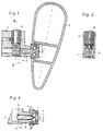
- FIG. 1 shows a section through a locked bracket with a coupling piece and a connector in the barrel of a rifle
- 2 shows a section along the line II-II in FIG. 1st 3 shows a detail from FIG. 1, but in the unlocked state, so that the weapon can be removed.
- the Sleeve 1 is a connector designed as a sleeve 1 screwed into the barrel 2 of a rifle.
- the Sleeve 1 has a recess, here a bore 3, which carries an annular groove 4 inside.
- a coupling piece 5 is with a solid part, for example of an emergency vehicle firmly connected.
- the coupling piece 5 comprises an extension 6, the cross-sectional shape of which the recess (bore 3) in the sleeve 1 matches - whose outer diameter here is the inner diameter of the Sleeve 1 corresponds.
- the rifle butt 2 or the rifle can therefore be placed on the coupling piece.
- the barrel is initially secured by a rigidly mounted on the vehicle at a distance from the coupling piece 5 Ring or a cuff or in a cap (not shown) and then the above connection made with the approach 6 of the coupling piece 5.
- the locking cylinder 12 by means of a flat key is rotated - e.g. 90 ° - then the shoulder turns as Support for the locking slide 10 away and a recess 13 lies opposite the foot end of the locking slide 10.
- the gate valve 10 can dip into this recess 13 if he is pushed back by the balls 9 over the ball tip. This situation is shown in Fig. 3.
- the balls 9 themselves can recede into the interior of the neck 6, whereby the locking is released.
- the recess 13 is as tangential groove in the cylindrical housing 11 of the locking cylinder 12 or formed in its cylindrical extension; the recess 13 is grinding in the full cross section of the lock cylinder housing 11 over. So will that Key inserted in the locking cylinder 12 and from Fig. 3 starting from a 90 ° rotation, then pushes if necessary also curved guide surface at the bottom of the groove Gate valve 10 against the balls 9, which then radially into the 1 position.
- Can between the lock cylinder and the locking slide also a cam control or eccentric control, also in Form of a positive control provided by the lock cylinder his.
Landscapes
- Engineering & Computer Science (AREA)
- General Engineering & Computer Science (AREA)
- Mechanical Engineering (AREA)
- Structural Engineering (AREA)
- Quick-Acting Or Multi-Walled Pipe Joints (AREA)
- Toys (AREA)
Abstract
Description
Claims (6)
- Versperrbare Halterung für Schusswaffen mit einem Verbindungsstück an der Waffe und einem Kupplungsstück, welches ortsfest angeordnet ist, dadurch gekennzeichnet, dass das Verbindungsstück als Hülse (1) ausgebildet und an der Waffe, insbesondere am bzw. im Kolben (2) oder Schaft eines Gewehres im Wesentlichen unlösbar befestigt ist, dass das Kupplungsstück (5) einen Ansatz (6) trägt, auf den die Hülse (1) einschließlich der Waffe aufsteckbar ist und dass an dem in die Hülse (1) hineinragenden Teil des Ansatzes (6) eine Verriegelung vorgesehen ist, die an der Hülse (1) formschlüssig angreift, wobei die Verriegelung durch einen Schließzylinder (12) im Kupplungsstück (5), betätigbar ist.
- Versperrbare Halterung nach Anspruch 1, dadurch gekennzeichnet, dass als Verrieglung Sperrkörper, insbesondere Kugeln (9), vorzugsweise diametral im Ansatz (6) vorgesehen sind, die über den Umfang des Ansatzes (6) hinaus in radialer Richtung in eine Ausnehmung (4) der Hülsenbohrung (3) eingreifend oder eine Kante der Hülse (1) hintergreifend ausschiebbar sind, dass den Sperrkörpern, insbesondere Kugeln (9), im Inneren des Ansatzes (6) eine Bohrung (7) gegenüberliegt, in die die Sperrkörper bzw. Kugeln (9) zurückweichend eintauchen, dass in der Bohrung (7) ein Sperrschieber (10) vorgesehen ist, dessen vorzugsweise kegelförmig ausgebildete Stirnflächen an den Sperrkörpern, insbesondere Kugeln (9), zu deren radialen Positionierung anliegt und dass der Sperrschieber (10) mit seinem fußseitigen Ende an einer Schulter des Schließzylindergehäuses (11) in der Sperrstellung anliegt und eine Ausnehmung (13) zum Eintauchen und Zurückweichen des Sperrschiebers (10) und damit der Sperrkörper, insbesondere Kugeln (9), in der Offenstellung in dem Schließzylindergehäuse (11) vorgesehen ist.
- Versperrbare Halterung nach Anspruch 2, dadurch gekennzeichnet, dass die Sperrkörper, vorzugsweise die Kugeln (9), in radialer Richtung federnd gelagert sind und in der Sperrstellung der Sperrschieber (10) den Federweg gegen das Innere der Bohrung (7) blockiert.
- Versperrbare Halterung nach einen der Ansprüche 1 bis 3, dadurch gekennzeichnet, dass als Sperrkörper fallenartige Keilstücke in radialer Richtung zum Ansatz (6) in diesem federend vorgesehen sind, die in Schlitze des Ansatzes (6) gegen Federkraft eintauchen und durch den Sperrschieber (10) einziehbar sind.
- Versperrbare Halterung nach Anspruch 4, dadurch gekennzeichnet, dass die fallenartigen Keilstücke eine Einlaufschräge und eine daran anschließende Stirnfläche aufweisen und beim Aufsetzen der Waffe die Einlaufschrägen auf die Hülse (1) auflaufen und die Stirnflächen hinter einer Anlagefläche der Hülse (1) einrasten.
- Versperrbare Halterung nach Anspruch 1, dadurch gekennzeichnet, dass der Ansatz selbst als Rohrstück in axialer Richtung mehrfach geschlitzt ausgeführt ist und die durch die Schlitze gebildeten federnden Finger stirnseitig mit Einlaufschrägen versehene Nocken tragen, die am Ende der Finger radial nach außen gerichtet sind und dass ein durch einen Schließzylinder (12) gesteuerter Sperrschieber (10) die Finger in der Sperrstellung untergreift und ein Zurückweichen aus einer Verbindung, insbesondere Formschlussverbindung, mit der Hülse (1) unterbindet bzw. in der Freigabestellung den Raum zum Zurückfedern der Finger freigibt.
Applications Claiming Priority (2)
| Application Number | Priority Date | Filing Date | Title |
|---|---|---|---|
| AT57698U AT2953U1 (de) | 1998-09-02 | 1998-09-02 | Versperrbare halterung für schusswaffen |
| AT57698U | 1998-09-02 |
Publications (2)
| Publication Number | Publication Date |
|---|---|
| EP0984242A2 true EP0984242A2 (de) | 2000-03-08 |
| EP0984242A3 EP0984242A3 (de) | 2001-05-09 |
Family
ID=3494244
Family Applications (1)
| Application Number | Title | Priority Date | Filing Date |
|---|---|---|---|
| EP99890228A Withdrawn EP0984242A3 (de) | 1998-09-02 | 1999-07-06 | Versperrbare Halterung für Schusswaffen |
Country Status (2)
| Country | Link |
|---|---|
| EP (1) | EP0984242A3 (de) |
| AT (1) | AT2953U1 (de) |
Cited By (1)
| Publication number | Priority date | Publication date | Assignee | Title |
|---|---|---|---|---|
| DE102010018136A1 (de) | 2010-04-24 | 2011-10-27 | Rheinmetall Landsysteme Gmbh | Transporttasche insbesondere für den Fahrzeugeinbau |
Family Cites Families (2)
| Publication number | Priority date | Publication date | Assignee | Title |
|---|---|---|---|---|
| US4256245A (en) * | 1979-10-26 | 1981-03-17 | Serres Paul J | Gun-mounting apparatus |
| US5129563A (en) * | 1990-07-27 | 1992-07-14 | John Dillon | Assembly for mounting a shotgun to a car seat |
-
1998
- 1998-09-02 AT AT57698U patent/AT2953U1/de not_active IP Right Cessation
-
1999
- 1999-07-06 EP EP99890228A patent/EP0984242A3/de not_active Withdrawn
Non-Patent Citations (1)
| Title |
|---|
| None |
Cited By (3)
| Publication number | Priority date | Publication date | Assignee | Title |
|---|---|---|---|---|
| DE102010018136A1 (de) | 2010-04-24 | 2011-10-27 | Rheinmetall Landsysteme Gmbh | Transporttasche insbesondere für den Fahrzeugeinbau |
| WO2011131351A1 (de) | 2010-04-24 | 2011-10-27 | Rheinmetall Landsysteme Gmbh | Transporttasche insbesondere für den fahrzeugeinbau |
| EP2564145B1 (de) | 2010-04-24 | 2020-01-08 | Rheinmetall Landsysteme GmbH | Transporttasche insbesondere für den fahrzeugeinbau |
Also Published As
| Publication number | Publication date |
|---|---|
| AT2953U1 (de) | 1999-07-26 |
| EP0984242A3 (de) | 2001-05-09 |
Similar Documents
| Publication | Publication Date | Title |
|---|---|---|
| DE68918093T2 (de) | Sicherheitsverriegelung für feuerwaffen. | |
| DE69711299T2 (de) | Karabinerhaken mit Verriegelungsvorrichtung | |
| DE102015102073B3 (de) | Zylinder-Verschluss-Vorrichtung einer Repetier-Waffe | |
| DE102004023555B4 (de) | Repetierwaffe | |
| WO2009103414A1 (de) | Sicherheitsvorreiber | |
| DE2059380B2 (de) | Vorrichtung zum Kuppeln eines Verschlussträgers mit einem Verschlusskörper einer selbsttätigen Feuerwaffe | |
| EP0869326B1 (de) | Verriegelte Handfeuerwaffe | |
| DE1225517B (de) | Schulterstuetze fuer Handfeuerwaffen | |
| DE1453934A1 (de) | Selbsttaetige Feuerwaffe | |
| DE2227780C3 (de) | Zylinderverschluß für Handfeuerwaffen | |
| DE102022102808A1 (de) | Kammer einer Handfeuerwaffe | |
| DE20212656U1 (de) | Haltebolzenanordnung | |
| EP0984242A2 (de) | Versperrbare Halterung für Schusswaffen | |
| DE9007529U1 (de) | Multikaliber-Schußwaffe | |
| EP4438990B1 (de) | Verschlusskopf eines gewehrverschlusses und gewehrverschluss mit einem derartigen verschlusskopf | |
| DE1913412B2 (de) | Lenk- und zuendschloss fuer fahrzeuge | |
| DE3406757A1 (de) | Luftdruckwaffe | |
| EP4438989B1 (de) | Gewehrverschluss und gewehr mit einem derartigen gewehrverschluss | |
| DE2605587C2 (de) | Kraftfahrzeug-Lenkschloß | |
| DE1478997A1 (de) | Repetierpistole zum Setzen von Schiessbolzen | |
| EP3690381B1 (de) | Schusswaffe mit repetierfunktion | |
| EP0267407B1 (de) | Sicherungseinrichtung für einen Zünder eines Gefechtskopfes | |
| DE2814223A1 (de) | Kraftfahrzeug-lenkschloss | |
| EP1826340A1 (de) | Zylinderschloss mit Sperrscheiben | |
| DE102009051594A1 (de) | Haken, insbesondere für Sicherheitseinrichtungen |
Legal Events
| Date | Code | Title | Description |
|---|---|---|---|
| PUAI | Public reference made under article 153(3) epc to a published international application that has entered the european phase |
Free format text: ORIGINAL CODE: 0009012 |
|
| AK | Designated contracting states |
Kind code of ref document: A2 Designated state(s): AT BE CH CY DE DK ES FI FR GB GR IE IT LI LU MC NL PT SE |
|
| AX | Request for extension of the european patent |
Free format text: AL;LT;LV;MK;RO;SI |
|
| PUAL | Search report despatched |
Free format text: ORIGINAL CODE: 0009013 |
|
| AK | Designated contracting states |
Kind code of ref document: A3 Designated state(s): AT BE CH CY DE DK ES FI FR GB GR IE IT LI LU MC NL PT SE |
|
| AX | Request for extension of the european patent |
Free format text: AL;LT;LV;MK;RO;SI |
|
| AKX | Designation fees paid | ||
| REG | Reference to a national code |
Ref country code: DE Ref legal event code: 8566 |
|
| STAA | Information on the status of an ep patent application or granted ep patent |
Free format text: STATUS: THE APPLICATION IS DEEMED TO BE WITHDRAWN |
|
| 18D | Application deemed to be withdrawn |
Effective date: 20011110 |