EP0983812B1 - Verfahren zur Applikation eines Trenn- oder Schmierstoffs - Google Patents
Verfahren zur Applikation eines Trenn- oder Schmierstoffs Download PDFInfo
- Publication number
- EP0983812B1 EP0983812B1 EP99109269A EP99109269A EP0983812B1 EP 0983812 B1 EP0983812 B1 EP 0983812B1 EP 99109269 A EP99109269 A EP 99109269A EP 99109269 A EP99109269 A EP 99109269A EP 0983812 B1 EP0983812 B1 EP 0983812B1
- Authority
- EP
- European Patent Office
- Prior art keywords
- casting
- die
- lubricant
- release agent
- pressure
- Prior art date
- Legal status (The legal status is an assumption and is not a legal conclusion. Google has not performed a legal analysis and makes no representation as to the accuracy of the status listed.)
- Expired - Lifetime
Links
- 238000000034 method Methods 0.000 title claims abstract description 30
- 239000000314 lubricant Substances 0.000 title claims description 30
- 238000005266 casting Methods 0.000 claims abstract description 96
- 230000005494 condensation Effects 0.000 claims abstract description 15
- 238000009833 condensation Methods 0.000 claims abstract description 14
- 238000004512 die casting Methods 0.000 claims description 62
- 239000000126 substance Substances 0.000 claims description 20
- 239000012159 carrier gas Substances 0.000 claims description 12
- 229910001338 liquidmetal Inorganic materials 0.000 claims description 11
- 239000000203 mixture Substances 0.000 claims description 7
- 238000009834 vaporization Methods 0.000 claims description 3
- 150000001875 compounds Chemical class 0.000 claims 12
- 238000001704 evaporation Methods 0.000 abstract description 19
- 230000008020 evaporation Effects 0.000 abstract description 17
- 239000000463 material Substances 0.000 abstract description 9
- 238000000926 separation method Methods 0.000 abstract description 7
- 238000009434 installation Methods 0.000 abstract 1
- 238000004519 manufacturing process Methods 0.000 abstract 1
- 239000003795 chemical substances by application Substances 0.000 description 83
- 229910052751 metal Inorganic materials 0.000 description 15
- 239000002184 metal Substances 0.000 description 15
- 239000007789 gas Substances 0.000 description 9
- 239000007788 liquid Substances 0.000 description 9
- 239000007787 solid Substances 0.000 description 9
- 239000001993 wax Substances 0.000 description 8
- 239000008188 pellet Substances 0.000 description 7
- 150000002148 esters Chemical class 0.000 description 4
- RTZKZFJDLAIYFH-UHFFFAOYSA-N Diethyl ether Chemical compound CCOCC RTZKZFJDLAIYFH-UHFFFAOYSA-N 0.000 description 2
- NINIDFKCEFEMDL-UHFFFAOYSA-N Sulfur Chemical compound [S] NINIDFKCEFEMDL-UHFFFAOYSA-N 0.000 description 2
- 238000010586 diagram Methods 0.000 description 2
- 230000000977 initiatory effect Effects 0.000 description 2
- PNDPGZBMCMUPRI-UHFFFAOYSA-N iodine Chemical compound II PNDPGZBMCMUPRI-UHFFFAOYSA-N 0.000 description 2
- 238000005461 lubrication Methods 0.000 description 2
- 230000008016 vaporization Effects 0.000 description 2
- 229910052582 BN Inorganic materials 0.000 description 1
- PZNSFCLAULLKQX-UHFFFAOYSA-N Boron nitride Chemical compound N#B PZNSFCLAULLKQX-UHFFFAOYSA-N 0.000 description 1
- OKTJSMMVPCPJKN-UHFFFAOYSA-N Carbon Chemical compound [C] OKTJSMMVPCPJKN-UHFFFAOYSA-N 0.000 description 1
- RYGMFSIKBFXOCR-UHFFFAOYSA-N Copper Chemical compound [Cu] RYGMFSIKBFXOCR-UHFFFAOYSA-N 0.000 description 1
- 239000000443 aerosol Substances 0.000 description 1
- 229910045601 alloy Inorganic materials 0.000 description 1
- 239000000956 alloy Substances 0.000 description 1
- 150000001408 amides Chemical class 0.000 description 1
- 239000010692 aromatic oil Substances 0.000 description 1
- KGBXLFKZBHKPEV-UHFFFAOYSA-N boric acid Chemical class OB(O)O KGBXLFKZBHKPEV-UHFFFAOYSA-N 0.000 description 1
- 150000001735 carboxylic acids Chemical class 0.000 description 1
- QCCDYNYSHILRDG-UHFFFAOYSA-K cerium(3+);trifluoride Chemical compound [F-].[F-].[F-].[Ce+3] QCCDYNYSHILRDG-UHFFFAOYSA-K 0.000 description 1
- 238000004891 communication Methods 0.000 description 1
- 229910052802 copper Inorganic materials 0.000 description 1
- 239000010949 copper Substances 0.000 description 1
- 230000000694 effects Effects 0.000 description 1
- 238000005485 electric heating Methods 0.000 description 1
- 150000002170 ethers Chemical class 0.000 description 1
- 239000000945 filler Substances 0.000 description 1
- 239000010439 graphite Substances 0.000 description 1
- 229910002804 graphite Inorganic materials 0.000 description 1
- 230000005484 gravity Effects 0.000 description 1
- 238000010438 heat treatment Methods 0.000 description 1
- 239000011810 insulating material Substances 0.000 description 1
- 229910052740 iodine Inorganic materials 0.000 description 1
- 230000008018 melting Effects 0.000 description 1
- 238000002844 melting Methods 0.000 description 1
- 239000002480 mineral oil Substances 0.000 description 1
- 235000010446 mineral oil Nutrition 0.000 description 1
- 238000002156 mixing Methods 0.000 description 1
- 239000006082 mold release agent Substances 0.000 description 1
- CWQXQMHSOZUFJS-UHFFFAOYSA-N molybdenum disulfide Chemical compound S=[Mo]=S CWQXQMHSOZUFJS-UHFFFAOYSA-N 0.000 description 1
- 229910052982 molybdenum disulfide Inorganic materials 0.000 description 1
- 239000003921 oil Substances 0.000 description 1
- 230000035515 penetration Effects 0.000 description 1
- 150000003014 phosphoric acid esters Chemical class 0.000 description 1
- 239000004033 plastic Substances 0.000 description 1
- 229920000642 polymer Polymers 0.000 description 1
- 229920001296 polysiloxane Polymers 0.000 description 1
- 239000002244 precipitate Substances 0.000 description 1
- 239000000047 product Substances 0.000 description 1
- 230000000284 resting effect Effects 0.000 description 1
- 239000000344 soap Substances 0.000 description 1
- 238000003892 spreading Methods 0.000 description 1
- 239000011593 sulfur Substances 0.000 description 1
- 229910052717 sulfur Inorganic materials 0.000 description 1
- 230000009974 thixotropic effect Effects 0.000 description 1
- 230000007704 transition Effects 0.000 description 1
- 238000004148 unit process Methods 0.000 description 1
- 238000003466 welding Methods 0.000 description 1
Images


Classifications
-
- B—PERFORMING OPERATIONS; TRANSPORTING
- B22—CASTING; POWDER METALLURGY
- B22D—CASTING OF METALS; CASTING OF OTHER SUBSTANCES BY THE SAME PROCESSES OR DEVICES
- B22D17/00—Pressure die casting or injection die casting, i.e. casting in which the metal is forced into a mould under high pressure
- B22D17/20—Accessories: Details
- B22D17/2007—Methods or apparatus for cleaning or lubricating moulds
-
- B—PERFORMING OPERATIONS; TRANSPORTING
- B22—CASTING; POWDER METALLURGY
- B22C—FOUNDRY MOULDING
- B22C23/00—Tools; Devices not mentioned before for moulding
- B22C23/02—Devices for coating moulds or cores
-
- B—PERFORMING OPERATIONS; TRANSPORTING
- B22—CASTING; POWDER METALLURGY
- B22C—FOUNDRY MOULDING
- B22C3/00—Selection of compositions for coating the surfaces of moulds, cores, or patterns
-
- B—PERFORMING OPERATIONS; TRANSPORTING
- B22—CASTING; POWDER METALLURGY
- B22C—FOUNDRY MOULDING
- B22C9/00—Moulds or cores; Moulding processes
- B22C9/12—Treating moulds or cores, e.g. drying, hardening
Definitions
- the invention relates to a method for applying a separation or Lubricant on the surface of a casting piston and / or the inner wall a casting chamber, a pouring channel and / or a mold cavity Die casting machine.
- the press system of a casting machine regularly includes a die casting unit with a casting mold, a casting piston and a casting chamber.
- the casting plunger and casting chamber system elements are usually combined with one Lubricant or release agent treated by a release film around the casting piston forms, reduces the friction between the piston and chamber and thus their Extended lifespan.
- the mold cavity of a die casting unit is regularly covered with a mold release agent (Die casting release agent) treated, the one in the first place Welding or sticking the liquid cast metal to the mold wall prevent, but also to improve the metal flow as well as for the lubrication of the ejector pins and the movable molded parts should serve.
- a mold release agent Die casting release agent
- a release agent or lubricant is used (hereinafter also briefly Called “release agent”), which in gaseous form when entering the die casting unit Condition is present and then within the die casting unit on the surfaces to be treated, the temperature of which is lower than the evaporation temperature of the release agent or lubricant.
- release agent or lubricant
- the selection of the Release agent or lubricant (or its components) depends on the previously known temperatures of the surfaces to be treated within the Casting unit off before filling the mold with casting metal. These temperatures again vary depending on the casting weight / shot weight from which Wall thickness of the castings, the composition of the cast alloy, the Melting temperature of the casting metal, the casting temperature etc.
- the invention also relates to a die casting system for Implementation of the die casting method according to the invention, comprising a Casting chamber, a mold and a device for introducing a vaporized Release agent in the die casting system and in that Casting chamber.
- release pellets which consist of a composition of Wax exist, melt after pouring into the casting chamber and partially evaporate.
- the "release agent pellets” are thixotropic and - despite their application in the solid state - only in the liquid state separating capable.
- the vapors include volatile components of the separation or Lubricant material and are useful in so far as they may be can connect with separately applied mold release material.
- the method according to the invention advantageously takes advantage of the fact that the casting piston and the various walls of the casting chamber, the Pouring channel and the mold cavity of a die casting machine before filling liquid metal regularly for technical reasons on different Temperatures are set.
- the evaporated release agent or lubricant into the by means of a pressure pulse Die casting machine initiated.
- the release gas can be mixed with a carrier gas are introduced; however, this is not necessary if the release gas is itself under a sufficiently high pressure and therefore has a correspondingly great desire to expand.
- the separating or lubricant in the area of the casting chamber initiate. From there, the release gas can flow into the Mold cavity of a casting machine penetrate and - if the wall temperatures allow this - condense there by condensation. In some cases, the gaseous release agent is advantageously in the Area of the mold cavity introduced; from there it penetrates into the Caster before.
- a pressure is set that is less than atmospheric pressure.
- the one set in the mold cavity Partial vacuum supports the spreading of the release gas within the Die casting unit and thus promotes even separation on the treating walls and surfaces.
- the casting piston and the respective Walls of the casting chamber, the pouring channel and the mold cavity in front of the Filling liquid metal as mentioned regularly different Temperatures can be based on this fact adapt flexibly, especially by using the release agent or lubricant is designed so that it comprises a mixture of substances, which at least two substances with different evaporation temperatures contains. These at least two substances will then differ in places Separate temperature. For example, the temperature is present a given (first) location within the die casting unit between the Evaporation temperatures of two substances in a release substance mixture, in this (first) place, the (first) Separate the substance whose evaporation temperature is above the local temperature lies.
- the (second) substance whose vaporization temperature is below the Local temperature is not preferred at this (first) location precipitate, but essentially as long as in the gaseous state remain until it condenses in another (second) place, the one Has temperature that is lower than the evaporation temperature of the (second) release substance.
- vaporizable can be used as the release agent or release agent component
- Substances are used whose evaporation temperature with practicable Evaporation plants can be reached.
- the evaporation temperature is advantageous a release agent (a release agent component) for Use in a method according to the invention, however, not more than 1000 ° C. It is typically between 100 and 1000 ° C.
- a release agent evaporated according to the invention can be used before or during the Introduction into the die casting unit solid substances such as boron nitride, cerium fluoride, Graphite, molybdenum disulfide and / or soaps can be added, which the Can affect piston lubrication positively. Such an addition is also still possible after condensation.
- liquid e.g. a liquid release agent
- aerosols or mists with the release agent are introduced into the die casting machine becomes.
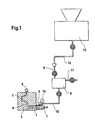
- Fig. 1 is a schematic representation of a die casting system according to the invention in the operating state.
- the die casting system shown first comprises a casting chamber 1 and one two-part mold 2, which is closed in the state shown.
- the casting chamber 1 is in the usual way via a pouring channel 4 with a Mold cavity 3 within the closed mold 2 in connection.
- the Mold cavity 3 is at its end remote from the casting chamber with a system 5 for Generating a vacuum connected within the mold cavity as they do is known from vacuum die casting machines.
- the casting chamber 1 has a metal filling opening 6 through which liquid Metal can be poured into the casting chamber.
- a casting piston 7 which is movable in the longitudinal direction of the casting chamber is arranged, the rest position in the schematic representation of FIG. 1 at the end of the casting chamber 1 remote from the casting channel.
- a metal filling device 13 which is based on conventional Way above the metal filling opening 6 is arranged.
- the system shown in Fig. 1 includes in addition to those previously mentioned usual components of a (vacuum) die casting machine a device 8 for vaporizing a release agent with a feed 9 for solid or liquid release agent and a release agent line 10 attached below for Introducing evaporated release agent into the casting chamber 1.
- the release agent evaporator 8 also has a carrier gas supply 11, which does not have a shown carrier gas source is connected; see. Fig. 5.
- the release agent line 10, in the gaseous release agent to the casting chamber 1 is the metal filling opening 6 of the casting chamber 1 assigned, cf. also Fig. 3.
- the feed 9 for solid release agent is available with a release agent metering device 12 in connection, in which sufficient amounts of release agent are stored become.
- the Release agent metering device 12 for example, solid release agent pellets can be found as in their own publication in the magazine Giesserei 84 (1997), No. 17, pages 43-46; the Release agent metering device 12 is then preferably a pneumatic metering device, that in connection with the feeder 9 via a plastic hose 14 stands, and the feed 9 then preferably comprises a cyclone.
- pellets are preferably made with a short Blast of compressed air out of the separator metering device 12 and through the transport hose transported into the cyclone (feeder), in which the air escapes and the pellets fall down by gravity.
- the still solid release material pellets arrive from the feed 9 in the release agent evaporator 8 (see FIG. 5), where it evaporates become.
- the carrier gas supply 11 becomes carrier gas introduced into the evaporator the release agent through line 10, which is typically a Copper pipe, and through the metal filler opening into the Casting chamber 1 initiated.
- the release agent reaches the mold cavity 3, and it can be found in the die casting machine takes the condensation processes according to the invention, which are based on the fact that the separating agent consists of one substance (or several Substances), their (respective) evaporation temperature at atmospheric pressure is higher than the temperature of the surface of the casting piston 7 and / or at least one inner wall of the casting chamber 1, the pouring channel 4 or the mold cavity 3 at the time of introducing the release agent the evaporator 8 into the die casting unit.
- the release agent is on the applied areas applied.
- FIG. 2 shows a system according to the invention in a highly schematic manner, to take place when a method according to the invention is carried out To illustrate processes.
- the evaporation temperature T 0 of the release agent is, for example, greater than T 4 (temperature of the casting piston surface before the mold is filled), condensation is possible at this location.
- the foundry specialist is able to determine or estimate the local temperatures before filling the mold. It gets these local temperatures with the evaporation temperatures compare possible release agents and then decide in individual cases, which release agent and, if applicable, which release agent / substance mixture he is using becomes.
- FIG. 3 the die casting system according to the invention according to FIG. 1 is a detail and shown in six different operating states, which are labeled with letters a to f.
- the system elements shown are identified by the reference symbols already used in FIG. 1, insofar as a label is required for understanding.
- Fig. 3a shows the die casting system according to the invention at the time of Introduction of a vaporized (gaseous) release agent according to the invention.
- the vacuum system 5 is turned on, which contributes to the fact that the gaseous Release agent quickly penetrates into the mold cavity 3 and fills it.
- the flow course of the supplied gaseous release agent is in Fig. 3a indicated by arrows.
- the condensation of the release agent in the die casting unit happens in the manner already described depending on the release agent evaporation temperature and the local wall temperatures inside the die casting unit.
- the casting piston 7 is at the introduction of the release agent in its resting position.
- the die casting system according to the invention is again at the time the introduction of a vaporized (gaseous) release agent according to the invention shown; however, the vacuum system 5 is switched off this time, and the Mold cavity 3 is only over the pouring channel 4 and the casting chamber 1 with the Environment in open communication.
- Fig. 3c is the operating state of the die casting system after the completion of Release agent discharge shown as it is when the vacuum system 5 is switched on is present. Air and any remaining gaseous release agent residues are removed withdrawn from the casting chamber through the mold cavity, which in turn is indicated by arrows.
- FIG. 3d The filling of the casting chamber 1 with liquid metal is shown in FIG. 3d.
- the inner walls of the casting chamber and the free surface of the Casting pistons are in this operating state with condensed release agent document that prevents a disturbing effect of the metal.
- 3f finally shows the die casting system with the mold 2 open (hatched). The solidified casting can be removed.
- FIG. 4 shows three operating positions of a die casting system according to the invention shown, the casting chamber 21 one of the metal filling opening spatially separate connection for introducing a vaporized separating material has.
- FIG. 4a shows the die casting system at the time of initiating a evaporated (gaseous) release agent according to the invention by an Line pipe 30 with the vacuum system 25 switched on.
- FIG. 4a corresponds insofar as the operating state shown in Fig. 3a.
- the plunger 27 has advanced somewhat from its rest position closes the metal filling opening 26; this way becomes a special one high pressure drop between the vacuum system 25 and the casting chamber 21 reached.
- the die casting system according to the invention is again at the time the introduction of a vaporized (gaseous) release agent according to the invention shown.
- the casting piston 27 is, however, in its rest position and the vacuum system 25 is switched off. To that extent corresponds to 4b the state shown in Fig. 3b.
- the separating material is swirled inside the casting chamber 21, that spreads from the point of discharge. What has been said about FIG. 3b applies analogous.
- FIG. 4c shows the filling of the casting chamber 21 with liquid Shown in metal.
- the casting piston 27 is in its rest position and opens the metal fill opening 26.
- Fig. 4c corresponds - except for the other arrangement of the separator line - Fig. 3d.
- FIG. 5 shows a device 28 for evaporating a release agent. It corresponds to device 8 according to FIG. 1.
- the separator evaporator 28 comprises a housing 31 made of a thermal insulating material that has an interior 32 for receiving a solid or liquid evaporable release agent.
- the fixed or Liquid release agent can be fed into the interior 32 by means of a feed 33 be entered.
- a carrier gas supply line 35 is also provided, by the carrier gases from a carrier gas source, not shown (for example a gas bottle) passed into the interior of the evaporator become.
- a separator gas line leads from the interior of the evaporator downwards 36 for a die casting unit not shown in FIG. 5, cf. 1.
- Feed 33, carrier gas supply line 35 and separator line 36 can independently of one another by means of controllable shut-off elements 43, 45 and 46 either locked or opened.
- shut-off element 43 of the feeder 33 When filling the solid or liquid separator in the interior of the evaporator 28 is for example only the shut-off element 43 of the feeder 33 is opened. After filling a batch of release agent to be evaporated is closed. Then be the heating elements 34, 34 'are activated and the release material evaporates, whereupon the shut-off element 46 of the separator gas line 36 and, if appropriate, that Shut-off element 45 of the carrier gas supply line 35 can be opened.
- the gaseous Release agent is then - optionally mixed with carrier gas - under Pressure is introduced into the die casting unit, not shown in FIG. 5, see. in particular FIGS. 3 and 4.
Landscapes
- Engineering & Computer Science (AREA)
- Mechanical Engineering (AREA)
- Mold Materials And Core Materials (AREA)
- Molds, Cores, And Manufacturing Methods Thereof (AREA)
- Lubricants (AREA)
- Casting Devices For Molds (AREA)
- Moulds For Moulding Plastics Or The Like (AREA)
Description
- der Trenn- oder Schmierstoff außerhalb der Druckgießeinheit verdampft wird,
- der verdampfte Trenn- oder Schmierstoff bei geschlossener Gießform in die Druckgießeinheit eingeleitet wird und
- eine zumindest partielle Kondensation des Trenn- oder Schmierstoffs auf der besagten Oberfläche und/oder zumindest einer besagten Innenwandung abgewartet wird, wobei
- der Trenn- oder Schmierstoff aus einer Substanz oder mehreren Substanzen besteht, deren jeweilige Verdampfungstemperatur bei Atmosphärendruck höher ist als die Temperatur der besagten Oberfläche und/oder zumindest einer besagten Innenwandung zum Zeitpunkt der Einleitung in die Druckgießeinheit.
- ein Trenn- oder Schmierstoff gemäß einem erfindungsgemäßen Applikations-Verfahren auf die Oberfläche eines Gießkolbens und/oder die Innenwandung einer Gießkammer, eines Gießkanals und/oder eines Formhohlraums einer Druckgießmaschine appliziert wird,
- ein flüssiges Metall in die Gießkammer der Druckgießmaschine eingefüllt wird und
- das flüssige Metall in den Formhohlraum der Druckgießmaschine gepreßt wird.
- Fig. 1
- Eine schematische Darstellung einer erfindungsgemäßen Anlage, umfassend eine Druckgießeinheit sowie eine Vorrichtung zum Einleiten verdampften Trennstoffs in die Druckgießeinheit.
- Fig. 2
- Eine stark schematische Darstellung einer erfindungsgemäßen Anlage zur Illustration typischer lokaler Temperaturen.
- Fig. 3
- Ein sechsteiliges Schema zur Ilustration einer erfindungsgemäßen Druckgießanlage, wobei der Trennstoff durch die Metall-Füllöffnung eingeleitet wird.
- Fig. 4
- Ein dreiteiliges Schema zur Ilustration einer erfindungsgemäßen Druckgießanlage, deren Gießkammer einen separaten Anschluß zur Einleitung eines verdampften Trennstoffs besitzt.
- Fig. 5
- Einen Trennstoff-Verdampfer zur Verwendung in einem erfindungsgemäßen Verfahren.
- T1 :
- Temperatur einer gießkammerfernen Innenwandung des Formhohlraums 3' vor der Formfüllung,
- T2 :
- Temperatur einer gießkammernahen Innenwandung des Formhohlraums 3' vor der Formfüllung,
- T3 :
- Temperatur am Übergang vom Gießkanal 4' zum Formhohlraum 3' vor der Formfüllung
- T4 :
- Temperatur der die Gießkammer begrenzenden Oberfläche des zugehörigen, nicht dargestellten Gießkolbens vor der Formfüllung.
- KT1 - KT4:
- Die entsprechenden Temperaturen während der Formfüllung
Claims (8)
- Verfahren zur Applikation eines Trenn- oder Schmierstoffs auf die Oberfläche eines Gießkolbens und/oder die Innenwandung einer Gießkammer, eines Gießkanals und/oder eines Formhohlraums einer Druckgießmaschine,
dadurch gekennzeichnet, daßder Trenn- oder Schmierstoff außerhalb der Druckgießeinheit verdampft wird,der verdampfte Trenn- oder Schmierstoff bei geschlossener Gießform in die Druckgießeinheit eingeleitet wird undeine zumindest partielle Kondensation des Trenn- oder Schmierstoffs auf der besagten Oberfläche und/oder zumindest einer besagten Innenwandung abgewartet wird, wobeider Trenn- oder Schmierstoff aus einer Substanz oder mehreren Substanzen besteht, deren jeweilige Verdampfungstemperatur bei Atmosphärendruck höher ist als die Temperatur der besagten Oberfläche und/oder zumindest einer besagten Innenwandung zum Zeitpunkt der Einleitung in die Druckgießeinheit. - Verfahren nach Anspruch 1, dadurch gekennzeichnet, daßder verdampfte Trenn- oder Schmierstoff mittels eines Druckimpulses in die Druckgießmaschine eingeleitet wird.
- Verfahren nach einem der vorangehenden Ansprüche, dadurch gekennzeichnet, daßder verdampfte Trenn- oder Schmierstoff im Gemisch mit einem Trägergas in die Druckgießeinheit eingeleitet wird.
- Verfahren nach einem der vorangehenden Ansprüche, dadurch gekennzeichnet, daßder Trenn- oder Schmierstoff im Bereich der Gießkammer in die Druckgießeinheit eingeleitet wird.
- Verfahren nach Anspruch 4, dadurch gekennzeichnet, daßvor und/oder während des Einleitens des Trenn- oder Schmierstoffs im Formhohlraum ein Druck eingestellt wird, der geringer ist als der Atmosphärendruck.
- Verfahren nach einem der vorangehenden Ansprüche, dadurch gekennzeichnet, daßder Trenn- oder Schmierstoff ein Substanzgemisch umfaßt, welches zumindest zwei Substanzen mit unterschiedlichen Verdampfungstemperaturen enthält.
- Druckgießverfahren, in demein Trenn- oder Schmierstoff gemäß einem Verfahren nach einem der vorangehenden Ansprüche auf die Oberfläche eines Gießkolbens und/oder die Innenwandung einer Gießkammer, eines Gießkanals und/oder eines Formhohlraums einer Druckgießmaschine appliziert wird,ein flüssiges Metall in die Gießkammer der Druckgießmaschine eingefüllt wird unddas flüssige Metall in den Formhohlraum der Druckgießmaschine gepreßt wird.
- Druckgießanlage zur Durchführung des Verfahrens nach Anspruch 7, umfassend eine Gießkammer und eine Gießform, dadurch gekennzeichnet, daß eine Vorrichtung zum Einleiten eines verdampften Trennstoffs in die Gießkammer vorgesehen ist.
Applications Claiming Priority (2)
| Application Number | Priority Date | Filing Date | Title |
|---|---|---|---|
| DE19840869 | 1998-08-31 | ||
| DE19840869 | 1998-08-31 |
Publications (2)
| Publication Number | Publication Date |
|---|---|
| EP0983812A1 EP0983812A1 (de) | 2000-03-08 |
| EP0983812B1 true EP0983812B1 (de) | 2002-11-27 |
Family
ID=7880145
Family Applications (1)
| Application Number | Title | Priority Date | Filing Date |
|---|---|---|---|
| EP99109269A Expired - Lifetime EP0983812B1 (de) | 1998-08-31 | 1999-05-26 | Verfahren zur Applikation eines Trenn- oder Schmierstoffs |
Country Status (5)
| Country | Link |
|---|---|
| EP (1) | EP0983812B1 (de) |
| JP (1) | JP2000071055A (de) |
| AT (1) | ATE228410T1 (de) |
| DE (2) | DE19906770C2 (de) |
| ES (1) | ES2186276T3 (de) |
Families Citing this family (4)
| Publication number | Priority date | Publication date | Assignee | Title |
|---|---|---|---|---|
| DE19945461A1 (de) * | 1999-09-22 | 2001-04-19 | Linde Gas Ag | Verfahren zur Verbesserung des Magnesium-Druckgußprozesses |
| JP3477124B2 (ja) * | 1999-10-21 | 2003-12-10 | 株式会社日本製鋼所 | 金属射出成形機における離型剤の塗布方法および金属射出成形用金型 |
| EP1820584A1 (de) * | 2006-02-21 | 2007-08-22 | Tribo-Chemie GmbH | Kaltkammer-Druckgießmaschine, Kaltkammer-Druckgießverfahren, und Kolbenschmiermittel dafür |
| DE102007020586A1 (de) * | 2007-05-02 | 2008-11-06 | Ashland-Südchemie-Kernfest GmbH | Beschichtungsmassen für Gießformen und Kerne zur Vermeidung von Reaktionsgasfehlern |
Family Cites Families (4)
| Publication number | Priority date | Publication date | Assignee | Title |
|---|---|---|---|---|
| DE3812634A1 (de) * | 1988-04-15 | 1989-10-26 | Sued Chemie Ag | Verfahren zur herstellung von giessformen aus tongebundenem formsand |
| DE4016368A1 (de) * | 1989-05-19 | 1990-12-13 | Theophil Bauer | Spruehkopf einer spruehvorrichtung zum aufspruehen von fluessigkeiten, insbesondere trennmitteln |
| US5662156A (en) * | 1995-12-05 | 1997-09-02 | Freeman; Lewis Gene | Method of die casting machine lubrication with unitized lubricant |
| JPH09276981A (ja) * | 1996-04-19 | 1997-10-28 | Taiho Kogyo Co Ltd | 金型成型用離型剤および鋳造プランジャ潤滑剤 |
-
1999
- 1999-02-17 DE DE19906770A patent/DE19906770C2/de not_active Expired - Fee Related
- 1999-05-26 EP EP99109269A patent/EP0983812B1/de not_active Expired - Lifetime
- 1999-05-26 DE DE59903523T patent/DE59903523D1/de not_active Expired - Lifetime
- 1999-05-26 ES ES99109269T patent/ES2186276T3/es not_active Expired - Lifetime
- 1999-05-26 AT AT99109269T patent/ATE228410T1/de active
- 1999-07-19 JP JP11204264A patent/JP2000071055A/ja active Pending
Also Published As
| Publication number | Publication date |
|---|---|
| DE19906770C2 (de) | 2003-03-27 |
| EP0983812A1 (de) | 2000-03-08 |
| DE59903523D1 (de) | 2003-01-09 |
| ATE228410T1 (de) | 2002-12-15 |
| JP2000071055A (ja) | 2000-03-07 |
| DE19906770A1 (de) | 2000-03-02 |
| ES2186276T3 (es) | 2003-05-01 |
Similar Documents
| Publication | Publication Date | Title |
|---|---|---|
| DE1291760B (de) | Verfahren und Vorrichtung zum diskontinuierlichen und kontinuierlichen Vakuum-Schmelzen und -Giessen von Staehlen und stahlaehnlichen Legierungen (Superiegierungen) | |
| DE10239817A1 (de) | Metallformungsverfahren und -gerät | |
| WO2019101436A1 (de) | Druckkopf für einen 3d-drucker und verfahren zur inbetriebnahme eines druckkopfes eines 3d-druckers | |
| WO2017050592A1 (de) | Druckkopf für den 3d-druck von metallen | |
| DE102007012370A1 (de) | Bedampfungseinrichtung und Bedampfungsverfahren zur Molekularstrahlbedampfung und Molekularstrahlepitaxie | |
| EP0983812A1 (de) | Verfahren zur Applikation eines Trenn- oder Schmierstoffs | |
| EP0612859A1 (de) | Niedervoltbogenverdampfer mit Nachfütterungseinrichtung und Verfahren zu dessen Verwendung | |
| DE102015100861B4 (de) | Heißkanal für eine Druckgussvorrichtung und Betriebsverfahren dafür | |
| WO2021078891A1 (de) | Vorrichtung und verfahren zum erzeugen und transportieren von trockeneispellets | |
| DE3206094C2 (de) | Diskontinuierliche Stranggießanlage | |
| AT506960B1 (de) | Verfahren zur herstellung einer gettereinrichtung | |
| DE1479763B1 (de) | Verfahren zum Kuehlen der Formteile von Form- oder Giessmaschinen zum Verarbeiten von thermoplastischem Kunststoff | |
| DE4319166C2 (de) | Verfahren und Vorrichtung zur Reinigung, insbesondere Entfettung und Kompaktierung von elektrisch leitfähigem Gut | |
| DE1433075A1 (de) | Vakuum-Schmelz- und-Giessverfahren und Vorrichtung zur Durchfuehrung desselben | |
| DD294200A5 (de) | Verfahren und vorrichtung zur fluessigmetallversorgung einer giessform | |
| DE102018203704A1 (de) | Verfahren zum Herstellen eines Bauteils und Vorrichtung zum Herstellen eines Bauteils | |
| DE102011012760A1 (de) | Strangpresse sowie Verfahren zum kontinuierlichen Pressen von Metall | |
| DE102021125159A1 (de) | Vorrichtung und ein Verfahren zum Herstellen eines Feingussbauteils | |
| AT230031B (de) | Vakuum-Schmelz- und -Gießverfahren und Vorrichtung zur Durchführung derselben | |
| DE102014114772A1 (de) | Vorrichtung zum Spritzgießen von Spritzgießteilen aus zum Spritzgießen geeignetem Werkstoff | |
| DE1458098A1 (de) | Vorrichtung und Verfahren zum Pressgiessen von Metall | |
| DE102019001258A1 (de) | Druckgießvorrichtung zum Gießen eines Bauteils sowie Verfahren zur Herstellung eines Bauteils | |
| EP0621065A1 (de) | Verfahren zur Trennung und Reinigung von Stoffen durch Schmelzkristallisation unter hohen Drücken | |
| DE69004496T2 (de) | Verfahren und Anlage zur Trennung der Bestandteile einer Legierung. | |
| EP3613520B1 (de) | Verfahren und vorrichtung zum vergiessen von metallen unter druck im kaltkammer |
Legal Events
| Date | Code | Title | Description |
|---|---|---|---|
| PUAI | Public reference made under article 153(3) epc to a published international application that has entered the european phase |
Free format text: ORIGINAL CODE: 0009012 |
|
| AK | Designated contracting states |
Kind code of ref document: A1 Designated state(s): AT DE ES FR GB IT SE |
|
| AX | Request for extension of the european patent |
Free format text: AL;LT;LV;MK;RO;SI |
|
| 17P | Request for examination filed |
Effective date: 20000816 |
|
| AKX | Designation fees paid |
Free format text: AT DE ES FR GB IT SE |
|
| RBV | Designated contracting states (corrected) |
Designated state(s): AT DE ES FR GB IT SE |
|
| GRAG | Despatch of communication of intention to grant |
Free format text: ORIGINAL CODE: EPIDOS AGRA |
|
| 17Q | First examination report despatched |
Effective date: 20020208 |
|
| GRAG | Despatch of communication of intention to grant |
Free format text: ORIGINAL CODE: EPIDOS AGRA |
|
| GRAG | Despatch of communication of intention to grant |
Free format text: ORIGINAL CODE: EPIDOS AGRA |
|
| GRAH | Despatch of communication of intention to grant a patent |
Free format text: ORIGINAL CODE: EPIDOS IGRA |
|
| GRAH | Despatch of communication of intention to grant a patent |
Free format text: ORIGINAL CODE: EPIDOS IGRA |
|
| GRAA | (expected) grant |
Free format text: ORIGINAL CODE: 0009210 |
|
| AK | Designated contracting states |
Kind code of ref document: B1 Designated state(s): AT DE ES FR GB IT SE |
|
| REF | Corresponds to: |
Ref document number: 228410 Country of ref document: AT Date of ref document: 20021215 Kind code of ref document: T |
|
| REG | Reference to a national code |
Ref country code: GB Ref legal event code: FG4D Free format text: NOT ENGLISH |
|
| REF | Corresponds to: |
Ref document number: 59903523 Country of ref document: DE Date of ref document: 20030109 |
|
| GBT | Gb: translation of ep patent filed (gb section 77(6)(a)/1977) |
Effective date: 20021219 |
|
| ET | Fr: translation filed | ||
| REG | Reference to a national code |
Ref country code: ES Ref legal event code: FG2A Ref document number: 2186276 Country of ref document: ES Kind code of ref document: T3 |
|
| PLBE | No opposition filed within time limit |
Free format text: ORIGINAL CODE: 0009261 |
|
| STAA | Information on the status of an ep patent application or granted ep patent |
Free format text: STATUS: NO OPPOSITION FILED WITHIN TIME LIMIT |
|
| 26N | No opposition filed |
Effective date: 20030828 |
|
| PGFP | Annual fee paid to national office [announced via postgrant information from national office to epo] |
Ref country code: ES Payment date: 20120525 Year of fee payment: 14 |
|
| PGFP | Annual fee paid to national office [announced via postgrant information from national office to epo] |
Ref country code: AT Payment date: 20120521 Year of fee payment: 14 |
|
| PGFP | Annual fee paid to national office [announced via postgrant information from national office to epo] |
Ref country code: SE Payment date: 20130521 Year of fee payment: 15 Ref country code: GB Payment date: 20130522 Year of fee payment: 15 Ref country code: DE Payment date: 20130603 Year of fee payment: 15 |
|
| PGFP | Annual fee paid to national office [announced via postgrant information from national office to epo] |
Ref country code: IT Payment date: 20130524 Year of fee payment: 15 Ref country code: FR Payment date: 20130604 Year of fee payment: 15 |
|
| REG | Reference to a national code |
Ref country code: DE Ref legal event code: R119 Ref document number: 59903523 Country of ref document: DE |
|
| REG | Reference to a national code |
Ref country code: AT Ref legal event code: MM01 Ref document number: 228410 Country of ref document: AT Kind code of ref document: T Effective date: 20140526 |
|
| GBPC | Gb: european patent ceased through non-payment of renewal fee |
Effective date: 20140526 |
|
| PG25 | Lapsed in a contracting state [announced via postgrant information from national office to epo] |
Ref country code: SE Free format text: LAPSE BECAUSE OF NON-PAYMENT OF DUE FEES Effective date: 20140527 |
|
| REG | Reference to a national code |
Ref country code: SE Ref legal event code: EUG |
|
| REG | Reference to a national code |
Ref country code: DE Ref legal event code: R119 Ref document number: 59903523 Country of ref document: DE Effective date: 20141202 |
|
| PG25 | Lapsed in a contracting state [announced via postgrant information from national office to epo] |
Ref country code: AT Free format text: LAPSE BECAUSE OF NON-PAYMENT OF DUE FEES Effective date: 20140526 |
|
| REG | Reference to a national code |
Ref country code: FR Ref legal event code: ST Effective date: 20150130 |
|
| PG25 | Lapsed in a contracting state [announced via postgrant information from national office to epo] |
Ref country code: IT Free format text: LAPSE BECAUSE OF NON-PAYMENT OF DUE FEES Effective date: 20140526 Ref country code: DE Free format text: LAPSE BECAUSE OF NON-PAYMENT OF DUE FEES Effective date: 20141202 |
|
| PG25 | Lapsed in a contracting state [announced via postgrant information from national office to epo] |
Ref country code: FR Free format text: LAPSE BECAUSE OF NON-PAYMENT OF DUE FEES Effective date: 20140602 Ref country code: GB Free format text: LAPSE BECAUSE OF NON-PAYMENT OF DUE FEES Effective date: 20140526 |
|
| REG | Reference to a national code |
Ref country code: ES Ref legal event code: FD2A Effective date: 20160205 |
|
| PG25 | Lapsed in a contracting state [announced via postgrant information from national office to epo] |
Ref country code: ES Free format text: LAPSE BECAUSE OF NON-PAYMENT OF DUE FEES Effective date: 20140527 |