EP0983811B1 - Drehdurchführung mit Kugelkopf - Google Patents
Drehdurchführung mit Kugelkopf Download PDFInfo
- Publication number
- EP0983811B1 EP0983811B1 EP99117148A EP99117148A EP0983811B1 EP 0983811 B1 EP0983811 B1 EP 0983811B1 EP 99117148 A EP99117148 A EP 99117148A EP 99117148 A EP99117148 A EP 99117148A EP 0983811 B1 EP0983811 B1 EP 0983811B1
- Authority
- EP
- European Patent Office
- Prior art keywords
- rotor
- housing
- roller
- rotatable lead
- spherical head
- Prior art date
- Legal status (The legal status is an assumption and is not a legal conclusion. Google has not performed a legal analysis and makes no representation as to the accuracy of the status listed.)
- Expired - Lifetime
Links
- 238000007789 sealing Methods 0.000 claims abstract description 21
- 238000009749 continuous casting Methods 0.000 claims abstract description 6
- 239000002826 coolant Substances 0.000 claims description 26
- 239000000463 material Substances 0.000 claims description 4
- 239000000314 lubricant Substances 0.000 claims 1
- 238000005096 rolling process Methods 0.000 claims 1
- XLYOFNOQVPJJNP-UHFFFAOYSA-N water Substances O XLYOFNOQVPJJNP-UHFFFAOYSA-N 0.000 description 5
- 229910000831 Steel Inorganic materials 0.000 description 3
- 239000010959 steel Substances 0.000 description 3
- 229910000906 Bronze Inorganic materials 0.000 description 2
- OKTJSMMVPCPJKN-UHFFFAOYSA-N Carbon Chemical compound [C] OKTJSMMVPCPJKN-UHFFFAOYSA-N 0.000 description 2
- 239000010974 bronze Substances 0.000 description 2
- 238000004140 cleaning Methods 0.000 description 2
- KUNSUQLRTQLHQQ-UHFFFAOYSA-N copper tin Chemical compound [Cu].[Sn] KUNSUQLRTQLHQQ-UHFFFAOYSA-N 0.000 description 2
- 238000005516 engineering process Methods 0.000 description 2
- 238000000034 method Methods 0.000 description 2
- 230000008646 thermal stress Effects 0.000 description 2
- 229910001369 Brass Inorganic materials 0.000 description 1
- 230000004323 axial length Effects 0.000 description 1
- 239000010951 brass Substances 0.000 description 1
- 229910052799 carbon Inorganic materials 0.000 description 1
- 238000010276 construction Methods 0.000 description 1
- 238000001816 cooling Methods 0.000 description 1
- 239000000498 cooling water Substances 0.000 description 1
- 230000000694 effects Effects 0.000 description 1
- 229920001971 elastomer Polymers 0.000 description 1
- 239000000806 elastomer Substances 0.000 description 1
- 229910002804 graphite Inorganic materials 0.000 description 1
- 239000010439 graphite Substances 0.000 description 1
- 238000003780 insertion Methods 0.000 description 1
- 230000037431 insertion Effects 0.000 description 1
- 239000007788 liquid Substances 0.000 description 1
- 230000000149 penetrating effect Effects 0.000 description 1
- 238000009420 retrofitting Methods 0.000 description 1
- 239000000565 sealant Substances 0.000 description 1
- HBMJWWWQQXIZIP-UHFFFAOYSA-N silicon carbide Chemical compound [Si+]#[C-] HBMJWWWQQXIZIP-UHFFFAOYSA-N 0.000 description 1
- 229910010271 silicon carbide Inorganic materials 0.000 description 1
- 125000006850 spacer group Chemical group 0.000 description 1
- 239000010935 stainless steel Substances 0.000 description 1
- 230000008719 thickening Effects 0.000 description 1
- 230000007704 transition Effects 0.000 description 1
Images
Classifications
-
- F—MECHANICAL ENGINEERING; LIGHTING; HEATING; WEAPONS; BLASTING
- F16—ENGINEERING ELEMENTS AND UNITS; GENERAL MEASURES FOR PRODUCING AND MAINTAINING EFFECTIVE FUNCTIONING OF MACHINES OR INSTALLATIONS; THERMAL INSULATION IN GENERAL
- F16L—PIPES; JOINTS OR FITTINGS FOR PIPES; SUPPORTS FOR PIPES, CABLES OR PROTECTIVE TUBING; MEANS FOR THERMAL INSULATION IN GENERAL
- F16L27/00—Adjustable joints; Joints allowing movement
- F16L27/08—Adjustable joints; Joints allowing movement allowing adjustment or movement only about the axis of one pipe
- F16L27/0804—Adjustable joints; Joints allowing movement allowing adjustment or movement only about the axis of one pipe the fluid passing axially from one joint element to another
- F16L27/0808—Adjustable joints; Joints allowing movement allowing adjustment or movement only about the axis of one pipe the fluid passing axially from one joint element to another the joint elements extending coaxially for some distance from their point of separation
- F16L27/0812—Adjustable joints; Joints allowing movement allowing adjustment or movement only about the axis of one pipe the fluid passing axially from one joint element to another the joint elements extending coaxially for some distance from their point of separation with slide bearings
- F16L27/082—Adjustable joints; Joints allowing movement allowing adjustment or movement only about the axis of one pipe the fluid passing axially from one joint element to another the joint elements extending coaxially for some distance from their point of separation with slide bearings having axial sealing
-
- B—PERFORMING OPERATIONS; TRANSPORTING
- B22—CASTING; POWDER METALLURGY
- B22D—CASTING OF METALS; CASTING OF OTHER SUBSTANCES BY THE SAME PROCESSES OR DEVICES
- B22D11/00—Continuous casting of metals, i.e. casting in indefinite lengths
- B22D11/12—Accessories for subsequent treating or working cast stock in situ
- B22D11/128—Accessories for subsequent treating or working cast stock in situ for removing
- B22D11/1287—Rolls; Lubricating, cooling or heating rolls while in use
Definitions
- the present invention relates to a rotating union the features of the preamble of claim 1.
- Rotary unions are available in different Industries, especially for continuous casting plants in the Steel industry needed.
- these continuous casting plants the runs red-hot steel in strand form over rollers, the outside in Bearings are rotatably supported in pedestals.
- These rollers are in a closed cycle by feeding Water under pressure inside the rollers to discharge the Heat cooled.
- the rotating union With the rotating union, the transition from the so-called rotor and the flange-mounted on it Cooling water pipe to the attached to the roller and itself thus sealed rotating housing.
- Rotary unions There are mainly two different types in the prior art known from rotary unions.
- a first embodiment of the Rotary unions have one outside the inside of the roll lying unit on which the components for the necessary Contains water supply, storage and seal. Due to the design have such systems with such rotary unions considerable width to the right and left of the pedestals.
- a technique used to seal off the rotation of the Roller moving relative to each other in a rotational movement Components of the rotating union are based on the use a radial seal consisting of circular 0-rings or Lip seals made of elastomer as the decisive one Sealing element.
- the object of the invention is achieved by provision a rotating union for connecting a coolant supply a roller, especially for continuous casting plants, which Spigot is supported in bearing blocks in roller bearings and the over axial bores are supplied with the coolant through the pins is, with a coolant supply and with a between Coolant supply and roller arranged rotor with a Rotor axially penetrating bore, being at one end the rotor a first sealing arrangement is provided and at the other end of the rotor the rotor shaft like a Ball head is formed with a sealing partner forms a second seal arrangement.
- the rotary union according to the invention has the advantages that it’s simple, an elevated one Wear resistance and reduced susceptibility to faults owns and thus enables extended downtimes.
- the Components used can be easily worn Replace.
- the ball head is in the Outside diameter the inside diameter of a ball head comprehensive cylindrical bore in the Coolant supply or the roller is provided adapted and can thus be used without the use of further sealants seal against the hole.
- a spherical head is a mobility of the rotor shaft in guaranteed axial and radial direction and so can Tipping moments due to load on the roller when guiding the slab intercepted by the roller or due to thermal stress become, resulting in less wear and longer service life of the rotating union.
- the ball head is with provided a circumferential groove in which a Seal, preferably an O-ring, is arranged and so improved sealing effect.
- a Seal preferably an O-ring
- the ball head from the end of the rotor shaft is preferred spaced, and there is an anti-rotation of the rotor on ball head end of the rotor shaft provided.
- the integrally formed hollow cylindrical rotor comprises a rotor shaft and is, optionally in an axial bore of a housing, rotatably mounted.
- One end is on the rotor a first seal arrangement (pair of seals) is provided.
- the sealing arrangement also through one another running flat surfaces on the rotor and the rotating partner of the rotor, which, for example, as part of a housing of the rotating union or can be formed in the coolant supply the use of at least one in one of the plane surfaces Integrated slide ring as a sealing element, which is usually made of Silicon carbide, carbon graphite or similar materials exists, preferred.
- One of these slip rings can be fixed Component be firmly anchored or spring-supported, wherein on its plan area the counterplan area of another, if necessary, spring-supported sliding ring as a rotating one Counter ring can expire.
- the axial length of the rotor is dimensioned so that on the the opposite side of the housing to the inside of the roller protruding rotor shaft end the coolant supply and / or - discharge, if necessary secured by an anti-rotation device, can be fixed.
- the rotor is usually made of one made of corrosion-resistant steel. It can be are preferably V2A or V4A steels.
- part of the Rotor shaft between ball head and first seal arrangement formed as an elastic region.
- the elastic range of the The rotor shaft can be provided with length compensation means is.
- the elastic region in shape a telescopic sleeve, which is preferably designed to be resilient can, or can be designed in the form of a compensator.
- the rotor shaft as elastic cylindrical sleeve can act on the rotor can be cushioned, and so the service life of the rotary union according to the invention can be increased.
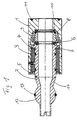
- FIG. 1 shows a schematic Cross-sectional view of an embodiment of the invention Rotating union.
- a housing (1) that can be inserted into the roller bore is a
- the rotor (2) is rotatably supported by the bearing bush (3) and lies there on the bearing bush (3) via a rotor collar and the Spacer ring (4).
- the bearing bush (3) is on the outside Seeger ring (5) secured.
- On the inside of the case facing end of the rotor is a slide ring (6) on an O-ring (7) spring-mounted.
- the slide ring (6) runs in the embodiment shown in the figure on the Pressure plate (8), which in turn is not one in the figure shown slide ring can wear.
- the pressure plate (8) is against twisting via dowel pins 9 secured.
- the pressure plate (8) is over the corrugated spring (10) against the housing (1) on the one hand and against the slide ring (6) on The rotor, on the other hand, is supported under tension.
- the housing 1 is against that not shown in the drawing Sealed roller over the O-ring (11).
- the rotor points to the from the housing projecting end section a spherical head Thickening (12), which has a groove in the middle, in the an O-ring (13) is mounted. This is done via the O-ring (13) Sealing against the cylindrical bore of the coolant or -discharge, which is not shown in the drawing.
- At the outside end of the rotor shaft can be diametrical arranged semicircular cutouts in the rotor shaft wall be provided as an anti-rotation device, which is one in the cylindrical bore of the not shown Grip coolant supply and crossbar prevent the rotor shaft from rotating.
- the one in the drawing is tapered towards the ball head tapering rotor shaft section (14) can preferably also in Form of a sealed, spring-loaded telescopic sleeve or one Compensator be designed and so greater mobility of the rotor shaft in the three spatial axes, if it allows due to the load on the roller and the roller bearing play Relative movements of the components comes to each other.
- the rotor is arranged between the rollers and the coolant supply, where either between the rotor and coolant supply Mechanical seal pair arrangement and on the inside of the roller arranged end of the rotor shaft a spherical head with in the circumference circumferential groove and O-ring arranged therein, or alternatively - as shown in the figure - the Mechanical seal assembly is between the rotor and Housing / roller arranged and the ball head is on the outside End of the rotor for insertion and sealing against the Coolant supply provided.
- the coolant supply can, as already mentioned above, be designed in the form of a lid in which the Coolant supply / s is / are integrated and the Bearing block covers to the outside.
Landscapes
- Engineering & Computer Science (AREA)
- General Engineering & Computer Science (AREA)
- Mechanical Engineering (AREA)
- Joints Allowing Movement (AREA)
- Mechanical Sealing (AREA)
- Pens And Brushes (AREA)
- Pivots And Pivotal Connections (AREA)
- Media Introduction/Drainage Providing Device (AREA)
- Rolls And Other Rotary Bodies (AREA)
- Mounting Of Bearings Or Others (AREA)
- Cylinder Crankcases Of Internal Combustion Engines (AREA)
Description
Claims (10)
- Drehdurchführung zum Anschluss einer Kühlmittelzuführung einer Walze, insbesondere für Stranggießanlagen, die über Zapfen in Lagerböcken in Wälzlagern gelagert ist und die über axiale Bohrungen durch die Zapfen mit dem Kühlmittel versorgt wird, mit einer Kühlmittelzuführung und mit einem zwischen Kühlmittelzuführung und Walze angeordneten Rotor (2) mit einer den Rotor (2) axial durchdringenden Bohrung, wobei an dem einen Ende des Rotors(2) eine erste Dichtungsanordnung (6;7;8) vorgesehen ist, dadurch gekennzeichnet, dass am anderen Ende des Rotors (2) der Rotorschaft nach Art eines Kugelkopfes (14) ausgebildet ist, der mit einem Dichtungspartner eine zweite Dichtungsanordnung ausbildet.
- Drehdurchführung nach Anspruch 1, dadurch gekennzeichnet, dass der Kugelkopf (12) eine umfangsmäßige verlaufende Nut aufweist, in der eine Dichtung (13) angeordnet ist.
- Drehdurchführung nach Anspruch 1 oder 2, dadurch gekennzeichnet, dass der Kugelkopf (12) vom Ende des Rotorschaftes beabstandet ist und eine Verdrehsicherung des Rotors am kugelkopfseitigen Ende des Rotorschaftes vorgesehen ist.
- Drehdurchführung nach einem der vorhergehenden Ansprüche, dadurch gekennzeichnet, dass der Rotorschaft (14) zwischen Kugelkopf (12) und erster Dichtungsanordnung (6;7;8) einen elastischen Bereich aufweist.
- Drehdurchführung nach Anspruch 4, dadurch gekennzeichnet, dass der elastische Bereich des Rotorschaftes (14) zwischen Kugelkopf und Dichtungsanordnung mit Längenausgleichsmitteln versehen ist.
- Drehdurchführung nach einem der vorhergehenden Ansprüche, dadurch gekennzeichnet, dass die erste Dichtungsanordnung in Form eines Gleitringpaares (6;7;8) ausgebildet ist, wobei der eine Gleitring auf dem Rotor (2), gegebenenfalls federnd abgestützt, angeordnet ist und der zweite Gleitring am Drehpartner des Rotors, gegebenenfalls federnd abgestützt, angeordnet ist.
- Drehdurchführung nach Anspruch 6, dadurch gekennzeichnet, dass der Drehpartner des Rotors (2) die Kühlmittelzuführung ist.
- Drehdurchführung nach Anspruch 6, dadurch gekennzeichnet, dass der Drehpartner des Rotors (2) ein den Rotor (2) aufnehmendes Gehäuse (1) oder ein Teil davon ist.
- Drehdurchführung nach Anspruch 8, wobei der Rotor (2) im Gehäuse (1) drehbar gelagert ist, der Gleitring (6) auf dem im Gehäuse (1) befindlichen Ende des einstückigen Rotors (2) festgelegt ist und sich mit dem Rotor mitdreht, der zweite Gleitring, der auf dem ersten Gleitring abläuft, von einem in das Gehäuse (1) an der dem Walzeninneren zugewandten Ende des Gehäuses (1) eingepassten Deckel getragen wird, und eine den Rotor (2) und den Deckel durchdringende axiale Bohrung vorgesehen ist, wobei der Rotorschaft an der, dem Walzeninneren abgewandten Seite des Gehäuses (1) einen aus dem Gehäuse überstehenden Endabschnitt mit einem Kugelkopf (12) aufweist, an den eine vorzugsweise zylindrische Bohrung der Kühlmittelzu-, bzw. abführung dichtend angepasst ist.
- Drehdurchführung nach Anspruch 9, dadurch gekennzeichnet, dass zwischen Rotor (2) und Gehäuse (1) eine Lagerbuchse aus einem schmierfähigen Material (3) angeordnet ist.
Applications Claiming Priority (2)
| Application Number | Priority Date | Filing Date | Title |
|---|---|---|---|
| DE19840043 | 1998-09-02 | ||
| DE19840043A DE19840043C1 (de) | 1998-09-02 | 1998-09-02 | Drehdurchführung mit Kugelkopf |
Publications (2)
| Publication Number | Publication Date |
|---|---|
| EP0983811A1 EP0983811A1 (de) | 2000-03-08 |
| EP0983811B1 true EP0983811B1 (de) | 2002-05-08 |
Family
ID=7879596
Family Applications (1)
| Application Number | Title | Priority Date | Filing Date |
|---|---|---|---|
| EP99117148A Expired - Lifetime EP0983811B1 (de) | 1998-09-02 | 1999-08-31 | Drehdurchführung mit Kugelkopf |
Country Status (5)
| Country | Link |
|---|---|
| EP (1) | EP0983811B1 (de) |
| AT (1) | ATE217222T1 (de) |
| DE (2) | DE19840043C1 (de) |
| ES (1) | ES2179579T3 (de) |
| TW (1) | TW396074B (de) |
Families Citing this family (7)
| Publication number | Priority date | Publication date | Assignee | Title |
|---|---|---|---|---|
| DE102004056818B3 (de) * | 2004-11-24 | 2006-08-17 | Deublin Gmbh | Drehdurchführung |
| US11123909B2 (en) | 2013-07-19 | 2021-09-21 | Windmöller & Heilscher KG | Apparatus for producing films stretched in-line |
| DE202014102267U1 (de) | 2014-05-14 | 2014-06-06 | Buchen Umweltservice Gmbh | MHM-Drehmotor |
| CN105449942B (zh) * | 2015-12-31 | 2017-11-28 | 上海振华重工集团(南通)传动机械有限公司 | 一种可旋转式电机试车工装 |
| CN106424615A (zh) * | 2016-07-13 | 2017-02-22 | 江苏东顺新能源科技有限公司 | 一种铅板轧辊的冷却装置 |
| CN111906269A (zh) * | 2020-08-07 | 2020-11-10 | 云南玉溪玉昆钢铁集团有限公司 | 一种便拆式耐磨型新型炼钢厂连铸机钢坯输送辊 |
| CN114542826B (zh) * | 2022-01-10 | 2023-05-30 | 重庆电子工程职业学院 | 一种芯片制造保护气体流量控制装置 |
Family Cites Families (9)
| Publication number | Priority date | Publication date | Assignee | Title |
|---|---|---|---|---|
| GB2046386B (en) * | 1979-04-12 | 1983-02-23 | Aeroquip Ltd | Liquid-tight rotary pipe joint |
| DE3526704A1 (de) * | 1985-07-25 | 1987-02-05 | Thyssen Plastik Anger Kg | Gelenkelement fuer rohre oder dergl. |
| US4976282A (en) * | 1989-04-12 | 1990-12-11 | Deublin Company | Coolant union with fluid actuated seal assembly |
| DE4207042C1 (en) * | 1992-03-02 | 1993-09-16 | Mannesmann Ag, 40213 Duesseldorf, De | Coolant coupling for roll device - with good sealant properties provided by elastic socket feeding coolant into roll bore |
| IT1264307B1 (it) * | 1993-10-12 | 1996-09-23 | Franco Frascaroli | Dispositivo per il collegamento di tubazioni per fluidi a relativi organi erogatori. |
| US5992901A (en) * | 1995-10-27 | 1999-11-30 | Mannesmann Ag | Device for coupling a coolant duct of a rotating part |
| DE19541615C1 (de) * | 1995-11-08 | 1997-07-10 | Thyssen Stahl Ag | Drehdurchführung für die Kühlwasserzu- und ableitung einer Führungsrolle in einer Stranggießanlage |
| DE19605797C2 (de) * | 1996-02-16 | 2002-11-14 | Georg Springmann Ind Und Bergb | Drehdurchführung |
| DE19613032C1 (de) * | 1996-03-19 | 1997-06-12 | Mannesmann Ag | Vorrichtung zum Ankuppeln der Fluidführung eines drehgelagerten Rotationsteiles |
-
1998
- 1998-09-02 DE DE19840043A patent/DE19840043C1/de not_active Expired - Fee Related
-
1999
- 1999-07-30 TW TW088112953A patent/TW396074B/zh not_active IP Right Cessation
- 1999-08-31 AT AT99117148T patent/ATE217222T1/de not_active IP Right Cessation
- 1999-08-31 ES ES99117148T patent/ES2179579T3/es not_active Expired - Lifetime
- 1999-08-31 EP EP99117148A patent/EP0983811B1/de not_active Expired - Lifetime
- 1999-08-31 DE DE59901385T patent/DE59901385D1/de not_active Expired - Fee Related
Also Published As
| Publication number | Publication date |
|---|---|
| EP0983811A1 (de) | 2000-03-08 |
| TW396074B (en) | 2000-07-01 |
| ES2179579T3 (es) | 2003-01-16 |
| DE19840043C1 (de) | 1999-12-09 |
| DE59901385D1 (de) | 2002-06-13 |
| ATE217222T1 (de) | 2002-05-15 |
Similar Documents
| Publication | Publication Date | Title |
|---|---|---|
| DE10135533B4 (de) | Drehgelenk für Hochdruckvorrichtungen für die Verbindung eines nicht drehenden Teiles mit einem drehenden Teil | |
| DE69310494T2 (de) | Hochgeschwindigkeitsdrehverbindung | |
| DE4207042C1 (en) | Coolant coupling for roll device - with good sealant properties provided by elastic socket feeding coolant into roll bore | |
| DE19541131C1 (de) | Vorrichtung zum Ankuppeln der Kühlmedienführung eines Rotationsteiles | |
| DE19840043C1 (de) | Drehdurchführung mit Kugelkopf | |
| DE19541615C1 (de) | Drehdurchführung für die Kühlwasserzu- und ableitung einer Führungsrolle in einer Stranggießanlage | |
| DE2509751A1 (de) | Wellen-abdichtung | |
| DE19605797C2 (de) | Drehdurchführung | |
| DE19613032C1 (de) | Vorrichtung zum Ankuppeln der Fluidführung eines drehgelagerten Rotationsteiles | |
| EP1269063B1 (de) | Drehdurchführung | |
| DE2710236A1 (de) | Schraubenpumpe | |
| EP1613441B2 (de) | Vorrichtung zum ankuppeln einer kühlmittelzuführung an eine walze | |
| DE102004056818B3 (de) | Drehdurchführung | |
| EP1446604B1 (de) | Anschlussblock für hydraulik-versorgungsleitungen der hydrostatikanlage eines ölfilmlagers | |
| DE20023231U1 (de) | Lagerung mit Drehdurchführung | |
| DE68910289T2 (de) | Drehkupplung. | |
| DE4214211C1 (en) | Rotating pressure coupling - has rotor and housing having inlets leading to chamber sealed by rings which are lubricated, rotor moves axially by groove and cam | |
| DE10327723B3 (de) | Dreheinführung | |
| DE19823669C1 (de) | Kompensator-Dreheinführung | |
| DE19605798A1 (de) | Drehdurchführung mit über Wälzlager im Gehäuse gelagertem Rotor | |
| DE102004038225A1 (de) | Vorrichtung zum Ankuppeln einer Kühlmittelzuführung an eine Walze mit Kompensator und mit Rückstellmitteln | |
| DE10327716B3 (de) | Dreheinführung | |
| DE1962678C3 (de) | Anordnung zur zwangsweisen Langs fuhrung von rotierenden Trommeln | |
| DE202022100246U1 (de) | Drehdurchführung für ein Getriebe | |
| DE1961870A1 (de) | Drehgelenk fuer Rohrleitungen,mit auswechselbaren Gleitringen und Dichtungen;Dichtungen,die nicht direkt vom Durchflussmedium beruehrt werden |
Legal Events
| Date | Code | Title | Description |
|---|---|---|---|
| PUAI | Public reference made under article 153(3) epc to a published international application that has entered the european phase |
Free format text: ORIGINAL CODE: 0009012 |
|
| AK | Designated contracting states |
Kind code of ref document: A1 Designated state(s): AT BE CH CY DE DK ES FI FR GB GR IE IT LI LU MC NL PT SE |
|
| AX | Request for extension of the european patent |
Free format text: AL;LT;LV;MK;RO;SI |
|
| 17P | Request for examination filed |
Effective date: 20000831 |
|
| RIN1 | Information on inventor provided before grant (corrected) |
Inventor name: HASSELBRINK, DIRK Inventor name: WARMBIER, DIETER Inventor name: SPRINGMANN, GEORG |
|
| AKX | Designation fees paid |
Free format text: AT BE CH CY DE DK ES FI FR GB GR IE IT LI LU MC NL PT SE |
|
| 17Q | First examination report despatched |
Effective date: 20010403 |
|
| GRAG | Despatch of communication of intention to grant |
Free format text: ORIGINAL CODE: EPIDOS AGRA |
|
| GRAG | Despatch of communication of intention to grant |
Free format text: ORIGINAL CODE: EPIDOS AGRA |
|
| GRAH | Despatch of communication of intention to grant a patent |
Free format text: ORIGINAL CODE: EPIDOS IGRA |
|
| REG | Reference to a national code |
Ref country code: GB Ref legal event code: IF02 |
|
| GRAH | Despatch of communication of intention to grant a patent |
Free format text: ORIGINAL CODE: EPIDOS IGRA |
|
| GRAA | (expected) grant |
Free format text: ORIGINAL CODE: 0009210 |
|
| AK | Designated contracting states |
Kind code of ref document: B1 Designated state(s): AT BE CH CY DE DK ES FI FR GB GR IE IT LI LU MC NL PT SE |
|
| PG25 | Lapsed in a contracting state [announced via postgrant information from national office to epo] |
Ref country code: IT Free format text: LAPSE BECAUSE OF FAILURE TO SUBMIT A TRANSLATION OF THE DESCRIPTION OR TO PAY THE FEE WITHIN THE PRESCRIBED TIME-LIMIT;WARNING: LAPSES OF ITALIAN PATENTS WITH EFFECTIVE DATE BEFORE 2007 MAY HAVE OCCURRED AT ANY TIME BEFORE 2007. THE CORRECT EFFECTIVE DATE MAY BE DIFFERENT FROM THE ONE RECORDED. Effective date: 20020508 Ref country code: IE Free format text: LAPSE BECAUSE OF FAILURE TO SUBMIT A TRANSLATION OF THE DESCRIPTION OR TO PAY THE FEE WITHIN THE PRESCRIBED TIME-LIMIT Effective date: 20020508 Ref country code: GR Free format text: LAPSE BECAUSE OF FAILURE TO SUBMIT A TRANSLATION OF THE DESCRIPTION OR TO PAY THE FEE WITHIN THE PRESCRIBED TIME-LIMIT Effective date: 20020508 |
|
| REF | Corresponds to: |
Ref document number: 217222 Country of ref document: AT Date of ref document: 20020515 Kind code of ref document: T |
|
| REG | Reference to a national code |
Ref country code: CH Ref legal event code: EP |
|
| REG | Reference to a national code |
Ref country code: IE Ref legal event code: FG4D Free format text: GERMAN |
|
| REF | Corresponds to: |
Ref document number: 59901385 Country of ref document: DE Date of ref document: 20020613 |
|
| PG25 | Lapsed in a contracting state [announced via postgrant information from national office to epo] |
Ref country code: SE Free format text: LAPSE BECAUSE OF FAILURE TO SUBMIT A TRANSLATION OF THE DESCRIPTION OR TO PAY THE FEE WITHIN THE PRESCRIBED TIME-LIMIT Effective date: 20020808 Ref country code: PT Free format text: LAPSE BECAUSE OF FAILURE TO SUBMIT A TRANSLATION OF THE DESCRIPTION OR TO PAY THE FEE WITHIN THE PRESCRIBED TIME-LIMIT Effective date: 20020808 Ref country code: DK Free format text: LAPSE BECAUSE OF FAILURE TO SUBMIT A TRANSLATION OF THE DESCRIPTION OR TO PAY THE FEE WITHIN THE PRESCRIBED TIME-LIMIT Effective date: 20020808 |
|
| GBT | Gb: translation of ep patent filed (gb section 77(6)(a)/1977) |
Effective date: 20020724 |
|
| PGFP | Annual fee paid to national office [announced via postgrant information from national office to epo] |
Ref country code: FR Payment date: 20020819 Year of fee payment: 4 |
|
| PGFP | Annual fee paid to national office [announced via postgrant information from national office to epo] |
Ref country code: ES Payment date: 20020826 Year of fee payment: 4 |
|
| PG25 | Lapsed in a contracting state [announced via postgrant information from national office to epo] |
Ref country code: CY Free format text: LAPSE BECAUSE OF FAILURE TO SUBMIT A TRANSLATION OF THE DESCRIPTION OR TO PAY THE FEE WITHIN THE PRESCRIBED TIME-LIMIT Effective date: 20020831 |
|
| ET | Fr: translation filed | ||
| REG | Reference to a national code |
Ref country code: IE Ref legal event code: FD4D Ref document number: 0983811E Country of ref document: IE |
|
| REG | Reference to a national code |
Ref country code: ES Ref legal event code: FG2A Ref document number: 2179579 Country of ref document: ES Kind code of ref document: T3 |
|
| PG25 | Lapsed in a contracting state [announced via postgrant information from national office to epo] |
Ref country code: MC Free format text: LAPSE BECAUSE OF NON-PAYMENT OF DUE FEES Effective date: 20030301 |
|
| PLBE | No opposition filed within time limit |
Free format text: ORIGINAL CODE: 0009261 |
|
| STAA | Information on the status of an ep patent application or granted ep patent |
Free format text: STATUS: NO OPPOSITION FILED WITHIN TIME LIMIT |
|
| 26N | No opposition filed |
Effective date: 20030211 |
|
| PG25 | Lapsed in a contracting state [announced via postgrant information from national office to epo] |
Ref country code: GB Free format text: LAPSE BECAUSE OF NON-PAYMENT OF DUE FEES Effective date: 20030831 |
|
| PG25 | Lapsed in a contracting state [announced via postgrant information from national office to epo] |
Ref country code: ES Free format text: LAPSE BECAUSE OF NON-PAYMENT OF DUE FEES Effective date: 20030901 |
|
| GBPC | Gb: european patent ceased through non-payment of renewal fee | ||
| PG25 | Lapsed in a contracting state [announced via postgrant information from national office to epo] |
Ref country code: FR Free format text: LAPSE BECAUSE OF NON-PAYMENT OF DUE FEES Effective date: 20040430 |
|
| REG | Reference to a national code |
Ref country code: FR Ref legal event code: ST |
|
| PGFP | Annual fee paid to national office [announced via postgrant information from national office to epo] |
Ref country code: NL Payment date: 20040819 Year of fee payment: 6 |
|
| PGFP | Annual fee paid to national office [announced via postgrant information from national office to epo] |
Ref country code: FI Payment date: 20040823 Year of fee payment: 6 Ref country code: BE Payment date: 20040823 Year of fee payment: 6 |
|
| PGFP | Annual fee paid to national office [announced via postgrant information from national office to epo] |
Ref country code: LU Payment date: 20040824 Year of fee payment: 6 Ref country code: CH Payment date: 20040824 Year of fee payment: 6 Ref country code: AT Payment date: 20040824 Year of fee payment: 6 |
|
| REG | Reference to a national code |
Ref country code: ES Ref legal event code: FD2A Effective date: 20030901 |
|
| PG25 | Lapsed in a contracting state [announced via postgrant information from national office to epo] |
Ref country code: LU Free format text: LAPSE BECAUSE OF NON-PAYMENT OF DUE FEES Effective date: 20050831 Ref country code: LI Free format text: LAPSE BECAUSE OF NON-PAYMENT OF DUE FEES Effective date: 20050831 Ref country code: FI Free format text: LAPSE BECAUSE OF NON-PAYMENT OF DUE FEES Effective date: 20050831 Ref country code: CH Free format text: LAPSE BECAUSE OF NON-PAYMENT OF DUE FEES Effective date: 20050831 Ref country code: BE Free format text: LAPSE BECAUSE OF NON-PAYMENT OF DUE FEES Effective date: 20050831 Ref country code: AT Free format text: LAPSE BECAUSE OF NON-PAYMENT OF DUE FEES Effective date: 20050831 |
|
| PG25 | Lapsed in a contracting state [announced via postgrant information from national office to epo] |
Ref country code: NL Free format text: LAPSE BECAUSE OF NON-PAYMENT OF DUE FEES Effective date: 20060301 |
|
| REG | Reference to a national code |
Ref country code: CH Ref legal event code: PL |
|
| NLV4 | Nl: lapsed or anulled due to non-payment of the annual fee |
Effective date: 20060301 |
|
| BERE | Be: lapsed |
Owner name: GEORG *SPRINGMANN INDUSTRIE- UND BERGBAUTECHNIK G. Effective date: 20050831 |
|
| PGFP | Annual fee paid to national office [announced via postgrant information from national office to epo] |
Ref country code: DE Payment date: 20081031 Year of fee payment: 10 |
|
| PG25 | Lapsed in a contracting state [announced via postgrant information from national office to epo] |
Ref country code: DE Free format text: LAPSE BECAUSE OF NON-PAYMENT OF DUE FEES Effective date: 20100302 |