EP0983414B1 - Control assembly for lift gate or sliding and cargo doors - Google Patents
Control assembly for lift gate or sliding and cargo doors Download PDFInfo
- Publication number
- EP0983414B1 EP0983414B1 EP98916748A EP98916748A EP0983414B1 EP 0983414 B1 EP0983414 B1 EP 0983414B1 EP 98916748 A EP98916748 A EP 98916748A EP 98916748 A EP98916748 A EP 98916748A EP 0983414 B1 EP0983414 B1 EP 0983414B1
- Authority
- EP
- European Patent Office
- Prior art keywords
- lever
- control assembly
- output lever
- output
- input
- Prior art date
- Legal status (The legal status is an assumption and is not a legal conclusion. Google has not performed a legal analysis and makes no representation as to the accuracy of the status listed.)
- Expired - Lifetime
Links
- 230000001419 dependent effect Effects 0.000 claims abstract description 3
- 230000000694 effects Effects 0.000 claims description 3
- 239000002184 metal Substances 0.000 description 4
- 230000007246 mechanism Effects 0.000 description 2
- 241000251468 Actinopterygii Species 0.000 description 1
- 230000000295 complement effect Effects 0.000 description 1
Images


Classifications
-
- E—FIXED CONSTRUCTIONS
- E05—LOCKS; KEYS; WINDOW OR DOOR FITTINGS; SAFES
- E05B—LOCKS; ACCESSORIES THEREFOR; HANDCUFFS
- E05B81/00—Power-actuated vehicle locks
- E05B81/02—Power-actuated vehicle locks characterised by the type of actuators used
- E05B81/04—Electrical
- E05B81/06—Electrical using rotary motors
-
- E—FIXED CONSTRUCTIONS
- E05—LOCKS; KEYS; WINDOW OR DOOR FITTINGS; SAFES
- E05B—LOCKS; ACCESSORIES THEREFOR; HANDCUFFS
- E05B79/00—Mounting or connecting vehicle locks or parts thereof
- E05B79/10—Connections between movable lock parts
- E05B79/20—Connections between movable lock parts using flexible connections, e.g. Bowden cables
-
- E—FIXED CONSTRUCTIONS
- E05—LOCKS; KEYS; WINDOW OR DOOR FITTINGS; SAFES
- E05B—LOCKS; ACCESSORIES THEREFOR; HANDCUFFS
- E05B81/00—Power-actuated vehicle locks
- E05B81/12—Power-actuated vehicle locks characterised by the function or purpose of the powered actuators
- E05B81/16—Power-actuated vehicle locks characterised by the function or purpose of the powered actuators operating on locking elements for locking or unlocking action
-
- E—FIXED CONSTRUCTIONS
- E05—LOCKS; KEYS; WINDOW OR DOOR FITTINGS; SAFES
- E05B—LOCKS; ACCESSORIES THEREFOR; HANDCUFFS
- E05B81/00—Power-actuated vehicle locks
- E05B81/24—Power-actuated vehicle locks characterised by constructional features of the actuator or the power transmission
- E05B81/25—Actuators mounted separately from the lock and controlling the lock functions through mechanical connections
-
- E—FIXED CONSTRUCTIONS
- E05—LOCKS; KEYS; WINDOW OR DOOR FITTINGS; SAFES
- E05B—LOCKS; ACCESSORIES THEREFOR; HANDCUFFS
- E05B83/00—Vehicle locks specially adapted for particular types of wing or vehicle
- E05B83/16—Locks for luggage compartments, car boot lids or car bonnets
-
- E—FIXED CONSTRUCTIONS
- E05—LOCKS; KEYS; WINDOW OR DOOR FITTINGS; SAFES
- E05B—LOCKS; ACCESSORIES THEREFOR; HANDCUFFS
- E05B83/00—Vehicle locks specially adapted for particular types of wing or vehicle
- E05B83/36—Locks for passenger or like doors
-
- E—FIXED CONSTRUCTIONS
- E05—LOCKS; KEYS; WINDOW OR DOOR FITTINGS; SAFES
- E05B—LOCKS; ACCESSORIES THEREFOR; HANDCUFFS
- E05B63/00—Locks or fastenings with special structural characteristics
- E05B63/14—Arrangement of several locks or locks with several bolts, e.g. arranged one behind the other
- E05B63/143—Arrangement of several locks, e.g. in parallel or series, on one or more wings
-
- E—FIXED CONSTRUCTIONS
- E05—LOCKS; KEYS; WINDOW OR DOOR FITTINGS; SAFES
- E05B—LOCKS; ACCESSORIES THEREFOR; HANDCUFFS
- E05B77/00—Vehicle locks characterised by special functions or purposes
- E05B77/22—Functions related to actuation of locks from the passenger compartment of the vehicle
- E05B77/24—Functions related to actuation of locks from the passenger compartment of the vehicle preventing use of an inner door handle, sill button, lock knob or the like
- E05B77/26—Functions related to actuation of locks from the passenger compartment of the vehicle preventing use of an inner door handle, sill button, lock knob or the like specially adapted for child safety
- E05B77/265—Functions related to actuation of locks from the passenger compartment of the vehicle preventing use of an inner door handle, sill button, lock knob or the like specially adapted for child safety hand actuated, e.g. by a lever at the edge of the door
-
- E—FIXED CONSTRUCTIONS
- E05—LOCKS; KEYS; WINDOW OR DOOR FITTINGS; SAFES
- E05B—LOCKS; ACCESSORIES THEREFOR; HANDCUFFS
- E05B81/00—Power-actuated vehicle locks
- E05B81/54—Electrical circuits
- E05B81/90—Manual override in case of power failure
-
- Y—GENERAL TAGGING OF NEW TECHNOLOGICAL DEVELOPMENTS; GENERAL TAGGING OF CROSS-SECTIONAL TECHNOLOGIES SPANNING OVER SEVERAL SECTIONS OF THE IPC; TECHNICAL SUBJECTS COVERED BY FORMER USPC CROSS-REFERENCE ART COLLECTIONS [XRACs] AND DIGESTS
- Y10—TECHNICAL SUBJECTS COVERED BY FORMER USPC
- Y10T—TECHNICAL SUBJECTS COVERED BY FORMER US CLASSIFICATION
- Y10T292/00—Closure fasteners
- Y10T292/08—Bolts
- Y10T292/1043—Swinging
- Y10T292/1044—Multiple head
- Y10T292/1045—Operating means
- Y10T292/1047—Closure
-
- Y—GENERAL TAGGING OF NEW TECHNOLOGICAL DEVELOPMENTS; GENERAL TAGGING OF CROSS-SECTIONAL TECHNOLOGIES SPANNING OVER SEVERAL SECTIONS OF THE IPC; TECHNICAL SUBJECTS COVERED BY FORMER USPC CROSS-REFERENCE ART COLLECTIONS [XRACs] AND DIGESTS
- Y10—TECHNICAL SUBJECTS COVERED BY FORMER USPC
- Y10T—TECHNICAL SUBJECTS COVERED BY FORMER US CLASSIFICATION
- Y10T292/00—Closure fasteners
- Y10T292/08—Bolts
- Y10T292/1043—Swinging
- Y10T292/1075—Operating means
- Y10T292/1082—Motor
Definitions
- This invention relates to closure members for vehicles which close a compartment such as a tailgate, a cargo door, or a sliding door or the like.
- the door is typically moved, for example pivoted or slid from a closed position to an open position.
- a handle In order to effect this movement, a handle must be operated through a control assembly to release the latch mechanisms allowing the closure to be moved to the open position.
- This present invention finds particular application therefore in providing such a control assembly which has simplified the structures heretofore known reducing the number of parts thereof and increasing the reliability thereof while reducing the overall power consumption required in a preferably power actuated control assembly.
- United States Patent No. 5,531,4908 refers to a power lift-type tailgate and includes a control assembly which is cable driven once the latches are released.
- the drive includes a motor driving a cable reel to lift the tailgate assembly.
- Such a control assembly therefore includes a first pivot connected to the locking lever, a second pivot connected with the floating pin, a third pivot about which the locking lever pivots, and a fourth pivot about which the input lever and the output lever pivot.
- a latch control assembly having a simple mechanism for locking and unlocking a lift gate or door and for effecting unlatching thereof.
- a control assembly for releasing a latch.
- the control assembly has a base plate for mounting components of the control assembly.
- a pivotally mounted input lever is movable between a ready position and a release position. The input lever connects to a release handle.
- a pivotally mounted output lever connects to a latch and transmits a releasing force.
- a pivotally mounted locking lever is rotatable between a locked position and an unlocked position.
- a link slidably engages the output lever and pivotally engages the locking lever. When the locking lever moves between the locked and unlocked positions, the link responsively decouples and couples the input lever and the output lever to allow independent and dependent rotation thereof, respectively, selectively transferring the releasing force from the release handle to the latch.
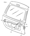
- FIG. 1 there is illustrated a tailgate assembly or door assembly 12, normally pivotally mounted, which allows the door 12 to swing upwardly in the conventional motion of a tailgate.
- Two latches, 14 and 16 are conveniently located proximate the sides of the tailgate 12 which will engage keepers or strikers when the tailgate 12 is closed.
- the latches 14, 16 are oriented in such a way that the fish mouths will engage with the respective strikers as is well known in the art.
- the latches 14, 16 are conventional an include pawl release levers to which are connected the Bowden cables 18, 20 for each latch.
- the Bowden cables 18, 20 are conveniently run through clips in openings in the body panels which allow motion of the cable and yet securement of the cable in relation to the panel.
- the Bowden cables 18, 20 operatively connect to the control assembly 10 of the present invention.
- Release handle 22 is operatively connected via a cable or rod 24 to the input lever of control assembly 10.
- Release handle 22 is pivotally mounted to the tailgate 12 in a manner conventional in the art. Actuation of the release handle 22 effects the release of the latches 14, 18 when the control assembly 10 is in the operative or unlocked position which will be described hereinafter.
- control assembly 10 which includes a mounting or base plate 26, an input lever 28, an output lever 30, a locking block 32, a locking lever 34 and an actuator 36.
- Base plate 26 is preferably a stamped metal formed with various features including mounting holes, Bowden cable attachment tabs 38, 40, an arcuate guide slot 42, and a control window 44.
- Tabs 38, 40 extend generally perpendicular from base plate 26.
- Tabs 38 and 40 have cutouts for receiving the outer cable shell or sheath of Bowden cables 18, 20.
- Base plate 26 has an embossed area 46 having a bore 48 and an embossed area 50 having a bore 52.
- Base plate 26 is otherwise configured for mounting the components of the control assembly 10 onto the base plate 26 and for matching the footprint for mounting the control assembly 10 onto the frame of the lift gate 12.
- Input lever 28 is preferably a stamped metal and formed to be pivotally mounted onto base plate 26.
- Input lever 28 has two arms 54, 56 extending from opposite sides of pivot 58.
- Arm 54 has tabs 60, 62 extending in opposite directions.
- Tab 62 extends towards the base plate 26 and extends through control window 44.
- Control window 44 limits the pivotal travel of the input lever 28 between a ready position and a release position.
- Arm 56 has a tab 64 having an aperture for receiving spring 66. Spring 66 extends between tab 40 and tab 64 to bias the input lever 28 to the ready position.
- Output lever 30 is preferably a stamped metal and formed to be pivotally mounted onto base plate 26 coaxially with input lever 28. Output lever 30 is mounted on pivot pin 68 which pivotally mounts input lever 28 through bore 48 on base plate 26. Output lever 30 has three arms 70, 72 and 74. Arms 70, 72, 74 extend radially from a central pivot 76 through which pivot pin 68 extends. Arms 70, 72 are preferably diametrically opposed. The distal ends of arms 70, 72 has a bore for receiving clips 78, 80 in a snap fit. Clips 78 and 80 are connected to the ends of cables 18, 20, respectively. Pivotal movement of output lever 30 will simultaneously extend and retract each of cables 18, 20 for release of latches 14, 16.
- Arm 72 has a tab 82 at the distal end, which tab extends through guide slot 42 on base plate 26. Guide slot 42 limits pivotal travel of the output lever 30.
- Arm 74 has a radially extending slot 84 and a cooperating axially extending flange 86. Spring 87 extends between arm 74 and the base plate 26 to bias the output lever 30 to a position, wherein the cables 18, 20 will be at an unextended length or retracted position.
- the locking lever 34 is preferably a stamped metal component and formed to be drivingly mounted on output shaft 88 of actuator 36.
- Locking lever has two arms 90, 92 extending from a central core 94.
- Core 94 has an aperture complementary to the shape of output shaft 88 for a driving engagement therewith.
- a screw 95 attaches the locking lever 34 to the output shaft 88.
- Arm 90 has a tab 96 at the distal end.
- Arm 92 has a keyway aperture 97 for pivotally connecting link 98 of locking block 32.
- Connecting link 98 has, at one end, pin 100 having locking tabs 102 and locking block 32 at the opposite end.
- Locking block 32 is pivotally connected to and slightly spaced from the connecting link 98.
- the locking tabs 102 can be inserted into keyway aperture 97 to pivotally connect the connecting link 98 to the locking lever 34.
- the locking block 32 engages the output lever 30. Specifically the mounting pin of the locking block 32 will be inserted through slot 84 of output lever 30. Locking block 32 will slide against flange 86. Rotation of locking lever 34 will cause the locking block 32 to slide in the slot 84 between an operative or unlocked position wherein the locking block 32 will extend between the flange 86 and the tab 60 of input lever 28 and an inoperative or locked position wherein the locking block 32 does not engage tab 60 of input lever 28.
- the operative position is radially outward and the inoperative or locked position is radially inward along slot 84.
- Actuator 36 is conventional in design.
- a motor drives output shaft 88 through a series of gears (not illustrated) to rotate locking lever 34 between a locked position and an unlocked position.
- the locking block 32 moves linearly along the slot 84.
- movement of the input lever 28 will translate to the output lever 30 through the locking block 32, so that the input lever 28 is coupled to the output lever 30 to rotate dependently.
- the locking block 32 travels radially inwardly to the disengaged or locked position, the operative connection between the input lever 28 and the output lever 30 is removed.
- Input lever 28 is uncoupled from the output lever 30 to rotate independently Should the handle 22 be utilized and the input lever 28 rotated, the input lever 28 will merely freely move on its pivot without moving any of the other components of the control assembly 10.
- the locking lever 34 has an emergency manual override tab 96 which may be accessed should the actuator 36 fail, or alternatively in another embodiment, when the actuator is not present, be in communication with a manually operable user accessible device such as a knob or the like or alternatively in communication with a child proofing lever.
- the actuator 26 or user accessible operator would be operated or powered via a push button, knob, a remote or the like causing the rotation of the locking lever 34 about its pivot, and therefore cause the linear motion of the locking block 32 relative to arm 74 of the output lever 30, moving the locking block 32 in and out of operative interconnection between the input lever 28 and the output lever 30 to couple and uncouple the input lever 28 and the output lever 30.
- the actuating tab 60 of the input lever 28 will engage the locking block 32 adjacent thereto which in turn will transmit any force transmitted through the input lever 28 to the flange 86 of the output lever 30 causing the output lever 30 to rotate upon its pivot to allow for the release of the latches 14, 16 as the cables 18, 20 are retracted responsive to the output lever 30 rotation.
- the locking block 32 is translated to the disengaged or locked position, whereat the tab 60 can no longer engage the locking block 32, regardless of movement of the handle 22 and input lever 28, the latches 14, 16 cannot release.
Landscapes
- Lock And Its Accessories (AREA)
- Power-Operated Mechanisms For Wings (AREA)
- Gates (AREA)
- Agricultural Machines (AREA)
Abstract
Description
- Figure 1
- is a perspective view of lift gate incorporating the control assembly of the present invention;
- Figure 2
- is an exploded view of the control assembly of the present invention; and
- Figure 3
- is a perspective view of the control assembly of Figure 2;
Claims (20)
- A control assembly for releasing a latch, said control assembly comprisinga base plate for mounting components of the control assembly,a pivotally mounted input lever movable between a ready position and a release position, the input lever constructed and arranged to be connected to a release handle,a pivotally mounted output lever constructed and arranged to be connected to a latch and to transmit a releasing force therethrough,a pivotally mounted locking lever rotatable between a locked position and an unlocked position,a link slidably engaging said output lever and pivotally engaging said locking lever, wherein when said locking lever moves between the locked and unlocked positions, the link responsively decouples and couples the input lever and the output lever to allow independent and dependent rotation thereof, respectively, selectively transferring the releasing force from the release handle to the latch.
- A control assembly as claimed in claim 1 wherein said input lever and said output lever are commonly mounted.
- A control assembly as claimed in claim 2 wherein said output lever has a radially extending slot for slidable receiving said link.
- A control assembly as claimed in claim 3 wherein said link has a locking block in sliding engagement with the output lever, said locking block juxtaposes a flange on the output lever and a tab on the input lever when the input lever and the output lever are coupled together and disengages from at least one of the flange and the tab when the input lever and the output lever are uncoupled.
- A control assembly as claimed in claim 1 wherein said output lever has a radially extending arm constructed and arranged to receive a bowden cable operatively connected to the latch and said base plate has a bracket for retaining a sheath of the bowden cable.
- A control assembly as claimed in claim 5 wherein said output lever has a second radially extending arm having a slot for slidable receiving said link.
- A control assembly as claimed in claim 6 wherein said link has a locking block in sliding engagement with the output lever, said locking block juxtaposes a flange on the output lever and a tab on the input lever when the input lever and the output lever are coupled together and disengages from at least one of the flange and the tab when the input lever and the output lever are uncoupled.
- A control assembly as claimed in claim 7 wherein said input lever and said output lever are commonly mounted.
- A control assembly as claimed in claim 1 wherein said control assembly further comprises an actuator and the locking lever is mounted on said actuator for drivingly effecting said pivotal movement.
- A control assembly as claimed in claim 9 wherein said output lever has a radially extending arm constructed and arranged to receive a bowden cable operatively connected to the latch and said base plate has a bracket for retaining a sheath of the bowden cable.
- A control assembly as claimed in claim 10 wherein said output lever has a second radially extending arm having a slot for slidable receiving said link.
- A control assembly as claimed in claim 11 wherein said link has a locking block in sliding engagement with the output lever, said locking block juxtaposes a flange on the output lever and a tab on the input lever when the input lever and the output lever are coupled together and disengages from at least one of the flange and the tab when the input lever and the output lever are uncoupled.
- A control assembly as claimed in claim 12 wherein said input lever and said output lever are commonly mounted.
- A control assembly as claimed in claim 13 wherein said locking lever is constructed and arranged to be manually operated.
- A control assembly as claimed in claim 9 wherein said control assembly simultaneously effects release of at least two latches.
- A control assembly as claimed in claim 15 wherein said output lever has a plurality of radially extending arms, at least two of said arms constructed and arranged to receive a bowden cable operatively connected to each of said at least two latches and said base plate has a bracket for retaining a sheath of each of said bowden cables.
- A control assembly as claimed in claim 10 wherein one of said arms has a slot for slidable receiving said link.
- A control assembly as claimed in claim 17 wherein said link has a locking block in sliding engagement with the slot, said locking block juxtaposes a flange on the output lever and a tab on the input lever when the input lever and the output lever are coupled together and disengages from at least one of the flange and the tab when the input lever and the output lever are uncoupled.
- A control assembly as claimed in claim 18 wherein said input lever and said output lever are commonly mounted.
- A control assembly as claimed in claim 19 wherein said locking lever is constructed and arranged to be manually operated.
Applications Claiming Priority (3)
| Application Number | Priority Date | Filing Date | Title |
|---|---|---|---|
| CA 2203973 CA2203973A1 (en) | 1997-04-29 | 1997-04-29 | Control assembly for lift gate or sliding and cargo doors |
| CA2203973 | 1997-04-29 | ||
| PCT/CA1998/000400 WO1998049417A1 (en) | 1997-04-29 | 1998-04-29 | Control assembly for lift gate or sliding and cargo doors |
Publications (2)
| Publication Number | Publication Date |
|---|---|
| EP0983414A1 EP0983414A1 (en) | 2000-03-08 |
| EP0983414B1 true EP0983414B1 (en) | 2001-12-19 |
Family
ID=4160532
Family Applications (1)
| Application Number | Title | Priority Date | Filing Date |
|---|---|---|---|
| EP98916748A Expired - Lifetime EP0983414B1 (en) | 1997-04-29 | 1998-04-29 | Control assembly for lift gate or sliding and cargo doors |
Country Status (8)
| Country | Link |
|---|---|
| US (1) | US6398271B1 (en) |
| EP (1) | EP0983414B1 (en) |
| AT (1) | ATE211211T1 (en) |
| AU (1) | AU7024298A (en) |
| BR (1) | BR9809331A (en) |
| CA (1) | CA2203973A1 (en) |
| DE (1) | DE69803060T2 (en) |
| WO (1) | WO1998049417A1 (en) |
Families Citing this family (24)
| Publication number | Priority date | Publication date | Assignee | Title |
|---|---|---|---|---|
| US6530251B1 (en) | 1999-11-18 | 2003-03-11 | Strattec Security Corporation | Modular vehicle door lock and latch system and method |
| DE10000639B4 (en) * | 2000-01-11 | 2005-05-04 | Siemens Ag | Operating device for sliding door |
| EP1304433B1 (en) * | 2001-10-16 | 2005-08-17 | Brose Schliesssysteme GmbH & Co. KG | Motor vehicle door lock with from each other separated closing unit and control unit |
| ITTO20011000A1 (en) * | 2001-10-19 | 2003-04-19 | Atoma Roltra Spa | MODULAR LOCK FOR A VEHICLE DOOR AND DOOR PROVIDED WITH SUCH LOCK. |
| DE10233485A1 (en) * | 2001-12-13 | 2003-07-17 | Bosch Gmbh Robert | Locking system for motor vehicle door has locking units that are spaced apart from control unit at location within vehicle door or hatch |
| DE10164021B4 (en) * | 2001-12-28 | 2014-05-15 | Volkswagen Ag | Closing device for a front flap of a motor vehicle |
| US7059639B2 (en) * | 2002-08-16 | 2006-06-13 | Honda Giken Kogyo Kabushiki Kaisha | Spaced-apart hood latch cable retaining system |
| DE20216848U1 (en) * | 2002-10-30 | 2004-03-04 | Brose Fahrzeugteile Gmbh & Co. Kg, Coburg | Function control for a locking system of a motor vehicle door |
| KR100561770B1 (en) * | 2003-07-11 | 2006-03-16 | 대기오토모티브 주식회사 | Locking controller of sliding door |
| EP1635018A1 (en) * | 2004-09-08 | 2006-03-15 | ArvinMeritor Light Vehicle Systems (UK) Ltd | Latch Release Mechanism |
| JP4755528B2 (en) * | 2006-05-17 | 2011-08-24 | 三井金属アクト株式会社 | Remote control device for vehicle door latch |
| KR101467422B1 (en) | 2007-08-06 | 2014-12-01 | 스트라텍 파워 액세스 엘엘씨 | Linear drive actuator for a movable vehicle panel |
| JP2016008021A (en) * | 2014-06-26 | 2016-01-18 | ヤマハ発動機株式会社 | vehicle |
| DE102015108193A1 (en) * | 2015-05-22 | 2016-11-24 | Huf Hülsbeck & Fürst Gmbh & Co. Kg | Receiving element for a door handle device |
| CN106193841B (en) * | 2016-08-30 | 2018-06-05 | 无锡忻润汽车安全系统有限公司 | Lock in emergency structure |
| WO2018082751A1 (en) * | 2016-11-07 | 2018-05-11 | Kiekert Ag | Motor vehicle lock |
| US10808435B2 (en) * | 2016-12-06 | 2020-10-20 | Inteva Products, Llc | Vehicle latch |
| US10604975B2 (en) * | 2017-02-02 | 2020-03-31 | Kiekert Ag | Reversible activation unit for alternate impingement of two separate motor vehicle functional elements |
| DE102019109763B4 (en) * | 2019-04-12 | 2025-11-13 | Bayerische Motoren Werke Aktiengesellschaft | Clip as well as motor vehicle with such a |
| DE102019215279B4 (en) * | 2019-10-02 | 2021-07-01 | Volkswagen Aktiengesellschaft | Door lock device and vehicle door |
| DE112020006304T5 (en) | 2019-12-23 | 2023-01-26 | Magna Closures Inc. | DUAL FUNCTION LOCKING DEVICE FOR A TWO DOOR COLUMNLESS DOOR SYSTEM AND CONTROL SYSTEM TO CONTROL THE LOCKING DEVICE |
| US11801900B2 (en) * | 2020-02-05 | 2023-10-31 | Ford Global Technologies, Llc | Vehicle hood latch release system and method |
| JP7819827B2 (en) * | 2022-06-08 | 2026-02-25 | 株式会社ハイレックスアクト | Bell crank connecting device and connecting method |
| CN116411747A (en) * | 2023-01-10 | 2023-07-11 | 重庆长安汽车股份有限公司 | Emergency unlocking structure of back door, automobile back door and automobile |
Family Cites Families (25)
| Publication number | Priority date | Publication date | Assignee | Title |
|---|---|---|---|---|
| US3563589A (en) | 1968-08-13 | 1971-02-16 | Gen Motors Corp | Closure latch |
| US3672713A (en) | 1969-04-23 | 1972-06-27 | Ferro Mfg Corp | Automobile door lock |
| US4157844A (en) | 1977-11-28 | 1979-06-12 | General Motors Corporation | Tailgate lock and control assembly |
| US4334704A (en) | 1980-03-31 | 1982-06-15 | Mitsui Kinzoku Kogyo Kabushiki Kaisha | Automobile door locking mechanism |
| JPS57197381A (en) | 1981-05-29 | 1982-12-03 | Mitsui Mining & Smelting Co | Lock apparatus |
| DE8915994U1 (en) * | 1988-08-13 | 1992-11-05 | Bayerische Motoren Werke AG, 8000 München | Motor vehicle door lock with a central locking drive |
| JPH0826707B2 (en) | 1989-02-22 | 1996-03-13 | 三井金属鉱業株式会社 | Vehicle door lock device |
| JP2581503Y2 (en) * | 1989-03-24 | 1998-09-21 | アイシン精機株式会社 | Door lock device |
| DE3923726A1 (en) | 1989-07-18 | 1991-01-24 | Bayerische Motoren Werke Ag | Lock for car door - has security device which prevents release of lock by actuation of door handles |
| US5040390A (en) | 1989-11-16 | 1991-08-20 | General Motors Corporation | Lock and control assembly for a vehicle tailgate |
| US5174619A (en) | 1991-11-25 | 1992-12-29 | Bender Frederick F | Tailgate handle assembly with sliding and pivoting lever |
| US5234237A (en) | 1992-05-11 | 1993-08-10 | General Motors Corporation | Modular van door latch |
| JP2573536B2 (en) | 1992-07-02 | 1997-01-22 | 三井金属鉱業株式会社 | Vehicle door lock device with super lock mechanism |
| US5308130A (en) | 1992-12-18 | 1994-05-03 | General Motors Corporation | Vehicle door latch |
| GB2295642B (en) | 1993-04-07 | 1996-08-07 | Mitsui Mining & Smelting Co | Door lock apparatus with automatic door closing mechanism |
| DE4312344A1 (en) | 1993-04-15 | 1994-07-21 | Daimler Benz Ag | Double-lock for vehicle boot lid |
| JP3324223B2 (en) * | 1993-06-04 | 2002-09-17 | アイシン精機株式会社 | Door lock device |
| JP3371486B2 (en) | 1993-09-29 | 2003-01-27 | アイシン精機株式会社 | Vehicle door lock device |
| DE4334522C1 (en) | 1993-10-09 | 1995-01-12 | Kiekert Gmbh Co Kg | Motor-vehicle door lock to be operated by hand or via a central-locking device and having an anti-theft device |
| DE4440839C2 (en) | 1993-11-17 | 2001-03-22 | Aisin Seiki | Door lock assembly for motor vehicles |
| ES2098828T5 (en) | 1994-01-27 | 2001-09-01 | Bosch Gmbh Robert | DOOR LOCK FOR A MOTOR VEHICLE AND PROCEDURE FOR MOUNTING A DOOR LOCK FOR A MOTOR VEHICLE. |
| US5531498A (en) | 1994-12-01 | 1996-07-02 | Chrysler Corporation | Vehicle body with powered lift type tailgate |
| US5605363A (en) | 1995-02-07 | 1997-02-25 | Chrysler Corporation | Sliding door latch control assembly |
| GB2307507B (en) * | 1995-11-24 | 1999-09-01 | Rockwell Lvs | Vehicle door lock actuator |
| DE19635414C2 (en) * | 1996-08-31 | 2001-07-12 | Mannesmann Vdo Ag | Lock, especially for vehicle doors or the like |
-
1997
- 1997-04-29 CA CA 2203973 patent/CA2203973A1/en not_active Abandoned
-
1998
- 1998-04-29 US US09/403,830 patent/US6398271B1/en not_active Expired - Lifetime
- 1998-04-29 AU AU70242/98A patent/AU7024298A/en not_active Abandoned
- 1998-04-29 AT AT98916748T patent/ATE211211T1/en not_active IP Right Cessation
- 1998-04-29 WO PCT/CA1998/000400 patent/WO1998049417A1/en not_active Ceased
- 1998-04-29 EP EP98916748A patent/EP0983414B1/en not_active Expired - Lifetime
- 1998-04-29 DE DE69803060T patent/DE69803060T2/en not_active Expired - Lifetime
- 1998-04-29 BR BR9809331A patent/BR9809331A/en active Search and Examination
Also Published As
| Publication number | Publication date |
|---|---|
| CA2203973A1 (en) | 1998-10-29 |
| DE69803060T2 (en) | 2002-07-18 |
| WO1998049417A1 (en) | 1998-11-05 |
| ATE211211T1 (en) | 2002-01-15 |
| US6398271B1 (en) | 2002-06-04 |
| DE69803060D1 (en) | 2002-01-31 |
| BR9809331A (en) | 2000-07-04 |
| EP0983414A1 (en) | 2000-03-08 |
| AU7024298A (en) | 1998-11-24 |
Similar Documents
| Publication | Publication Date | Title |
|---|---|---|
| US6398271B1 (en) | Control assembly for lift gate or sliding and cargo doors | |
| RU2401372C2 (en) | Car side door bolt | |
| US6848727B1 (en) | Power door latch assembly | |
| US7296830B2 (en) | Rotary pawl latch | |
| US6386599B1 (en) | Latch arrangement for automotive door | |
| US5234237A (en) | Modular van door latch | |
| US5066054A (en) | Motor-vehicle door latch with antitheft feature | |
| US6764113B1 (en) | Powered vehicle door latch and actuator therefor | |
| JPH0296079A (en) | Door closing appliance | |
| US6826869B2 (en) | Powered sliding panel with secondary articulation for a motor vehicle | |
| US7377076B2 (en) | Single-action egress lock for a sliding door | |
| US4998758A (en) | Low effort remote latch actuator | |
| US6123372A (en) | Door latch | |
| US20020056232A1 (en) | Locking controller of a sliding door | |
| KR19990071588A (en) | Vehicle door lock actuator | |
| CA2362889C (en) | Power door latch assembly | |
| CA2288225C (en) | Control assembly for lift gate or sliding and cargo doors | |
| EP1256683B1 (en) | Emergency release mechanism for electrical bus door | |
| EP1212501B1 (en) | A powered vehicle door latch and actuator therefor | |
| JP2792074B2 (en) | Door closing device | |
| KR100391520B1 (en) | a controler of sliding door for vehicles | |
| US20070176434A1 (en) | Motor vehicle lock | |
| MXPA99009964A (en) | Control assembly for lift gate or sliding and cargo doors | |
| JP2800013B2 (en) | Door closing device | |
| JPH116341A (en) | Locking/unlocking device of door body |
Legal Events
| Date | Code | Title | Description |
|---|---|---|---|
| PUAI | Public reference made under article 153(3) epc to a published international application that has entered the european phase |
Free format text: ORIGINAL CODE: 0009012 |
|
| 17P | Request for examination filed |
Effective date: 19991120 |
|
| AK | Designated contracting states |
Kind code of ref document: A1 Designated state(s): AT DE FR GB IT SE |
|
| GRAG | Despatch of communication of intention to grant |
Free format text: ORIGINAL CODE: EPIDOS AGRA |
|
| 17Q | First examination report despatched |
Effective date: 20010405 |
|
| GRAG | Despatch of communication of intention to grant |
Free format text: ORIGINAL CODE: EPIDOS AGRA |
|
| GRAH | Despatch of communication of intention to grant a patent |
Free format text: ORIGINAL CODE: EPIDOS IGRA |
|
| GRAH | Despatch of communication of intention to grant a patent |
Free format text: ORIGINAL CODE: EPIDOS IGRA |
|
| GRAA | (expected) grant |
Free format text: ORIGINAL CODE: 0009210 |
|
| AK | Designated contracting states |
Kind code of ref document: B1 Designated state(s): AT DE FR GB IT SE |
|
| REF | Corresponds to: |
Ref document number: 211211 Country of ref document: AT Date of ref document: 20020115 Kind code of ref document: T |
|
| REG | Reference to a national code |
Ref country code: GB Ref legal event code: IF02 |
|
| REF | Corresponds to: |
Ref document number: 69803060 Country of ref document: DE Date of ref document: 20020131 |
|
| PGFP | Annual fee paid to national office [announced via postgrant information from national office to epo] |
Ref country code: AT Payment date: 20020410 Year of fee payment: 5 |
|
| PGFP | Annual fee paid to national office [announced via postgrant information from national office to epo] |
Ref country code: FR Payment date: 20020412 Year of fee payment: 5 |
|
| PGFP | Annual fee paid to national office [announced via postgrant information from national office to epo] |
Ref country code: SE Payment date: 20020419 Year of fee payment: 5 |
|
| PGFP | Annual fee paid to national office [announced via postgrant information from national office to epo] |
Ref country code: GB Payment date: 20020424 Year of fee payment: 5 |
|
| ET | Fr: translation filed | ||
| PLBE | No opposition filed within time limit |
Free format text: ORIGINAL CODE: 0009261 |
|
| STAA | Information on the status of an ep patent application or granted ep patent |
Free format text: STATUS: NO OPPOSITION FILED WITHIN TIME LIMIT |
|
| 26N | No opposition filed | ||
| PG25 | Lapsed in a contracting state [announced via postgrant information from national office to epo] |
Ref country code: GB Free format text: LAPSE BECAUSE OF NON-PAYMENT OF DUE FEES Effective date: 20030429 Ref country code: AT Free format text: LAPSE BECAUSE OF NON-PAYMENT OF DUE FEES Effective date: 20030429 |
|
| PG25 | Lapsed in a contracting state [announced via postgrant information from national office to epo] |
Ref country code: SE Free format text: LAPSE BECAUSE OF NON-PAYMENT OF DUE FEES Effective date: 20030430 |
|
| EUG | Se: european patent has lapsed | ||
| GBPC | Gb: european patent ceased through non-payment of renewal fee | ||
| PG25 | Lapsed in a contracting state [announced via postgrant information from national office to epo] |
Ref country code: FR Free format text: LAPSE BECAUSE OF NON-PAYMENT OF DUE FEES Effective date: 20031231 |
|
| REG | Reference to a national code |
Ref country code: FR Ref legal event code: ST |
|
| PG25 | Lapsed in a contracting state [announced via postgrant information from national office to epo] |
Ref country code: IT Free format text: LAPSE BECAUSE OF NON-PAYMENT OF DUE FEES Effective date: 20050429 |
|
| PGFP | Annual fee paid to national office [announced via postgrant information from national office to epo] |
Ref country code: DE Payment date: 20170426 Year of fee payment: 20 |
|
| REG | Reference to a national code |
Ref country code: DE Ref legal event code: R071 Ref document number: 69803060 Country of ref document: DE |