EP0981031A2 - Gerät zur Heizwasserumwaltzung und Brauchwasserheizung in einem Kombikessel - Google Patents
Gerät zur Heizwasserumwaltzung und Brauchwasserheizung in einem Kombikessel Download PDFInfo
- Publication number
- EP0981031A2 EP0981031A2 EP98124821A EP98124821A EP0981031A2 EP 0981031 A2 EP0981031 A2 EP 0981031A2 EP 98124821 A EP98124821 A EP 98124821A EP 98124821 A EP98124821 A EP 98124821A EP 0981031 A2 EP0981031 A2 EP 0981031A2
- Authority
- EP
- European Patent Office
- Prior art keywords
- water
- heating
- flow
- heating flow
- valve
- Prior art date
- Legal status (The legal status is an assumption and is not a legal conclusion. Google has not performed a legal analysis and makes no representation as to the accuracy of the status listed.)
- Withdrawn
Links
- XLYOFNOQVPJJNP-UHFFFAOYSA-N water Substances O XLYOFNOQVPJJNP-UHFFFAOYSA-N 0.000 title claims abstract description 216
- 239000008236 heating water Substances 0.000 title claims abstract description 25
- 238000010438 heat treatment Methods 0.000 claims abstract description 186
- 238000010009 beating Methods 0.000 description 4
- 239000000446 fuel Substances 0.000 description 3
- 238000002485 combustion reaction Methods 0.000 description 2
- 238000004891 communication Methods 0.000 description 2
- 238000010276 construction Methods 0.000 description 2
- 239000003921 oil Substances 0.000 description 2
- 239000007789 gas Substances 0.000 description 1
- 238000009434 installation Methods 0.000 description 1
- 238000004519 manufacturing process Methods 0.000 description 1
- 238000000034 method Methods 0.000 description 1
- 238000012986 modification Methods 0.000 description 1
- 230000004048 modification Effects 0.000 description 1
- 238000004904 shortening Methods 0.000 description 1
Images






Classifications
-
- F—MECHANICAL ENGINEERING; LIGHTING; HEATING; WEAPONS; BLASTING
- F24—HEATING; RANGES; VENTILATING
- F24H—FLUID HEATERS, e.g. WATER OR AIR HEATERS, HAVING HEAT-GENERATING MEANS, e.g. HEAT PUMPS, IN GENERAL
- F24H1/00—Water heaters, e.g. boilers, continuous-flow heaters or water-storage heaters
- F24H1/48—Water heaters for central heating incorporating heaters for domestic water
- F24H1/52—Water heaters for central heating incorporating heaters for domestic water incorporating heat exchangers for domestic water
-
- F—MECHANICAL ENGINEERING; LIGHTING; HEATING; WEAPONS; BLASTING
- F24—HEATING; RANGES; VENTILATING
- F24H—FLUID HEATERS, e.g. WATER OR AIR HEATERS, HAVING HEAT-GENERATING MEANS, e.g. HEAT PUMPS, IN GENERAL
- F24H9/00—Details
- F24H9/14—Arrangements for connecting different sections, e.g. in water heaters
- F24H9/142—Connecting hydraulic components
- F24H9/144—Valve seats, piping and heat exchanger connections integrated into a one-piece hydraulic unit
Definitions
- the present invention relates to a heating water flow circulation (which is referred to as “heating flow”) and instantaneous hot sanitary water (which is referred as to “hot water”) supply apparatus in a combi-boiler (which is referred to as “boiler” hereinafter) which uses part of the heating flow as a heat exchange medium for pre-heating cold sanitary water (which is referred as to "cold water”) during the heating flow of the boiler is circulated to heat rooms, to thereby shorten an initial outflow of cold water when using hot sanitary water, and which is integrated in a single module
- Fig. 10 shows a conventional boiler with which a heating water flow circulation and hot sanitary water supply equipment is provided, as one example.
- the heating flow and hot water supply equipment diverts the direction of heating flow from a heating position to hot water supply position with a three-way valve 150.
- the heating flow is circulated through heating pipes of a radiator, and in case of hot water supply position, the heating water is circulated through a water-to-water exchanger 110. Therefore, cold sanitary water from the heating flow is heated at a predetermined temperature, and the heated hot water is supplied to the kitchen, bath room, etc.
- the hat water supply equipment of a boiler is provided with a burner 103 for burning fuels in a combustion chamber 102 provided with a flue 101, water pipes 104 for making the filled water heated with the burner 103, a circular pump 120 for forcing the obtained hot water to be circulated, a flow switch 140 for sensing the flow of the sanitary water, located at an inlet in the supply structure of the sanitary water, a plurality of connection pipes 160 to 165 for heating flow and hot water, installed at the inlet and outlet of the water pipes 104, a fuel supply pipe 180 of gases oils etc. a fuel control valve 170, a pipe 191 for bypass and a bypass valve 190.
- a hot sanitary water supply structure includes a cold water inlet pipe 163, a flow switch 140, a cold water inlet pipe 164, a water-to-water exchanger 110 and a hot sanitary water supply pipe 162.
- heating flow heats cold water through the water-to-water heat exchanger 110, to thereby supply hot water.
- the cooled heating flow after heating a radiator, etc. is returned to the main heat exchanger 100 through a water return pipe 165 and again heated, and the heating flow through the water-to-water heat exchanger 110 is again returned to the main heat exchanger 100 via the water return pipe 165.
- a conventional heating water flow circulation and hot water supply system in which pre-heating is not performed with a water-to-water heat exchanger during heating, and then heating flow starts to heat exchange with cold water from a few seconds after turning a hot water tap on, and thus it takes long time to obtain hot water from the tap.
- the conventional apparatus has a complicated structure which is composed of a number of pipes and connection units. That is, a heating flow supply pipe and a pipe from the main heat exchanger and the water-to-water heat exchanger are connected in three directions. Also, the water-to-water heat exchanger is provided with a pipe for allowing the heating flow after heat exchanging to return, a pipe for introducing the cold water, and a plurality of pipes for allowing the heat-exchanged hot water to flow out. Therefore, the apparatus has demerits to construct complicated pipe lines and to need long time for boiler assembly and to require broad space therefor.
- an instantaneous hot water supply apparatus in a boiler comprising;
- the water-to-water heat exchanger includes a casing, of which the top and bottom is interconnected in flow communication with each other, in which the heating flow layers and the sanitary water layers are alternately formed.
- the water-to-water heat exchanger has a structure appropriate to heat-exchanging between the beating flow and the sanitary water, in which an inlet and an outlet of heating flow are disposed at the top of the casing where flow-communicates with the heating flow layers, and an inlet and an outlet of sanitary water where flow-communicates with the sanitary water layers.
- a heating flow direction diverting unit (which is referred to as "diverting unit” hereinafter) includes a diverting valve, a first heating flow pipe, a first sanitary water pipe, a second heating flow pipe, a second sanitary water pipe and a water return pipe
- the diverting valve includes a valve box at a central portion of which is provided with a valve chamber, and of which the top, bottom, left and right are opened in a certain shape, a ball valve disposed in the valve chamber of the valve box, for performing a predetermined diverting operation, and a valve actuator disposed on the valve box, for rotatably driving the ball valve. Also, a body of a flow switch of the sanitary water is integrally formed at the front face of the valve box, and is connected to the water-to-water heat exchanger.
- the first heating flow pipe is provided with a predetermined pressure switch having an inlet and two outlets of the heating flow pipe and a pressure safety valve, one of outlets is connected to one side of the second heating flow pipe, and the other is connected to one side of the first sanitary water supply pipe.
- the first sanitary water supply pipe is provided with an inlet and an outlet of the heating flow and an inlet and an outlet of the sanitary water, respectively, which is connected to the inlet of the heating flow and an outlet of the sanitary water of the water-to-water heat exchanger as well as the first heating flow pipe.
- the second heating flow pipe is provided, of which the right is associated with a flange forming a valve seat, of which the left is connected to the first heating flow pipe.
- the flange is connected to the diverting valve body.
- the second sanitary water supply pipe includes an inlet and an outlet of the sanitary water and a flow switch, which is connected to the flow switch body of the diverting valve and the inlet of the sanitary water of the water-to-water heat exchanger.
- the water return pipe is provided, one of which is connected to the valve seat at the other side of the diverting valve, and the other of which is provided with an inlet and outlet of heating flow return after heating rooms.
- the diverting unit 320 is provided with a two-stage ball valve 362, and a bypass valve 380 which is opened/closed by differential pressure between the diverting valve chamber 363 and the water return pipe 370.
- the diverting unit 320 includes a drive shaft 325 installed eccentrically on the top end of the ball valve, a motor base 324 installed on the valve box 361, a drive motor 321 disposed centering the motor base 324, for driving the drive shaft, and a cover member 322.
- a heating flow and instantaneous hot water supply apparatus in a boiler, in which cold water is preheated during the heating flow from the main heat exchanger is repeatedly circulated to heat rooms, and then the pre-heated hot sanitary water is supplied instantaneously when hot water is used.
- a heating flow and instantaneous hot water supply apparatus in a boiler which is integrated in a single multifunctional module for heat-exchanging between the sanitary water and the heating flow to thereby simplify complicated construction due to the increase of pipe members and components such as a connection unit.
- Fig. 1 is a perspective view illustrating a heating water flow circulation and hot sanitary water supply apparatus in a boiler according to the present invention
- Fig. 2 is an exploded perspective view illustrating a heating water flow circulation and hot sanitary water supply apparatus in a boiler according to the present invention
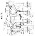
- Fig. 3 is a schematic plan view showing a heating water flow circulation and hot sanitary water supply apparatus in a boiler according to the present invention.
- the heating water flow circulation and hot sanitary water supply apparatus comprises a water-to-water heat exchanger 200 in which sanitary water layers and heating flow layers are alternately multilayer-formed to perform heat exchange between heating flow and sanitary water, and a heating flow diverting unit 300 for diverting a heating flow position so that the heating flow is circulated through heating units, e.g. a radiator, and part of the heating flow is bypassed to the water-to-water heat exchanger 200
- the water-to-water heat exchanger 200 performs heat exchange with a compartment panel 221 having good heat conductivity which is disposed between the heating flow of a high temperature and the sanitary water of a low temperature.
- the water-to-water heat exchanger 200 comprises a casing 210 having a predetermined shape and the compartment panel 221 forming a plurality of layers in the casing 210.
- the compartment panel 221 should form another layer so that the upper layer flow-communicates with the lower layer centering any one layer.
- connections are positioned upward from the casing 210 which are an inlet 242 and an outlet 248 of the heating flow and an inlet 246 and an outlet 244 of the sanitary water.
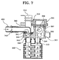
- the heating flow as shown in white arrows in Figs. 4A, 4B, 5, 6 and 7, is introduced to a plurality of heating flow layers 220 and is directed to the outlet 248 of the heating flow.
- the sanitary water is, as shown in black arrows in Figs. 4B, 5, 6 and 7, is introduced to a plurality of sanitary water layers 230 and is directed to the outlet 244 of the sanitary water after heat exchanging.
- a diverting valve 360 of the diverting unit 300 diverts the direction of a heating flow at the instant the flow of the sanitary water is sensed by the flow switch during normal circulation of the heating flow.
- the water-to-water heat exchanger 200 is associated with the diverting unit.
- the diverting unit 320 includes the diverting valve 360, the second heating flow pipe 350, the second sanitary water pipe 340 and the water return pipe 370.
- the diverting valve 360 is interconnectedly installed at the upward of the heating flow outlet 248 of the water-to-water heat exchanger 200 for flow communication, in order to change the direction of the heating flow in the case of circulating the heating flow via heating pipes such as a radiator or using hot water.
- the diverting valve 360 is disposed in a valve box 361 of an approximately cubic shape.
- the second heating flow pipe 350 is associated with a first flange 364 to form an outlet 352 and an inlet 353 of the heating flow.
- the water return pipe 370 is associated with a second flange 365.
- the top of the valve box 361 is opened, in the inside of which a valve chamber 363 is formed.
- the valve chamber 363 is provided with the two-stage ball valve 362.
- the ball valve 362 is rotated at a predetermined angle by a drive shaft 325 eccentriclly installed.
- the ball valve 362 is composed with two through shperes on a vertical shaft, allows inlet and outlet holes of the heating flow of the valve box 361 to be simultaneously opened and closed, and then opens and closes the valve seat 368 of the flange 365.
- the present invention shows a plurality of O-shaped rings, reference numerals of the other except an O-shaped ring 366 are omitted herein.
- the O-shaped rings 366 are interposed between the inlet and outlet of each flange and the connection portions as well as the right and left flange connections of the valve box 361, to thereby prevent the leakage of water.
- the diverting unit 320 is disposed on the diverting valve 360 in order to drive the ball valve 362.
- the diverting unit 320 is connected to the drive shaft 325 with a pin 323 between a motor base 324 of a motor 321 and the ball valve 362.
- a cover member 322 is disposed at the top of the motor base 324 in which the motor 321 is incorporated.
- the first heating flow pipe 310 introduces the heating flow flown out from the main heat exchanger through the inlet 311, of which part is supplied to the second heating pipe and the remaining is dispensed to the first sanitary pipe.
- the first heating flow pipe 310 is provided with an inlet 311 of the heating flow for dispensing the heating flow introduced from the main heat exchanger to the water-to-water heat exchanger 200 and the diverting unit 300, and also is provided with a plurality of outlets 312 and 313 which are respectively connected to the first sanitary water pipe 330 and the second heating flow pipe 350, and includes a pressure switch 314 and a safety valve 315.
- the first sanitary water pipe 330 is composed of two supply paths, one of which is a heating flow inflow path and the other of which is a sanitary water outflow path, as shown in Fig 5.
- the heating flow inflow path has an outlet 331 of the heating flow which is connected to the inlet 242 of the heating flow in the water-to-water heat exchanger
- the sanitary water outflow path has an inlet 332 of the sanitary water which is connected to the outlet 244 of the sanitary water, and an outlet 333 of the hot water which is connected to the hot water supply pipe through a connection 401.
- the second heating flow pipe 350 is positioned between the first heating flow pipe 310 and the diverting valve 360.
- the second heating flow pipe 350 includes a flange 354 in which the outlet 352 and the inlet 353 of the heating flow are formed, and which is connected to the first flange 364.
- an inlet 351 of the heating flow which is connected to the first beating flow pipe 310 to pass the heating flow, and toward the heating flow outlet 352 is provided a connection 102 connected to the pipes of radiators.
- the second sanitary water pipe 340 is provided, as shown in Fig. 7, with a flow switch 344 for generating a signal to sense the flow of cold sanitary water to the water-to-water heat exchanger 200, an outlet 341 of the sanitary water which is connected to the flow switch body 343, and an inlet 342 of the sanitary water associated with a connection 403.
- the water return pipe 370 At one side of the diverting valve 360 is installed the water return pipe 370 to which the heating flow of a low temperature heat-exchanged in the water-to-water heat exchanger 200 is returned to be again supplied to the main heat exchanger 100.
- the water return pipe 370 is provided with a connection 404 associated with an inlet 371 into which the heating flow after circulation through heating unit is introduced, and a flange 372 attached to the flange 365 positioned at the other side of the diverting valve 360 to again supply the heating flow obtained after heat-exchanging to the main heat exchanger 100.
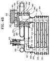
- FIGs. 4A and 4B are sectional views taken along a line A-A of Fig. 3.
- Fig. 4A shows a state that heating flow (indicated in white arrows) during heating is circulated to a heating pipe such as a radiator, and part of the heating flow passes through the water-to-water heat exchanger 200.
- Fig. 4B shows a state that the ball valve 362 is diverted at the moment the sanitary water flow is sensed in the state of Fig. 4A.
- Fig. 4A shows a state that the sanitary water is pre-heated in the water-to-water heat exchanger during heating.
- the ball valve 362 is diverted from the state of Fig. 4A to that of Fig. 4B to block the outlet 352 and the inlet 353 of the second heating flow pipe 350.
- all heating flow passes through the inlet 334 and the outlet 331 of the heating flow of the first sanitary water pipe 330 from the outlet 313 of the first heating flow pipe 310, and is directed form the inlet 242 of the heating flow to the heating flow layers 220 in the water-to-water heat exchanger 200, to thereby perform successive supply of the hot water.
- the sanitary water of the water-to-water heat exchanger 200 is rapidly heated via the sanitary water layers 230, and then the heated hot sanitary water is supplied to hot water taps via the first sanitary water pipe 330.
- the completely-heat-exchanged heating flow flows out toward the water return pipe 370 via the outlet 248 of the heating flow at the heating flow layer 220 and the opened valve seat 368 of the second flange 365 in the diverting valve 360, and then is again supplied to the main heat exchanger 100.
- bypass valve 380 which is opened and closed by differential pressure between the valve box 361 of the diverting valve 360 and the water return pipe 370.
- the bypass valve 380 includes a valve seat 385 formed at the valve box 361, a valve 381 for opening and closing the valve seat 385 formed at the valve box 361 with a valve face 382.
- the valve 381 is provided with springs 383 for elastically maintaining the valve 381.
- the valve 381 which is elastically installed with the springs 383, is closely supported by a support member 384 supported through a hole 386 of the water return pipe 370.
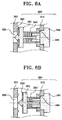
- Figs. 8A and 8B show the operation of the bypass valve 380 according to the present invention.
- Fig. 8A shows that a differential pressure between the valve box 361 and the water return pipe 370 is less than a predetermined pressure when the heating flow is normally circulated.
- Fig. 8B shows that a differential pressure between the valve box 361 and the water return pipe 370 is more than a predetermined pressure.
- the heating flow which is normally circulated through the heating flow pipe blocks or opens/closes an opening path of the heating flow pipe with a temperature control valve (not shown) installed in the heating flow pipe
- a temperature control valve (not shown) installed in the heating flow pipe
- rapid pressure drop occurs at the inlet side of the heating flow pipe, and thus the valve 381 is opened by the hydraulic pressure of the heating flow in the valve chamber 363 to thereby allow the heating flow in the valve chamber 363 to be bypassed to the water return pipe 370.
- Fig. 9 schematically shows, as a whole, the heating flow and hot sanitary water supply apparatus in a boiler according to the present invention.
- the heating flow circulated in water pipes is heated by combustion of oils, gasses, etc, through the main heat exchanger 100.
- the heated heating flow is circulated through the heating flow pipes to heat a radiator.
- part of the heating flow is circulated to pre-heat the sanitary water.
- the heating water flow is repeatedly circulated to heat rooms and at that time the sanitary water is maintained under the preheated condition.
- the hot water can be supplied very soon.
- part of the heating flow during heating is not circulated via the water-to-water heat exchanger 200, and then sanitary water remains cold.
- sanitary water remains cold.
- a certain amount of the cold water, not being pre-heated is initially supplied for a comparatively long time.
- the present invention considering the problem of the conventional hot water supply apparatus in a boiler, circulates the heating flow during heating and bypasses part of the heating flow to pre-heat the sanitary water, thereby even during heating, instantaneously supplying hot water to the bath room, etc.
- the apparatus of the present invention provides a simplified structure of a hot water supply system which is integrated in a multifunctional module by heat-exchange between sanitary water and heating flow, and simplifies complicated construction due to the increase of pipe lines and components such as a connection unit to provide an assembled structure.
- bypass valve which controls the supply of the heating flow is installed between the valve box and the return water pipe to provide a further simplified apparatus.
- a heating water flow circulation and instantaneous hot water supply apparatus is integrated in a single module and thus can reduce a production cost, shorten assembly time and processes, decrease problems due to leakage and installation space, and enhance heat efficiency.
Landscapes
- Engineering & Computer Science (AREA)
- Physics & Mathematics (AREA)
- Thermal Sciences (AREA)
- Chemical & Material Sciences (AREA)
- Combustion & Propulsion (AREA)
- Mechanical Engineering (AREA)
- General Engineering & Computer Science (AREA)
- Domestic Hot-Water Supply Systems And Details Of Heating Systems (AREA)
- Multiple-Way Valves (AREA)
Applications Claiming Priority (2)
| Application Number | Priority Date | Filing Date | Title |
|---|---|---|---|
| KR19980033525 | 1998-08-18 | ||
| KR9833525 | 1998-08-18 |
Publications (2)
| Publication Number | Publication Date |
|---|---|
| EP0981031A2 true EP0981031A2 (de) | 2000-02-23 |
| EP0981031A3 EP0981031A3 (de) | 2002-07-31 |
Family
ID=19547584
Family Applications (1)
| Application Number | Title | Priority Date | Filing Date |
|---|---|---|---|
| EP98124821A Withdrawn EP0981031A3 (de) | 1998-08-18 | 1998-12-30 | Gerät zur Heizwasserumwaltzung und Brauchwasserheizung in einem Kombikessel |
Country Status (1)
| Country | Link |
|---|---|
| EP (1) | EP0981031A3 (de) |
Cited By (5)
| Publication number | Priority date | Publication date | Assignee | Title |
|---|---|---|---|---|
| FR2813950A1 (fr) * | 2000-09-14 | 2002-03-15 | Chaffoteaux Et Maury | Vanne distributrice hydraulique pour systeme de production d'eau chaude de chauffage et d'eau chaude sanitaire |
| EP1650506A1 (de) * | 2004-10-19 | 2006-04-26 | GV STAMPERIE S.p.A. | Boilereinheit für Doppelfunktionsgasboiler und Boiler mit dieser Einheit |
| CN107076461A (zh) * | 2014-11-19 | 2017-08-18 | 庆东纳碧安株式会社 | 具有与水管管道一体化的止回阀的锅炉 |
| CN104500807B (zh) * | 2014-12-16 | 2018-03-27 | 广东万和热能科技有限公司 | 阀体及具有其的燃气采暖热水炉 |
| CN115751432A (zh) * | 2022-11-07 | 2023-03-07 | 沧州青尚环保科技有限公司 | 一种室内暖通处理系统 |
Family Cites Families (7)
| Publication number | Priority date | Publication date | Assignee | Title |
|---|---|---|---|---|
| FR2595454B1 (fr) * | 1986-03-07 | 1989-01-13 | Elettro Termica Sud Spa | Chaudiere a gaz |
| AT398857B (de) * | 1991-10-31 | 1995-02-27 | Vaillant Gmbh | Verfahren zur steuerung einer heizeinrichtung und heizeinrichtung zur durchführung des verfahrens |
| JP3025595B2 (ja) * | 1993-03-05 | 2000-03-27 | 東京瓦斯株式会社 | 給湯暖房機 |
| IT230482Y1 (it) * | 1993-11-10 | 1999-06-07 | Beretta A Ing Spa | Gruppo idraulico estremamente compatto per caldaie murali a gas |
| IT1284431B1 (it) * | 1996-03-22 | 1998-05-21 | Fugas Srl | Gruppo idraulico con pompa integrata per impianti misti di riscaldamento e acqua sanitaria |
| DE19632605A1 (de) * | 1996-08-13 | 1998-02-19 | Wilo Gmbh | Hydraulikbaugruppe für eine kombinierte Heizwasser- und Sanitärwasseranlage |
| EP0916901A1 (de) * | 1997-11-11 | 1999-05-19 | IABER S.p.A. | Gerät zum Unterbinden von Kesselsteinbildung für Gasheizkessel |
-
1998
- 1998-12-30 EP EP98124821A patent/EP0981031A3/de not_active Withdrawn
Non-Patent Citations (1)
| Title |
|---|
| None |
Cited By (9)
| Publication number | Priority date | Publication date | Assignee | Title |
|---|---|---|---|---|
| FR2813950A1 (fr) * | 2000-09-14 | 2002-03-15 | Chaffoteaux Et Maury | Vanne distributrice hydraulique pour systeme de production d'eau chaude de chauffage et d'eau chaude sanitaire |
| EP1188991A1 (de) * | 2000-09-14 | 2002-03-20 | Chaffoteaux Et Maury | Hydraulisches Verteilerventil für kombinierte Heizungsanlage |
| EP1650506A1 (de) * | 2004-10-19 | 2006-04-26 | GV STAMPERIE S.p.A. | Boilereinheit für Doppelfunktionsgasboiler und Boiler mit dieser Einheit |
| CN107076461A (zh) * | 2014-11-19 | 2017-08-18 | 庆东纳碧安株式会社 | 具有与水管管道一体化的止回阀的锅炉 |
| RU2676172C2 (ru) * | 2014-11-19 | 2018-12-26 | Киунгдонг Навиен Ко., Лтд. | Котел, имеющий обратный клапан, встроенный в трубопровод для воды |
| CN107076461B (zh) * | 2014-11-19 | 2020-01-31 | 庆东纳碧安株式会社 | 具有与水管管道一体化的止回阀的锅炉 |
| CN104500807B (zh) * | 2014-12-16 | 2018-03-27 | 广东万和热能科技有限公司 | 阀体及具有其的燃气采暖热水炉 |
| CN115751432A (zh) * | 2022-11-07 | 2023-03-07 | 沧州青尚环保科技有限公司 | 一种室内暖通处理系统 |
| CN115751432B (zh) * | 2022-11-07 | 2023-05-16 | 沧州青尚环保科技有限公司 | 一种室内暖通处理系统 |
Also Published As
| Publication number | Publication date |
|---|---|
| EP0981031A3 (de) | 2002-07-31 |
Similar Documents
| Publication | Publication Date | Title |
|---|---|---|
| JP2009092304A (ja) | 貯湯式温水器 | |
| US2814279A (en) | Dual water heating systems | |
| US10337762B2 (en) | Heat exchanger and heat source device | |
| US3254839A (en) | Unitary heating system | |
| JP2017198414A (ja) | 給湯空調システム | |
| JP3869804B2 (ja) | ヒートポンプ式給湯暖房装置 | |
| JP4436771B2 (ja) | 熱交換器、ヒートポンプ式給湯装置及びヒートポンプ式給湯暖房装置 | |
| EP0652408A1 (de) | Sehr kompakte hydraulische Baugruppe für gasbeheizte Wandkessel | |
| KR100342131B1 (ko) | 보일러의 난방/급탕수제어장치 | |
| KR100301105B1 (ko) | 보일러급탕장치 | |
| KR100342132B1 (ko) | 난방 및 온수제어장치 | |
| JP2004144381A (ja) | 貯湯式給湯装置の湯水混合弁 | |
| JP4867273B2 (ja) | 給湯装置 | |
| JP2018091504A (ja) | 蓄熱システム | |
| JP7526694B2 (ja) | 給湯装置 | |
| JPH11108442A5 (de) | ||
| JP4711129B2 (ja) | 液体加熱装置 | |
| JP2008082633A (ja) | 給湯装置とプレート式熱交換器 | |
| JP4126814B2 (ja) | 温水分岐ユニット | |
| JP3554878B2 (ja) | 温水供給装置 | |
| JP3859829B2 (ja) | 一缶二水路風呂給湯器 | |
| JPH048675B2 (de) | ||
| EP0687871B1 (de) | Heizkessel, aus mehreren Räumen bestehend | |
| JPS5945902B2 (ja) | 循環給湯風呂釜 | |
| JP2015068618A (ja) | 給湯暖房装置 |
Legal Events
| Date | Code | Title | Description |
|---|---|---|---|
| PUAI | Public reference made under article 153(3) epc to a published international application that has entered the european phase |
Free format text: ORIGINAL CODE: 0009012 |
|
| 17P | Request for examination filed |
Effective date: 19990113 |
|
| AK | Designated contracting states |
Kind code of ref document: A2 Designated state(s): AT BE CH CY DE DK ES FI FR GB GR IE IT LI LU MC NL PT SE |
|
| AX | Request for extension of the european patent |
Free format text: AL;LT;LV;MK;RO;SI |
|
| PUAL | Search report despatched |
Free format text: ORIGINAL CODE: 0009013 |
|
| AK | Designated contracting states |
Kind code of ref document: A3 Designated state(s): AT BE CH CY DE DK ES FI FR GB GR IE IT LI LU MC NL PT SE |
|
| AX | Request for extension of the european patent |
Free format text: AL;LT;LV;MK;RO;SI |
|
| RIC1 | Information provided on ipc code assigned before grant |
Free format text: 7F 24H 1/52 A, 7F 24D 3/08 B, 7F 24H 9/14 B, 7F 24H 9/20 B |
|
| AKX | Designation fees paid |
Designated state(s): DE ES FR GB IT NL |
|
| STAA | Information on the status of an ep patent application or granted ep patent |
Free format text: STATUS: THE APPLICATION IS DEEMED TO BE WITHDRAWN |
|
| 18D | Application deemed to be withdrawn |
Effective date: 20040701 |