EP0652408A1 - Sehr kompakte hydraulische Baugruppe für gasbeheizte Wandkessel - Google Patents
Sehr kompakte hydraulische Baugruppe für gasbeheizte Wandkessel Download PDFInfo
- Publication number
- EP0652408A1 EP0652408A1 EP94117592A EP94117592A EP0652408A1 EP 0652408 A1 EP0652408 A1 EP 0652408A1 EP 94117592 A EP94117592 A EP 94117592A EP 94117592 A EP94117592 A EP 94117592A EP 0652408 A1 EP0652408 A1 EP 0652408A1
- Authority
- EP
- European Patent Office
- Prior art keywords
- heat exchanger
- manostat
- way valve
- hydraulic assembly
- water
- Prior art date
- Legal status (The legal status is an assumption and is not a legal conclusion. Google has not performed a legal analysis and makes no representation as to the accuracy of the status listed.)
- Granted
Links
Images


Classifications
-
- F—MECHANICAL ENGINEERING; LIGHTING; HEATING; WEAPONS; BLASTING
- F24—HEATING; RANGES; VENTILATING
- F24H—FLUID HEATERS, e.g. WATER OR AIR HEATERS, HAVING HEAT-GENERATING MEANS, e.g. HEAT PUMPS, IN GENERAL
- F24H9/00—Details
- F24H9/14—Arrangements for connecting different sections, e.g. in water heaters
- F24H9/142—Connecting hydraulic components
- F24H9/144—Valve seats, piping and heat exchanger connections integrated into a one-piece hydraulic unit
-
- F—MECHANICAL ENGINEERING; LIGHTING; HEATING; WEAPONS; BLASTING
- F24—HEATING; RANGES; VENTILATING
- F24H—FLUID HEATERS, e.g. WATER OR AIR HEATERS, HAVING HEAT-GENERATING MEANS, e.g. HEAT PUMPS, IN GENERAL
- F24H9/00—Details
- F24H9/14—Arrangements for connecting different sections, e.g. in water heaters
Definitions
- the present invention generally relates to wall gas-fired boilers and, more particularly, to an improved hydraulic assembly to be used in wall gas-fired boilers for the production of hot water for sanitary purposes and for environmental heating purposes.
- the thermal carrier transports the heat directly to the heating system comprising, for example radiating elements, and indirectly to the water circuit for sanitary purposes through a second water-water heat exchanger in which the heat exchange with the sanitary water occurs.
- a plurality of valves and interconnected control means are necessary for the correct and safe operation of such boilers.
- the aim of the present invention is to overcome the above disadvantages and limitations by providing a hydraulic connection among the valves and/or the various control means which minimizes the overal dimensions and the costs while maintaining a good assembly facility.
- the object of the present invention is to minimize the overal dimensions of the interconnections by providing a very compact hydraulic assembly, which is easy to be mounted and maintained and in which the connection of the valves and the various control means is obtained without the use of intermediate pipes.
- the very compact hydraulic assembly for wall gas-fired boilers of the type comprising two separate hydraulic circuits, i.e. a main circuit for the heating system and a secondary circuit for heating the sanitary water, a gas burner, a main gas-water heat exchanger, a circulation pump, a secondary water-water plate-type heat exchanger, a three-way valve for switching the hot water flow coming from the main heat exchanger to the secondary heat exchanger and control means, such as a manostat, a by-pass valve, a safety valve and a differential manostat is characterized according to the present invention in that it comprises a single block provided with seats for:
- control of said three-way valve for switching the hot water flow in the secondary heat exchanger is obtained by an external lever operated by said differential manostat.
- the hydraulic assembly has the three-way valve located in the return pipe of the main circuit in order to avoid undesirable water hammering effects.
- said differential manostat comprises a venturi, a connecting element to the plate-type heat exchanger and a connecting element to the single block, integrally formed therein.
- the hydraulic assembly is provided with a connector for the connection to a hydraulic accumulator.
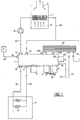
- Fig. 1 diagrammatically shows the gas-fired boiler together with the hydraulic assembly according to the present invention.
- the wall gas-fired boilers herein contemplated comprise a main circuit for the flow of the hot water intended for the heating system, a secondary circuit for the flow of the hot water intended for sanitary purposes, a main heat exchanger 7 connected to the main circuit, a secondary heat exchanger 10 connected to the secondary circuit, a three-way valve 4, a differential manostat 3 for controlling the three-way valve 4, a by-pass valve 5, a safety manostat 2, a safety valve and a plurality of connectors for connecting external pipes of the main circuit and the secondary circuit.
- the main part of the hydraulic assembly according to the present invention is formed by a single block 1 which has been designed for receiving all the main components of the boiler hydraulic circuit.
- the differential manostat 3 for controlling the three-way valve 4, the safety manostat 2, the by-pass valve 5 and the connectors 12,13,14A, 15A,16,17,18 and 19 to which the return pipe 24 of the main circuit, the delivery pipe 25 of the main circuit, the inlet connector 14B of the plate-type secondary heat exchager 10, the outlet connector 15B of the latter, the return pipe 29 of the heating circuit, the delivery pipe 28 of the heating circuit, the connecting pipe 20 to the hydraulic accumulator 21 and the delivery pipe 26 of the sanitary water circuit are connected.
- the heating circuit 11 provided with radiating elements R, the hydraulic accumulator 21, the plate-type heat exchanger 10, the delivery and return pipes 25 and 24 of the main circuit and the delivery and return pipes 27 and 26 of the secondary circuit for heating the sanitary water are connected.
- the differential manostat 3 controls the three-way valve 4 by means of an external lever 30 which permits an easy regulation and maintenance thereof.
- the circulation pump 6 in this case can be located in the return pipe 29 of the heating circuit, what permits undesirable water hammering effects to be avoided.
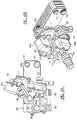
- Fig. 2A diagrammatically shows the interconnections in the inner portion of the single block 1, here shown in dotted lines.
- the conduct 31 interconnects the three-way valve 4 and the plate-type secondary heat exchanger 10, the conducts 39,40 interconnect the safety manostat 2 provided with electric switch 38 and the three-way valve 4, the conduct 37 provided with the by-pass valve 5 interconnects the differential manostat 3 to the three-way valve 4.
- a lever 30 (outside the single block 1) with pivot F is provided for transmitting the control movement given by the differential manostat 3 to the three-way valve 4.
- a microswitch 32 is operated by the manostat 3 and the conducts 33,35 and 36 interconnect the differential manostat 3.
- 41 is the by-pass valve.
- Fig. 2A the condition of heating only is shown since, because no flow passes in the pipes 26 and 27 of the sanitary water, the differential manostat 3 remains in a lowered position because there is pressure balance between the upper chamber and the lower chamber thereof and the spring 42 assures therefore the lowered steady position of the lever.
- the lever 30 maintains the three-way valve 4 closed and this position is assured by the preloaded spring 44 located within said valve 4.
- the single active circuit is therefore the heating circuit only wherein the water, after being heated in the main heat exchanger 7, flows through the pipe 25, enters the conduct 31 but does not flow therein, flows in the delivery pipe 28, reaches the radiating elements R (not shown in Figure) and then returns through the return pipe 29.
- the water Once the water is come within the hydraulic assembly 1, it flows through the three-way valve 4 which switches then it in the return pipe 24 to which the circulation pump 6 is connected.
- the safety manostat 2 is connected to the three-way valve 4 by means of the pipes 39 and 40 in order to confirm the presence of pressurized water in the main circuit; on the contrary (lack of water in the main circuit and/or in the not operated circulation pump), a microswitch 38 connected thereto by menas of the stem 47, disables the pump 6 and the burners 8.
- Fig. 2B is represented the condition in which the sanitary hot water is required.
- This requirement causes a sanitary water flow through the pipes 26 and 35 in which the venturi 34 causes a vacuum in the upper chamber of the manostat 3 through the conduct 46; this vacuum causes the stem 43 of the manostat 3 to lift and to simultaneously change the condition of the microswitch 32 and the control lever 30 to rotate.
- the lever 30 switches the three-way valve 4 so as to connect the sanitary water circuit and to disconnect the heating circuit by closing the return pipe 29 and permits the flow of the water through the conduct 31.
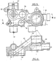
- the single block 1 is represented in a perspective view, in elevational view and in cross section, respectively.
- this single block is provided with the various seats for housing, mounting and connecting the various components and pipes of the boiler.
- the preassembling operation of the various components is usually carried out in the shop so as to form, as better shown in Fig. 4B, a very compact structure which is then integrated into the boiler.
- Fig. 3 shows the single block 1 provided with the seat 50 for the connector of the plate-type heat exchanger 10 of Fig. 2A, the seat 51 for the by-pass valve 5, the seat 52 for the connector of the pipe 24 of Fig. 2A, the seat 53 for the connection of the differential manostat 3 of Fig, 2A, the seat 54 for the connector of the pipe 25 of Fig. 2A, the seat 55 for the safety manostat 2 of Fig. 2A to which the safety switch 38 of Fig. 2A is usually connected, the seat 56 for facilitating the access of the wrench necessary for connecting the plate-type heat exchanger 10, the seat 57 for the three-way valve 4 of fig. 2A, the seat 58 for a safety valve, the seat 59 for the pipe 28 of Fig. 2A, the seat 60 for a flowmeter, the seat 61 for the pipe 29 of Fig. 2A and finally the seat 62 for the pipe 20 of Fig. 2A.
- the differential manostat 3 is designed so as to contain the venturi 34 and a tube for the connection to the pipe 26 of Fig. 2A, said venturi 34 and said tube being integrally formed in the differential manostat.
- Fig. 6 there are shown in cross section some internal conducts interconnecting the various above mentioned seats; for example the conduct 63 interconnecting the seats 51,55,58 and 61 of Fig. 5.
- Fig, 4A is a front view of all the hydraulic assembly obtained after that all the necessary components have been mounted in the single block, wherein all the seats cited in the description of Fig. 3 are shown with the exception of the seat 64 usually present in the differential manostat 3 in turn integrated in the seat 53 of Fig .3.
- Fig. 4B shows in a perspective view the hydraulic assembly.
- two electric switches 63A and 63B corresponding to the switches 32 and 38, respectively shown in Fig. 2A and the external lever 65 by means of which the differential manostat 3 controls the switching operation of the three-way valve 4.
- the lever corresponds to the lever 30 in Figure 2A and in Fig. 1.
Landscapes
- Engineering & Computer Science (AREA)
- Physics & Mathematics (AREA)
- Thermal Sciences (AREA)
- Chemical & Material Sciences (AREA)
- Combustion & Propulsion (AREA)
- Mechanical Engineering (AREA)
- General Engineering & Computer Science (AREA)
- Multiple-Way Valves (AREA)
- Feeding And Controlling Fuel (AREA)
- Steam Or Hot-Water Central Heating Systems (AREA)
Applications Claiming Priority (2)
| Application Number | Priority Date | Filing Date | Title |
|---|---|---|---|
| ITMI930870U | 1993-11-10 | ||
| ITMI930870 IT230482Y1 (it) | 1993-11-10 | 1993-11-10 | Gruppo idraulico estremamente compatto per caldaie murali a gas |
Publications (2)
| Publication Number | Publication Date |
|---|---|
| EP0652408A1 true EP0652408A1 (de) | 1995-05-10 |
| EP0652408B1 EP0652408B1 (de) | 1998-04-08 |
Family
ID=11365972
Family Applications (1)
| Application Number | Title | Priority Date | Filing Date |
|---|---|---|---|
| EP19940117592 Expired - Lifetime EP0652408B1 (de) | 1993-11-10 | 1994-11-08 | Sehr kompakte hydraulische Baugruppe für gasbeheizte Wandkessel |
Country Status (3)
| Country | Link |
|---|---|
| EP (1) | EP0652408B1 (de) |
| ES (1) | ES2117189T3 (de) |
| IT (1) | IT230482Y1 (de) |
Cited By (12)
| Publication number | Priority date | Publication date | Assignee | Title |
|---|---|---|---|---|
| EP0797057A2 (de) * | 1996-03-22 | 1997-09-24 | FUGAS s.r.l. | Ventileinheit mit integrierter Pumpe für kombiniertem Kessel |
| FR2755752A1 (fr) * | 1996-11-08 | 1998-05-15 | Aries | Module hydraulique pour installation de chauffage central et de production d'eau chaude, et chaudiere equipee d'un tel module |
| EP0825387A3 (de) * | 1996-08-13 | 1999-03-17 | WILO GmbH | Hydraulikbaugruppe für eine kombinierte Heizwasser- und Sanitärwasseranlage |
| EP0994311A2 (de) | 1998-10-14 | 2000-04-19 | FUGAS s.r.l. | Hydraulische Baugruppe für Heizungs-und Heisswasseranlagen , mit einem Heisswasserspeicher |
| EP1026456A1 (de) | 1999-02-03 | 2000-08-09 | IABER S.p.A. | Hydraulische Verteilergruppe |
| EP0981031A3 (de) * | 1998-08-18 | 2002-07-31 | ALCO Corporation of Namdong Industrial Area 156BL/10LT | Gerät zur Heizwasserumwaltzung und Brauchwasserheizung in einem Kombikessel |
| EP1130342A3 (de) * | 2000-02-21 | 2003-04-02 | Grundfos A/S | Baueinheit für eine Kompaktheizungsanlage |
| NL1021594C2 (nl) | 2002-10-07 | 2004-04-08 | Nefit Buderus B V | Verwarmingstoestel. |
| EP1650506A1 (de) * | 2004-10-19 | 2006-04-26 | GV STAMPERIE S.p.A. | Boilereinheit für Doppelfunktionsgasboiler und Boiler mit dieser Einheit |
| EP1845314A1 (de) * | 2006-04-14 | 2007-10-17 | Fugas Spa | Hydraulikbaugruppe für den Rücklauf eines Wandkessels |
| EP2942583A1 (de) * | 2014-05-06 | 2015-11-11 | O.T.M.A. S.N.C. di Spaggiari & C. | Blockartiger grundkörper für eine hydraulikbaugruppe zur verwendung in einem wandmontierten boiler |
| EP2484989A4 (de) * | 2009-09-28 | 2016-08-31 | Kyungdong Navien Co Ltd | Heisswasserversorgungs-wärmetauscher mit einem mischventil und adapter mit eingebautem mischventil |
Citations (1)
| Publication number | Priority date | Publication date | Assignee | Title |
|---|---|---|---|---|
| EP0236235A1 (de) * | 1986-03-07 | 1987-09-09 | ELETTRO TERMICA SUD S.p.A. | Gaskessel |
-
1993
- 1993-11-10 IT ITMI930870 patent/IT230482Y1/it active IP Right Grant
-
1994
- 1994-11-08 EP EP19940117592 patent/EP0652408B1/de not_active Expired - Lifetime
- 1994-11-08 ES ES94117592T patent/ES2117189T3/es not_active Expired - Lifetime
Patent Citations (1)
| Publication number | Priority date | Publication date | Assignee | Title |
|---|---|---|---|---|
| EP0236235A1 (de) * | 1986-03-07 | 1987-09-09 | ELETTRO TERMICA SUD S.p.A. | Gaskessel |
Cited By (14)
| Publication number | Priority date | Publication date | Assignee | Title |
|---|---|---|---|---|
| EP0797057A3 (de) * | 1996-03-22 | 1998-10-14 | FUGAS s.r.l. | Ventileinheit mit integrierter Pumpe für kombiniertem Kessel |
| EP0797057A2 (de) * | 1996-03-22 | 1997-09-24 | FUGAS s.r.l. | Ventileinheit mit integrierter Pumpe für kombiniertem Kessel |
| EP0825387A3 (de) * | 1996-08-13 | 1999-03-17 | WILO GmbH | Hydraulikbaugruppe für eine kombinierte Heizwasser- und Sanitärwasseranlage |
| FR2755752A1 (fr) * | 1996-11-08 | 1998-05-15 | Aries | Module hydraulique pour installation de chauffage central et de production d'eau chaude, et chaudiere equipee d'un tel module |
| WO1998021529A1 (fr) * | 1996-11-08 | 1998-05-22 | Vergne Innovation | Module hydraulique pour installation de chauffage central |
| EP0981031A3 (de) * | 1998-08-18 | 2002-07-31 | ALCO Corporation of Namdong Industrial Area 156BL/10LT | Gerät zur Heizwasserumwaltzung und Brauchwasserheizung in einem Kombikessel |
| EP0994311A2 (de) | 1998-10-14 | 2000-04-19 | FUGAS s.r.l. | Hydraulische Baugruppe für Heizungs-und Heisswasseranlagen , mit einem Heisswasserspeicher |
| EP1026456A1 (de) | 1999-02-03 | 2000-08-09 | IABER S.p.A. | Hydraulische Verteilergruppe |
| EP1130342A3 (de) * | 2000-02-21 | 2003-04-02 | Grundfos A/S | Baueinheit für eine Kompaktheizungsanlage |
| NL1021594C2 (nl) | 2002-10-07 | 2004-04-08 | Nefit Buderus B V | Verwarmingstoestel. |
| EP1650506A1 (de) * | 2004-10-19 | 2006-04-26 | GV STAMPERIE S.p.A. | Boilereinheit für Doppelfunktionsgasboiler und Boiler mit dieser Einheit |
| EP1845314A1 (de) * | 2006-04-14 | 2007-10-17 | Fugas Spa | Hydraulikbaugruppe für den Rücklauf eines Wandkessels |
| EP2484989A4 (de) * | 2009-09-28 | 2016-08-31 | Kyungdong Navien Co Ltd | Heisswasserversorgungs-wärmetauscher mit einem mischventil und adapter mit eingebautem mischventil |
| EP2942583A1 (de) * | 2014-05-06 | 2015-11-11 | O.T.M.A. S.N.C. di Spaggiari & C. | Blockartiger grundkörper für eine hydraulikbaugruppe zur verwendung in einem wandmontierten boiler |
Also Published As
| Publication number | Publication date |
|---|---|
| ITMI930870U1 (it) | 1995-05-10 |
| EP0652408B1 (de) | 1998-04-08 |
| IT230482Y1 (it) | 1999-06-07 |
| ES2117189T3 (es) | 1998-08-01 |
| ITMI930870V0 (it) | 1993-11-10 |
Similar Documents
| Publication | Publication Date | Title |
|---|---|---|
| EP0652408A1 (de) | Sehr kompakte hydraulische Baugruppe für gasbeheizte Wandkessel | |
| US4756475A (en) | Gas-fired boiler | |
| KR100596161B1 (ko) | 분리형 이중 열교환식 급탕 보일러 | |
| EP0797057B1 (de) | Ventileinheit mit integrierter Pumpe für kombinierten Kessel zur Erzeugung von Heizwärme und Warmwasser | |
| US6161567A (en) | Single chamber water circulator | |
| EP0568122B1 (de) | Ventilanordnung für Anlagen, die sowohl für Heizungs- als auch für Haushaltsheisswasser vorgesehen ist | |
| EP0244915A2 (de) | Integrierte Wasserleitungen für Wassererhitzer für Heizung und Brauchwasser | |
| US5287567A (en) | Hydraulic isolation manifold | |
| KR100543254B1 (ko) | 온수·위생수겸용설비용수압식어셈블리 | |
| EP0693658A1 (de) | Verbesserte Ventilanordnung für Anlagen, die sowohl für Heizungs- als auch für Haushaltsheisswasser vorgesehen ist | |
| KR102029825B1 (ko) | 열교환기가 구비되는 지역난방용 배관모듈 | |
| EP0614061A1 (de) | Steuereinrichtung für Plattenwärmetauscher und entsprechender Wärmetauscher | |
| EP1065447A2 (de) | Verteiler für thermisches System mit Zwangsumlauf | |
| EP3680574A1 (de) | Hydraulikbaugruppe | |
| KR20010073820A (ko) | 보일러의 난방/급탕수제어장치 | |
| EP0519030B1 (de) | Gaserhitzter wasserkessel | |
| EP1546611B1 (de) | Verteiler für zentralheizungssysteme | |
| WO1991011664A1 (en) | Water heating arrangement | |
| EP0981031A2 (de) | Gerät zur Heizwasserumwaltzung und Brauchwasserheizung in einem Kombikessel | |
| EP0509611B1 (de) | Kombinierter Kessel mit Wärmetauscher mit Einbaupumpen | |
| GB2241564A (en) | Domestic water heating boilers | |
| EP0976989B1 (de) | Wasserkreislauf eines kombinierten Gaswandkessels | |
| EP4361523A1 (de) | Brennwertkessel mit brenner und speicher für hybridanlagen mit wärmepumpe | |
| KR20010039181A (ko) | 난방 및 온수제어장치 | |
| EP4058737B1 (de) | Warmwasserbereiteranordnung mit einer ventilbaugruppe |
Legal Events
| Date | Code | Title | Description |
|---|---|---|---|
| PUAI | Public reference made under article 153(3) epc to a published international application that has entered the european phase |
Free format text: ORIGINAL CODE: 0009012 |
|
| AK | Designated contracting states |
Kind code of ref document: A1 Designated state(s): ES FR GB NL |
|
| 17P | Request for examination filed |
Effective date: 19950724 |
|
| 17Q | First examination report despatched |
Effective date: 19951220 |
|
| GRAG | Despatch of communication of intention to grant |
Free format text: ORIGINAL CODE: EPIDOS AGRA |
|
| GRAG | Despatch of communication of intention to grant |
Free format text: ORIGINAL CODE: EPIDOS AGRA |
|
| GRAH | Despatch of communication of intention to grant a patent |
Free format text: ORIGINAL CODE: EPIDOS IGRA |
|
| GRAH | Despatch of communication of intention to grant a patent |
Free format text: ORIGINAL CODE: EPIDOS IGRA |
|
| GRAA | (expected) grant |
Free format text: ORIGINAL CODE: 0009210 |
|
| AK | Designated contracting states |
Kind code of ref document: B1 Designated state(s): ES FR GB NL |
|
| ET | Fr: translation filed | ||
| RAP2 | Party data changed (patent owner data changed or rights of a patent transferred) |
Owner name: IABER S.P.A. |
|
| REG | Reference to a national code |
Ref country code: ES Ref legal event code: FG2A Ref document number: 2117189 Country of ref document: ES Kind code of ref document: T3 |
|
| NLT2 | Nl: modifications (of names), taken from the european patent patent bulletin |
Owner name: IABER S.P.A. |
|
| NLT1 | Nl: modifications of names registered in virtue of documents presented to the patent office pursuant to art. 16 a, paragraph 1 |
Owner name: IABER S.P.A. |
|
| PLBE | No opposition filed within time limit |
Free format text: ORIGINAL CODE: 0009261 |
|
| STAA | Information on the status of an ep patent application or granted ep patent |
Free format text: STATUS: NO OPPOSITION FILED WITHIN TIME LIMIT |
|
| 26N | No opposition filed | ||
| REG | Reference to a national code |
Ref country code: GB Ref legal event code: IF02 |
|
| PGFP | Annual fee paid to national office [announced via postgrant information from national office to epo] |
Ref country code: ES Payment date: 20020918 Year of fee payment: 9 |
|
| PGFP | Annual fee paid to national office [announced via postgrant information from national office to epo] |
Ref country code: GB Payment date: 20020923 Year of fee payment: 9 |
|
| PGFP | Annual fee paid to national office [announced via postgrant information from national office to epo] |
Ref country code: FR Payment date: 20020927 Year of fee payment: 9 |
|
| PGFP | Annual fee paid to national office [announced via postgrant information from national office to epo] |
Ref country code: NL Payment date: 20021130 Year of fee payment: 9 |
|
| PG25 | Lapsed in a contracting state [announced via postgrant information from national office to epo] |
Ref country code: GB Free format text: LAPSE BECAUSE OF NON-PAYMENT OF DUE FEES Effective date: 20031108 |
|
| PG25 | Lapsed in a contracting state [announced via postgrant information from national office to epo] |
Ref country code: ES Free format text: LAPSE BECAUSE OF NON-PAYMENT OF DUE FEES Effective date: 20031110 |
|
| PG25 | Lapsed in a contracting state [announced via postgrant information from national office to epo] |
Ref country code: NL Free format text: LAPSE BECAUSE OF NON-PAYMENT OF DUE FEES Effective date: 20040601 |
|
| GBPC | Gb: european patent ceased through non-payment of renewal fee |
Effective date: 20031108 |
|
| PG25 | Lapsed in a contracting state [announced via postgrant information from national office to epo] |
Ref country code: FR Free format text: LAPSE BECAUSE OF NON-PAYMENT OF DUE FEES Effective date: 20040730 |
|
| NLV4 | Nl: lapsed or anulled due to non-payment of the annual fee |
Effective date: 20040601 |
|
| REG | Reference to a national code |
Ref country code: FR Ref legal event code: ST |
|
| REG | Reference to a national code |
Ref country code: ES Ref legal event code: FD2A Effective date: 20031110 |