EP0797057A2 - Ventileinheit mit integrierter Pumpe für kombiniertem Kessel - Google Patents
Ventileinheit mit integrierter Pumpe für kombiniertem Kessel Download PDFInfo
- Publication number
- EP0797057A2 EP0797057A2 EP96110213A EP96110213A EP0797057A2 EP 0797057 A2 EP0797057 A2 EP 0797057A2 EP 96110213 A EP96110213 A EP 96110213A EP 96110213 A EP96110213 A EP 96110213A EP 0797057 A2 EP0797057 A2 EP 0797057A2
- Authority
- EP
- European Patent Office
- Prior art keywords
- assembly
- water
- sub
- valve
- fitting
- Prior art date
- Legal status (The legal status is an assumption and is not a legal conclusion. Google has not performed a legal analysis and makes no representation as to the accuracy of the status listed.)
- Granted
Links
- XLYOFNOQVPJJNP-UHFFFAOYSA-N water Substances O XLYOFNOQVPJJNP-UHFFFAOYSA-N 0.000 title claims abstract description 78
- 238000010438 heat treatment Methods 0.000 title claims abstract description 13
- 239000002131 composite material Substances 0.000 claims abstract description 15
- 239000000463 material Substances 0.000 claims abstract description 15
- 239000004033 plastic Substances 0.000 claims abstract description 13
- 238000000429 assembly Methods 0.000 claims abstract description 11
- 239000008236 heating water Substances 0.000 claims abstract description 11
- 239000002184 metal Substances 0.000 claims description 22
- 229910001369 Brass Inorganic materials 0.000 claims description 6
- 239000010951 brass Substances 0.000 claims description 5
- 229920000642 polymer Polymers 0.000 claims description 3
- 238000013022 venting Methods 0.000 claims description 3
- 239000004677 Nylon Substances 0.000 claims description 2
- 229920013632 Ryton Polymers 0.000 claims description 2
- 239000004736 Ryton® Substances 0.000 claims description 2
- 239000003365 glass fiber Substances 0.000 claims description 2
- 229920001778 nylon Polymers 0.000 claims description 2
- 229920001169 thermoplastic Polymers 0.000 claims description 2
- 238000010276 construction Methods 0.000 description 8
- 230000008901 benefit Effects 0.000 description 2
- 238000009434 installation Methods 0.000 description 2
- 238000012423 maintenance Methods 0.000 description 2
- 238000004519 manufacturing process Methods 0.000 description 2
- 230000009467 reduction Effects 0.000 description 2
- 238000007789 sealing Methods 0.000 description 2
- 230000000712 assembly Effects 0.000 description 1
- 230000000903 blocking effect Effects 0.000 description 1
- 230000008878 coupling Effects 0.000 description 1
- 238000010168 coupling process Methods 0.000 description 1
- 238000005859 coupling reaction Methods 0.000 description 1
- 230000001419 dependent effect Effects 0.000 description 1
- 230000000694 effects Effects 0.000 description 1
- 239000000835 fiber Substances 0.000 description 1
- 238000010304 firing Methods 0.000 description 1
- 238000003780 insertion Methods 0.000 description 1
- 230000037431 insertion Effects 0.000 description 1
- 238000012986 modification Methods 0.000 description 1
- 230000004048 modification Effects 0.000 description 1
- 238000013021 overheating Methods 0.000 description 1
- 239000000523 sample Substances 0.000 description 1
- 230000007480 spreading Effects 0.000 description 1
- 239000000126 substance Substances 0.000 description 1
- 239000004416 thermosoftening plastic Substances 0.000 description 1
Images


Classifications
-
- F—MECHANICAL ENGINEERING; LIGHTING; HEATING; WEAPONS; BLASTING
- F24—HEATING; RANGES; VENTILATING
- F24D—DOMESTIC- OR SPACE-HEATING SYSTEMS, e.g. CENTRAL HEATING SYSTEMS; DOMESTIC HOT-WATER SUPPLY SYSTEMS; ELEMENTS OR COMPONENTS THEREFOR
- F24D3/00—Hot-water central heating systems
- F24D3/08—Hot-water central heating systems in combination with systems for domestic hot-water supply
-
- F—MECHANICAL ENGINEERING; LIGHTING; HEATING; WEAPONS; BLASTING
- F24—HEATING; RANGES; VENTILATING
- F24H—FLUID HEATERS, e.g. WATER OR AIR HEATERS, HAVING HEAT-GENERATING MEANS, e.g. HEAT PUMPS, IN GENERAL
- F24H9/00—Details
- F24H9/12—Arrangements for connecting heaters to circulation pipes
- F24H9/13—Arrangements for connecting heaters to circulation pipes for water heaters
-
- F—MECHANICAL ENGINEERING; LIGHTING; HEATING; WEAPONS; BLASTING
- F24—HEATING; RANGES; VENTILATING
- F24H—FLUID HEATERS, e.g. WATER OR AIR HEATERS, HAVING HEAT-GENERATING MEANS, e.g. HEAT PUMPS, IN GENERAL
- F24H9/00—Details
- F24H9/14—Arrangements for connecting different sections, e.g. in water heaters
- F24H9/142—Connecting hydraulic components
Definitions
- the present invention concerns a valve assembly adapted for being used in combined plants for providing both heating and sanitary hot water, i.e. residential plants wherein the same heat source, particularly a wall-mounted gas-fired boiler, is used for heating both the water for the heat spreading elements (radiators) for heating the rooms, and the sanitary or domestic hot water for various purposes.
- the same heat source particularly a wall-mounted gas-fired boiler
- EP-A-0 568 122 in the name of the same applicant discloses a valve assembly formed by two sub-assemblies or valve units for a combined plants for heating and sanitary hot water comprising a gas burner, a (main) gas/water heat exchanger, a water/water heat exchanger connectable through a three-way valve into the heating water circuit, at least a radiator and a pump for circulating the heating water.
- a pipe fitting for the connection with the main heat exchanger In the body of a first unit of such assembly there are formed the three-way valve, a pipe fitting for the connection with the main heat exchanger, a fitting for the connection with the radiators, an outlet fitting for the domestic water, two pipe fittings for the connection with the water/water heat exchanger, a manostat and a bypass valve with an associated outlet fitting.
- a depression device In the body forming the second unit of such assembly there are formed a depression device, a pipe fitting for the connection with the radiator, an inlet fitting for the domestic water, an outlet fitting towards the pump, and two fittings for the connection with said water/water heat exchanger.
- valve assembly for a combined plant as claimed in claim 1.
- valve assembly according to the invention is partially similar - from the working viewpoint - to that of the above mentioned European patent n. 568 122.
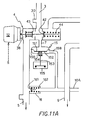
- Fig.s 11, 11A and 11B it is shortly discussed the general operation of a plant capable of supplying both heating and hot sanitary water and incorporating a valve assembly according to the invention.
- the valve assembly according to the invention is connected to a plant for supplying both heating and sanitary hot water, i.e. a plant adapted to produce hot water in a closed circuit comprising heat radiators and, upon request, to erogate tap sanitary hot water for general purposes, the plant using a same primary heat source, such as a gas burner.
- a plant for supplying both heating and sanitary hot water i.e. a plant adapted to produce hot water in a closed circuit comprising heat radiators and, upon request, to erogate tap sanitary hot water for general purposes, the plant using a same primary heat source, such as a gas burner.
- the gas burner 1 heats through a (main) finned heat exchanger 2 the water in a room heating circuit with such water being circulated by a pump P.
- the burner is fired by a microswitch 155 controlled by a manostat or pressure switch 15 to be described hereinbelow.
- This heated water reaches a valve 4 of the three-way type that under normal conditions directs the water to the radiators or radiating elements, indicated as a whole by the single element R, through the fitting 5 and is returned to the pump P through a heating return fitting 6.
- the three-way valve 4 closes the passage 5 towards the radiators and delivers the hot water to a second water/water heat exchanger 17 (for example of the metal sheet type) where such hot water heats the domestic water incoming from the fitting 8 (that is from the waterworks).
- the domestic water is then delivered through the outlet fitting (and conduit) 9 to the taps for erogating the hot water, schematically indicated by the single tap RE in the Figure.
- valve assembly according to the invention is substantially formed by two sub-assemblies or valve units I and II, enclosed by dashed squares in Fig. 11, and made almost exclusively of a composite plastic material. More particularly according to the invention, each of the sub-assemblies I and II is formed as a one-piece body of molded composite plastic material in which there are formed or mounted the various components and metal fittings.
- the first sub-assembly, or delivery distributor comprises the three-way valve 4, a fitting 3 to be connected to the main heat exchanger 2, a fitting 5 for the connection to the radiator R, an outlet fitting 9 for the domestic water and two spigots or pipe fittings 22, 23 connecting the unit with said water/water heat exchanger 17 (of known type) formed by metal sheets stacked on each other to define alternating thin passagges through which flow the hot water and the water to be heated, respectively.
- connections to the exchanger 17 are shown as conduits whereas in practice both sub-assemblies are built in such a manner that the illustrated connections are mere outlets or openings having a negligible length.
- the three-way valve 4 can be actuated either by an electric motor 12 or by a diferential pressure flow valve of the diaphragm type (not shown) connected to a depression device by two tubes.
- the motor 12 is mounted on a seat in the sub-assembly I, and secured by means 38, for example two screws or a slit ring, so as to be easily dismounted for servicing and replacing the components, if necessary.
- the electric motor 12 connected to the stem of the three-way valve 4, accomplishes a rectilinear movement upon receiving a command or enabling signal S from a manostat device 14 in the domestic water circuit, as will be described later on.
- actuating members 42 and 43 formed as flat bodies fixed to each other and axially urged by a return spring 44.
- An opening 30, provided near the fitting 3, allows the insertion of a temperature probe, usually a thermistor (not shown).
- a pressure difference manostat 15 that opens the microswitch 155 for disenabling the burner in case of lack of water in the heating plant and/or lack of pressure (pump blocking).
- Such pressure difference manostat 15 comprises a chamber 150 connected to the fitting 7, that is divided into two parts by a diaphragm 151. One of the two parts communicates through the passage of the fitting 7 with the three-way valve, whereas the other part is connected to a point upwards the pump P through a passage 158, i.e. to a zone at a lower pressure.
- a flat member or pan 152 abuts against the diaphragm 151, urged by a a spring 154 and provided with a spindle 153 protruding from the chamber 150 for acting over the microswitch 155.
- water in the plant such water is pressurized by the pump P on the side of the valve 4, with the other side being in a depression condition, and the so generated pressure difference acts over the diaphragm 151 controlling the safety microswitch 155.
- bypass valve 16 formed by a seat in which there are housed: a movable member 161 biased by a spring 162 that abuts against a spring stop 163 (see Fig. 12A).
- the bypass valve 16 When the pressure difference between the delivery and return sides reaches a predetermined high value, for example due to large load losses in the radiators, the bypass valve 16 is opened and a part of the water recirculates through the bypass connection tube 10A provided for ensuring always the passage of a certain amount of water towards the main exchanger 2.
- the unit further provides the two openings 22 and 23 fitted with sealing rings or O-rings 70, 71 for the connection to the water/water heat exchanger 17, for the inlet of the heating water and for the outlet of the domestic water, respectively.
- the connection is accomplished through a stay or tie rod 73 drawing the parts near to each other and compressing the O-rings so as to realize a sealing thereof.
- Fig. 11B illustrates with more details the second sub-assembly II, enclosed in a dashed rectangle in Fig. 11.
- This sub-assembly comprises command and control means for the three-way valve 4.
- such means comprises a pressure difference manostat 25 fitted in the sanitary tube and controlling the motor 12 on the sub-assembly I, however such means can have other different constructions, such as for example a pressure-actuated diaphragm valve.
- the second sub-assembly II further comprises a depression device 14 and the pump P. As better illustrated hereinbelow with reference to Fig.
- the construction of the sub-assembly II according to the invention comprises a one-piece or monolithic body 18 and a pump case or housing 19 adapted to contain the motor of the pump, both the body and the case being of a composite plastic materials, together with metal fittings 50, 60.
- the components of the sub-assembly II perform the following tasks.
- the tap RE for delivering hot water is opened and as long as the requested water flow rate is below a given value, such as for example 2 liters/minute, the water from the inlet fitting 8 and flowing through a short conduit 20 towards the plate heat exchanger 17, at first passes through a small hole 145 in the bored movable member 141 within the depression device 14.
- the force of the spring 146 is overcome and the water flows also through the bored movable member 141.
- manostat 25 connected to the device 14 by two conduits 142 and 144 are similar to those of the above illustrated device 15, and also this latter is completely opend at a predetermined value of the flow rate, for example 2 liters/minuute.
- conduit 142 During the water flow, the water pressure of the waterworks is applied to conduit 142, while the pressure drop is applied to conduit 144 for obtaining a signal adapted to the working of the sanitary manostat 25.
- the manostat 25 is omitted and the conduits 142, 144 are connected to said diaphragm valve.
- the construction of the sub-assembly II comprises the one-piece or monolithic body 18 and a portion of case 19, both of composite plastic material, and metal members or fittings 50, 60 to be later illustrated with more details.
- the fittings are realized as brass components and are pressing or forced into the corresponding seats or receptacles, so that in the plant installation the workman must not work on plastic materials.
- the monolithic body 18 (see Fig. 8), is moulded of a composite plastic materials, and comprises the portions IIA and IIB that are connected to each other by a connecting portion IIC.
- a housing recess 40 for the motor of the pump there is formed a housing recess 40 for the motor of the pump, an automatic venting duct 41 for the plant, a seat or receptacle 42 for a connection fitting (not shown) to the main heat exchanger 2, and a seat or receptacle 6A for the metal fitting 6 for the return of the heating water.
- portion IIB there is formed a seat for the depression device 14 and the manostat 25 with two openings 44 and 45 for the depression device and the sanitary cold water fitting, respectively.
- the connecting portion IIC there are formed two openings 32 and 33 (shown by dashed lines) for the connection to the water/water heat exchanger 17, that are substantially equivalent to the already described openings 22 and 23, and a hole 46 for the connecting tay (not shown) to the heat exchanger 17.
- the case 19 of the pump P can be shaped in different ways, in accordance with the type of pump being mounted in the assembly, and a further intermediate portion of composite plastic material (not shown in the drawings) could be provided for adjusting pumps with a shorter length.
- the openings and the seats or receptacles for receiving a threaded metal fitting are equipped with clutches or couplings (clearly shown in Fig. 9) comprising a slit in which an elastic fork is inserted that engages a groove realized in the metal component that is housed therein.
- clutches or couplings (clearly shown in Fig. 9) comprising a slit in which an elastic fork is inserted that engages a groove realized in the metal component that is housed therein.
- other known fastening means can be used, for example screws.
- Fig. 9 illustrates the brass metal body 50 provided with conduits 56, 57 and 58 communicating with each other.
- the body 50 comprises the proper threaded fitting 8 for the return of the heating water, and the portion of a clutch 51 with a groove 52 for engaging the metal fork.
- the metal body 50 further comprises a fitting 58 (shown as not threaded in Fig. 9) for water drain, a mouthpiece 53 for a safety valve (64 in Fig. 11), and an opening 54 for the connection to a filling tap RI (see Fig. 11B).
- a further opening, axially aligned with the opening 54 (and not visible in Fig. 9) is provided for the connection to an expansion tank 13 shown in Fig. 11.
- an additional outlet 55 is provided for the connection with a thermostat.
- the metal body 60 is substantially formed by a threaded fitting for the inlet of the domestic water, a portion of clutch 61 with a groove 62 for engaging the fork, and a opening 63 for the connection to a (possible) tap for water filling.
- the valve or depression device 14 comprises the following axially aligned components: a plug 81, an O-ring 82, a metal network filter 83 and a bush 84. Between the filter 83 and the bush 84 there is interposed a flow regulator 85, for example set at 12 liters/minute. A spring, housed between the seat of the movable member and the movable member 85 supplies the return force.
- the composite material forming the pieces 1, 2 and 6 is a thermoplastic polymeric material, for example of polyammide fibers, such as nylon filled with glass fibers or other materials, or a so called “technological" polymers such as the Ryton R .
- the composite plastic material used in the assembly of the invention has a very good dimensional stability and a high resistance against chemical attacks, as well as a low mold shrinkage in order to obtain the required dimensional precision of the components.
Landscapes
- Engineering & Computer Science (AREA)
- Physics & Mathematics (AREA)
- Thermal Sciences (AREA)
- Chemical & Material Sciences (AREA)
- Combustion & Propulsion (AREA)
- Mechanical Engineering (AREA)
- General Engineering & Computer Science (AREA)
- Water Supply & Treatment (AREA)
- Steam Or Hot-Water Central Heating Systems (AREA)
- Safety Valves (AREA)
- Domestic Hot-Water Supply Systems And Details Of Heating Systems (AREA)
Applications Claiming Priority (2)
| Application Number | Priority Date | Filing Date | Title |
|---|---|---|---|
| IT96MI000567A IT1284431B1 (it) | 1996-03-22 | 1996-03-22 | Gruppo idraulico con pompa integrata per impianti misti di riscaldamento e acqua sanitaria |
| ITMI960567 | 1996-03-22 |
Publications (3)
| Publication Number | Publication Date |
|---|---|
| EP0797057A2 true EP0797057A2 (de) | 1997-09-24 |
| EP0797057A3 EP0797057A3 (de) | 1998-10-14 |
| EP0797057B1 EP0797057B1 (de) | 1999-12-15 |
Family
ID=11373745
Family Applications (1)
| Application Number | Title | Priority Date | Filing Date |
|---|---|---|---|
| EP96110213A Expired - Lifetime EP0797057B1 (de) | 1996-03-22 | 1996-06-25 | Ventileinheit mit integrierter Pumpe für kombinierten Kessel zur Erzeugung von Heizwärme und Warmwasser |
Country Status (4)
| Country | Link |
|---|---|
| EP (1) | EP0797057B1 (de) |
| DE (1) | DE69605644T2 (de) |
| ES (1) | ES2142522T3 (de) |
| IT (1) | IT1284431B1 (de) |
Cited By (18)
| Publication number | Priority date | Publication date | Assignee | Title |
|---|---|---|---|---|
| EP0994311A2 (de) | 1998-10-14 | 2000-04-19 | FUGAS s.r.l. | Hydraulische Baugruppe für Heizungs-und Heisswasseranlagen , mit einem Heisswasserspeicher |
| EP1026456A1 (de) * | 1999-02-03 | 2000-08-09 | IABER S.p.A. | Hydraulische Verteilergruppe |
| EP1026457A1 (de) * | 1999-02-03 | 2000-08-09 | IABER S.p.A. | Multifunktionelles Pumpengehäuse |
| EP0911590A3 (de) * | 1997-10-20 | 2001-04-04 | Valter Falavegna | Ventileinheit mit integriertem hydraulischem Verteilsystem, insbesondere für kombinierten Wandkessel |
| FR2813950A1 (fr) * | 2000-09-14 | 2002-03-15 | Chaffoteaux Et Maury | Vanne distributrice hydraulique pour systeme de production d'eau chaude de chauffage et d'eau chaude sanitaire |
| EP0981031A3 (de) * | 1998-08-18 | 2002-07-31 | ALCO Corporation of Namdong Industrial Area 156BL/10LT | Gerät zur Heizwasserumwaltzung und Brauchwasserheizung in einem Kombikessel |
| EP1130342A3 (de) * | 2000-02-21 | 2003-04-02 | Grundfos A/S | Baueinheit für eine Kompaktheizungsanlage |
| EP1418387A1 (de) * | 2002-11-08 | 2004-05-12 | Grundfos a/s | Kompaktheizungsanlage mit zwei Heizkreisen |
| EP1650506A1 (de) * | 2004-10-19 | 2006-04-26 | GV STAMPERIE S.p.A. | Boilereinheit für Doppelfunktionsgasboiler und Boiler mit dieser Einheit |
| EP1845314A1 (de) * | 2006-04-14 | 2007-10-17 | Fugas Spa | Hydraulikbaugruppe für den Rücklauf eines Wandkessels |
| EP1847781A3 (de) * | 2006-04-19 | 2007-12-05 | Fugas Spa | Hydraulischer Kreislauf für Zentralheizungs- und Brauchwasserheizungsanlage gespeist von einer zentralen Warmwasserversorgung |
| ITPD20090018A1 (it) * | 2009-01-29 | 2010-07-30 | Italtecnica S R L | Dispositivo di raccordo particolarmente per gruppi autoclave ad elettropompa |
| EP1965139A3 (de) * | 2007-02-27 | 2013-11-13 | Fugas Spa | Hydraulikaggregat mit zwei sekundären Wärmetauschern für Gasboilersysteme |
| EP3012552A1 (de) * | 2014-10-21 | 2016-04-27 | Grundfos Holding A/S | Baueinheit für eine Kompaktheizungsanlage |
| CN107076461A (zh) * | 2014-11-19 | 2017-08-18 | 庆东纳碧安株式会社 | 具有与水管管道一体化的止回阀的锅炉 |
| ITUA20164036A1 (it) * | 2016-06-01 | 2017-12-01 | O T M A S N C Di Spaggiari & C | Gruppo idraulico per un impianto di produzione di acqua calda |
| WO2022250636A1 (en) * | 2021-05-24 | 2022-12-01 | Serdar Plastik Sanayi Ve Ticaret A.Ş. | Hydroblock |
| EP4348128A4 (de) * | 2021-05-24 | 2025-03-26 | Serdar Plastik Sanayi Ve Ticaret A.S. | Hydroblock |
Families Citing this family (2)
| Publication number | Priority date | Publication date | Assignee | Title |
|---|---|---|---|---|
| DE102004049512B4 (de) * | 2004-10-11 | 2013-11-28 | Bürkert Werke GmbH | Modulares Gehäusesystem für fluidische Steuer- und Regelgeräte |
| CN102042637B (zh) * | 2010-09-07 | 2013-04-03 | 浙江恒翔实业发展有限公司 | 采暖系统用生活水和采暖水切换装置 |
Family Cites Families (3)
| Publication number | Priority date | Publication date | Assignee | Title |
|---|---|---|---|---|
| IT206735Z2 (it) * | 1986-05-09 | 1987-10-01 | Beretta A S P A | Circuito idraulico integrato per la produzione di acqua calda per riscaldamento e uso sanitario. |
| IT230482Y1 (it) * | 1993-11-10 | 1999-06-07 | Beretta A Ing Spa | Gruppo idraulico estremamente compatto per caldaie murali a gas |
| IT1273666B (it) * | 1994-07-20 | 1997-07-09 | Giuseppe Fugazza | Gruppo idraulico perfezionato per impianti misti di riscaldamento e acqua sanitaria |
-
1996
- 1996-03-22 IT IT96MI000567A patent/IT1284431B1/it active IP Right Grant
- 1996-06-25 DE DE69605644T patent/DE69605644T2/de not_active Expired - Lifetime
- 1996-06-25 EP EP96110213A patent/EP0797057B1/de not_active Expired - Lifetime
- 1996-06-25 ES ES96110213T patent/ES2142522T3/es not_active Expired - Lifetime
Cited By (24)
| Publication number | Priority date | Publication date | Assignee | Title |
|---|---|---|---|---|
| EP0911590A3 (de) * | 1997-10-20 | 2001-04-04 | Valter Falavegna | Ventileinheit mit integriertem hydraulischem Verteilsystem, insbesondere für kombinierten Wandkessel |
| EP1656978A1 (de) * | 1997-10-20 | 2006-05-17 | Valter Falavegna | Pumpenentlüftungsvorrichtung, insbesondere für Wandheizkessel |
| EP0981031A3 (de) * | 1998-08-18 | 2002-07-31 | ALCO Corporation of Namdong Industrial Area 156BL/10LT | Gerät zur Heizwasserumwaltzung und Brauchwasserheizung in einem Kombikessel |
| EP0994311A2 (de) | 1998-10-14 | 2000-04-19 | FUGAS s.r.l. | Hydraulische Baugruppe für Heizungs-und Heisswasseranlagen , mit einem Heisswasserspeicher |
| EP0994311A3 (de) * | 1998-10-14 | 2002-09-18 | Fugas Spa | Hydraulische Baugruppe für Heizungs-und Heisswasseranlagen , mit einem Heisswasserspeicher |
| EP1026456A1 (de) * | 1999-02-03 | 2000-08-09 | IABER S.p.A. | Hydraulische Verteilergruppe |
| EP1384960A1 (de) * | 1999-02-03 | 2004-01-28 | IABER S.p.A. | Kessel |
| EP1026457A1 (de) * | 1999-02-03 | 2000-08-09 | IABER S.p.A. | Multifunktionelles Pumpengehäuse |
| EP1130342A3 (de) * | 2000-02-21 | 2003-04-02 | Grundfos A/S | Baueinheit für eine Kompaktheizungsanlage |
| FR2813950A1 (fr) * | 2000-09-14 | 2002-03-15 | Chaffoteaux Et Maury | Vanne distributrice hydraulique pour systeme de production d'eau chaude de chauffage et d'eau chaude sanitaire |
| EP1188991A1 (de) * | 2000-09-14 | 2002-03-20 | Chaffoteaux Et Maury | Hydraulisches Verteilerventil für kombinierte Heizungsanlage |
| EP1418387A1 (de) * | 2002-11-08 | 2004-05-12 | Grundfos a/s | Kompaktheizungsanlage mit zwei Heizkreisen |
| EP1650506A1 (de) * | 2004-10-19 | 2006-04-26 | GV STAMPERIE S.p.A. | Boilereinheit für Doppelfunktionsgasboiler und Boiler mit dieser Einheit |
| EP1845314A1 (de) * | 2006-04-14 | 2007-10-17 | Fugas Spa | Hydraulikbaugruppe für den Rücklauf eines Wandkessels |
| EP1847781A3 (de) * | 2006-04-19 | 2007-12-05 | Fugas Spa | Hydraulischer Kreislauf für Zentralheizungs- und Brauchwasserheizungsanlage gespeist von einer zentralen Warmwasserversorgung |
| EP1965139A3 (de) * | 2007-02-27 | 2013-11-13 | Fugas Spa | Hydraulikaggregat mit zwei sekundären Wärmetauschern für Gasboilersysteme |
| ITPD20090018A1 (it) * | 2009-01-29 | 2010-07-30 | Italtecnica S R L | Dispositivo di raccordo particolarmente per gruppi autoclave ad elettropompa |
| EP3012552A1 (de) * | 2014-10-21 | 2016-04-27 | Grundfos Holding A/S | Baueinheit für eine Kompaktheizungsanlage |
| CN107076461A (zh) * | 2014-11-19 | 2017-08-18 | 庆东纳碧安株式会社 | 具有与水管管道一体化的止回阀的锅炉 |
| CN107076461B (zh) * | 2014-11-19 | 2020-01-31 | 庆东纳碧安株式会社 | 具有与水管管道一体化的止回阀的锅炉 |
| ITUA20164036A1 (it) * | 2016-06-01 | 2017-12-01 | O T M A S N C Di Spaggiari & C | Gruppo idraulico per un impianto di produzione di acqua calda |
| EP3252394A1 (de) * | 2016-06-01 | 2017-12-06 | O.T.M.A. S.N.C. di Spaggiari & C. | Hydraulikbaugruppe für ein warmwassererzeugungssystem |
| WO2022250636A1 (en) * | 2021-05-24 | 2022-12-01 | Serdar Plastik Sanayi Ve Ticaret A.Ş. | Hydroblock |
| EP4348128A4 (de) * | 2021-05-24 | 2025-03-26 | Serdar Plastik Sanayi Ve Ticaret A.S. | Hydroblock |
Also Published As
| Publication number | Publication date |
|---|---|
| IT1284431B1 (it) | 1998-05-21 |
| EP0797057B1 (de) | 1999-12-15 |
| DE69605644T2 (de) | 2000-05-31 |
| ITMI960567A0 (de) | 1996-03-22 |
| ITMI960567A1 (it) | 1997-09-22 |
| EP0797057A3 (de) | 1998-10-14 |
| ES2142522T3 (es) | 2000-04-16 |
| DE69605644D1 (de) | 2000-01-20 |
Similar Documents
| Publication | Publication Date | Title |
|---|---|---|
| EP0797057B1 (de) | Ventileinheit mit integrierter Pumpe für kombinierten Kessel zur Erzeugung von Heizwärme und Warmwasser | |
| US7621295B2 (en) | System for controlling fluid flow to an appliance | |
| CA2539958C (en) | Isolation valve with valve in drain | |
| US4756475A (en) | Gas-fired boiler | |
| US5323803A (en) | Instant hot water device | |
| DK1832816T3 (en) | Hydraulic device, hydraulic device, hydraulic system and method for using it | |
| EP0568122B1 (de) | Ventilanordnung für Anlagen, die sowohl für Heizungs- als auch für Haushaltsheisswasser vorgesehen ist | |
| US11555617B2 (en) | Hydraulic unit for a heating or air-conditioning system | |
| EP0693658A1 (de) | Verbesserte Ventilanordnung für Anlagen, die sowohl für Heizungs- als auch für Haushaltsheisswasser vorgesehen ist | |
| EP1847781A2 (de) | Hydraulischer Kreislauf für Zentralheizungs- und Brauchwasserheizungsanlage gespeist von einer zentralen Warmwasserversorgung | |
| EP0633993B1 (de) | Fluid-steueranlage und verfahren zum betrieb derselben | |
| EP1831609B1 (de) | Wärmetauscher für einen kombikessel und kombikessel mit diesem wärmetauscher | |
| CZ256097A3 (cs) | Hydraulická konstrukční skupina pro kombinované zařízení na topnou a užitkovou vodu | |
| EP0466010B1 (de) | Ventilvorrichtung für Heizungsanlagen | |
| US6354813B1 (en) | Hydraulically activated three-way-valve | |
| EP1065447A2 (de) | Verteiler für thermisches System mit Zwangsumlauf | |
| EP1845314A1 (de) | Hydraulikbaugruppe für den Rücklauf eines Wandkessels | |
| EP0447851A2 (de) | Dreiwegeventil | |
| US4397418A (en) | Control unit for central heating systems | |
| CN100441961C (zh) | 用于供热系统的调节装置 | |
| NL2015440B1 (en) | Satellite for central heating or for teleheating with multifunction presettings. | |
| EP4446661A1 (de) | Verteilervorrichtung für wasser und heizungsanlage für ein gebäude | |
| EP0994311A2 (de) | Hydraulische Baugruppe für Heizungs-und Heisswasseranlagen , mit einem Heisswasserspeicher | |
| EP0957419A1 (de) | Verbesserungen für eine Wasserheizanlage | |
| CN113513614A (zh) | 一种恒温压差组合阀组成的混水单元 |
Legal Events
| Date | Code | Title | Description |
|---|---|---|---|
| PUAI | Public reference made under article 153(3) epc to a published international application that has entered the european phase |
Free format text: ORIGINAL CODE: 0009012 |
|
| AK | Designated contracting states |
Kind code of ref document: A2 Designated state(s): DE ES FR GB |
|
| RBV | Designated contracting states (corrected) |
Designated state(s): DE ES FR GB |
|
| PUAL | Search report despatched |
Free format text: ORIGINAL CODE: 0009013 |
|
| AK | Designated contracting states |
Kind code of ref document: A3 Designated state(s): DE ES FR GB |
|
| RHK1 | Main classification (correction) |
Ipc: F24D 3/08 |
|
| 17P | Request for examination filed |
Effective date: 19981105 |
|
| GRAG | Despatch of communication of intention to grant |
Free format text: ORIGINAL CODE: EPIDOS AGRA |
|
| 17Q | First examination report despatched |
Effective date: 19990414 |
|
| GRAG | Despatch of communication of intention to grant |
Free format text: ORIGINAL CODE: EPIDOS AGRA |
|
| GRAH | Despatch of communication of intention to grant a patent |
Free format text: ORIGINAL CODE: EPIDOS IGRA |
|
| GRAH | Despatch of communication of intention to grant a patent |
Free format text: ORIGINAL CODE: EPIDOS IGRA |
|
| GRAA | (expected) grant |
Free format text: ORIGINAL CODE: 0009210 |
|
| AK | Designated contracting states |
Kind code of ref document: B1 Designated state(s): DE ES FR GB |
|
| ET | Fr: translation filed | ||
| REF | Corresponds to: |
Ref document number: 69605644 Country of ref document: DE Date of ref document: 20000120 |
|
| REG | Reference to a national code |
Ref country code: ES Ref legal event code: FG2A Ref document number: 2142522 Country of ref document: ES Kind code of ref document: T3 |
|
| PLBE | No opposition filed within time limit |
Free format text: ORIGINAL CODE: 0009261 |
|
| STAA | Information on the status of an ep patent application or granted ep patent |
Free format text: STATUS: NO OPPOSITION FILED WITHIN TIME LIMIT |
|
| 26N | No opposition filed | ||
| REG | Reference to a national code |
Ref country code: GB Ref legal event code: IF02 |
|
| REG | Reference to a national code |
Ref country code: FR Ref legal event code: CD Ref country code: FR Ref legal event code: CA |
|
| REG | Reference to a national code |
Ref country code: FR Ref legal event code: PLFP Year of fee payment: 20 |
|
| PGFP | Annual fee paid to national office [announced via postgrant information from national office to epo] |
Ref country code: GB Payment date: 20150630 Year of fee payment: 20 Ref country code: DE Payment date: 20150626 Year of fee payment: 20 Ref country code: ES Payment date: 20150610 Year of fee payment: 20 |
|
| PGFP | Annual fee paid to national office [announced via postgrant information from national office to epo] |
Ref country code: FR Payment date: 20150605 Year of fee payment: 20 |
|
| REG | Reference to a national code |
Ref country code: DE Ref legal event code: R071 Ref document number: 69605644 Country of ref document: DE |
|
| REG | Reference to a national code |
Ref country code: GB Ref legal event code: PE20 Expiry date: 20160624 |
|
| PG25 | Lapsed in a contracting state [announced via postgrant information from national office to epo] |
Ref country code: GB Free format text: LAPSE BECAUSE OF EXPIRATION OF PROTECTION Effective date: 20160624 |
|
| REG | Reference to a national code |
Ref country code: ES Ref legal event code: FD2A Effective date: 20160930 |
|
| PG25 | Lapsed in a contracting state [announced via postgrant information from national office to epo] |
Ref country code: ES Free format text: LAPSE BECAUSE OF EXPIRATION OF PROTECTION Effective date: 20160626 |