EP0980822B1 - Flugzeugstirnstruktur - Google Patents
Flugzeugstirnstruktur Download PDFInfo
- Publication number
- EP0980822B1 EP0980822B1 EP99402079A EP99402079A EP0980822B1 EP 0980822 B1 EP0980822 B1 EP 0980822B1 EP 99402079 A EP99402079 A EP 99402079A EP 99402079 A EP99402079 A EP 99402079A EP 0980822 B1 EP0980822 B1 EP 0980822B1
- Authority
- EP
- European Patent Office
- Prior art keywords
- fore
- landing gear
- aircraft
- compartment
- partition
- Prior art date
- Legal status (The legal status is an assumption and is not a legal conclusion. Google has not performed a legal analysis and makes no representation as to the accuracy of the status listed.)
- Expired - Lifetime
Links
Images

Classifications
-
- B—PERFORMING OPERATIONS; TRANSPORTING
- B64—AIRCRAFT; AVIATION; COSMONAUTICS
- B64C—AEROPLANES; HELICOPTERS
- B64C25/00—Alighting gear
- B64C25/02—Undercarriages
- B64C25/08—Undercarriages non-fixed, e.g. jettisonable
- B64C25/10—Undercarriages non-fixed, e.g. jettisonable retractable, foldable, or the like
- B64C25/14—Undercarriages non-fixed, e.g. jettisonable retractable, foldable, or the like fore-and-aft
-
- B—PERFORMING OPERATIONS; TRANSPORTING
- B64—AIRCRAFT; AVIATION; COSMONAUTICS
- B64C—AEROPLANES; HELICOPTERS
- B64C1/00—Fuselages; Constructional features common to fuselages, wings, stabilising surfaces or the like
- B64C1/06—Frames; Stringers; Longerons ; Fuselage sections
- B64C1/068—Fuselage sections
- B64C1/0683—Nose cones
-
- B—PERFORMING OPERATIONS; TRANSPORTING
- B64—AIRCRAFT; AVIATION; COSMONAUTICS
- B64C—AEROPLANES; HELICOPTERS
- B64C1/00—Fuselages; Constructional features common to fuselages, wings, stabilising surfaces or the like
- B64C1/06—Frames; Stringers; Longerons ; Fuselage sections
- B64C1/10—Bulkheads
-
- B—PERFORMING OPERATIONS; TRANSPORTING
- B64—AIRCRAFT; AVIATION; COSMONAUTICS
- B64C—AEROPLANES; HELICOPTERS
- B64C1/00—Fuselages; Constructional features common to fuselages, wings, stabilising surfaces or the like
- B64C1/36—Fuselages; Constructional features common to fuselages, wings, stabilising surfaces or the like adapted to receive antennas or radomes
Definitions
- the invention relates to a front structure aircraft, particularly suitable for aircraft large and very large commercial vehicles.
- the front structure of a wide-body aircraft includes a compartment pressurized 1, extended at the front by a radome 2 in which is defined by a radar chamber 3.
- a flat floor 4 supports in particular the cockpit and fittings commercial.
- a door or access doors 5 can be provided under the fuselage in the pressurized area, behind the radar chamber 3, to allow the ground personnel to enter the part of the pressurized compartment 1 located below the floor 4, in order to carry out maintenance operations there usual.
- a train compartment 6 not pressurized is provided inside the fuselage, to receive the front landing gear 7, in its retracted position.
- Train compartment 6 is separated from pressurized compartment 1 by a number of partitions. These partitions include two substantially vertical side partitions, one partition front, a rear wall as well as a ceiling often tilted, downward from front to the rear, when the wheels are in front of the undercarriage leg anchor fittings retracted position.
- the usual design of the train 6 limits the volume available, in particular for front landing gear wheels and tires 7, and in particular may prohibit the fitting of wheels bigger during the evolution of the plane.
- the constraints that the train must bear front landing leads to give to the wheels and to the tires of this train of dimensions which are not more compatible with a train compartment thus designed.
- the subject of the invention is precisely a aircraft front structure, the design of which is totally original allows him to solve all the problems posed by the structures before conception Traditional.
- the front plane structure conforms to the invention eliminates the access door overlooking the outside and decreasing very appreciably the frequency of dismantling the radome limited to the need for intervention on the radome itself or on the surrounding structure. This is results in a marked improvement in aerodynamic characteristics of the aircraft.
- the front structure according to the invention also allows the volume to be easily adjusted available in the train box in the dimensions of front landing gear wheels and tires imposed by an increase in the mass of the aircraft at lift-off.
- a front structure airplane comprising a pressurized compartment and a unpressurized train compartment, suitable for housing a train front landing, in a retracted state thereof, characterized in that the unpressurized train compartment forms an extreme lower part before said front structure.
- the train compartment is extends under the cockpit to the point before the plane. It is therefore no longer separated from the compartment pressurized only by a ceiling and a rear partition.
- the train compartment has an extension backwards, beyond the rear wall.
- the train front landing is then articulated in said extension backwards, so as to extend towards the front in the train compartment, when he is in his returned state.
- the rearward extension of the train compartment is delimited by side partitions which can be either substantially vertical or, preferably, tilted so as to approach upwards.
- This access door can in particular have a shape substantially oval, with a large vertical axis, for a better overall structural strength.
- the wheel or wheels of the front landing gear are then located near this front partition, when the train is in its returned state.
- a guardrail and / or a bursting net is advantageously placed inside thereof.
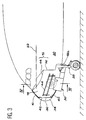
- Figures 3 to 5 illustrate a mode of preferred construction of a front plane structure according to the invention. Such a structure before advantageously applies to a wide-body aircraft or very large carrier.
- the reference 10 designates the wall forming the outer shell of the structure before the plane.
- the internal volume of the aircraft, defined externally by the wall 10, is divided internally in two zones by a partition of watertight separation 12.
- the partition watertight 12 includes a ceiling 14 and a partition rear 16, the edges of which are connected to each other as well as wall 10.
- the area under the ceiling 14 and in front of the rear wall 16 forms the part lower extreme front of the structure before the plane. According to the invention, this area constitutes the train compartment 18 and it is not pressurized.
- the area above the ceiling 14 and behind the rear partition 16 constitutes the pressurized compartment 20 of the aircraft.
- This zone contains a flat floor 22, located above the ceiling 14.
- the floor 22 supports in particular the cockpit and the commercial arrangements of the aircraft.
- the pressurized compartment 20 can be arranged so any, without departing from the scope of the invention. Through Therefore, no description will be made of it.
- the ceiling 14 is curved downwards. This feature allows the ceiling 14 to support the pressure difference that exists between the unpressurized train 18 and the pressurized compartment 20, without it being necessary to give it too large dimensions.
- stiffeners (Figure 5) advantageously equip the partition of separation 12, for example on the side of the train compartment 18.
- these stiffeners 24 have the form of squares whose branch substantially vertical lower rests on the rear bulkhead 16 and of which the upper branch substantially horizontal rests on the ceiling 14.
- Train compartment 18 has an extension to the rear 18a, which extends said box beyond the rear partition 16, in the lower part of the front structure.
- This extension 18a which facilitates in particularly the attachment of the train leg and the resumption of efforts, is delimited in particular by two side partitions 26 ( Figure 5).
- the side walls 26 are inclined so as to get closer up. This arrangement increases the space available in the compartment pressurized 20, on either side of extension 18a, between it and the wall 10.
- the side partitions 26 can be substantially vertical. Indeed, the large size of the plane and the reduced width of extension 18a make the spaces formed accessible anyway between this extension and the wall 10.
- Train compartment 18, extended rearwards by its extension 18a, allows to lodge in the front structure of the aircraft a landing gear front 28 (Figures 2 and 3) large.
- the original arrangement of the train compartment allows so the use of a front landing gear 28 whose wheels and tires have sizes adapted to the importance of the constraints applied on the train in the case of a very large aircraft, of which the maximum take-off mass can in particular be more than 500 tonnes.
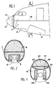
- Figures 2 and 4 which both represent a section of the plane in line with the wheels, in the folded state of the train front landing, clearly illustrates the gain dimension authorized by the invention (Figure 4), by compared to the prior art ( Figure 2).
- the landing gear before 28 is articulated in the extension 18a of the box of train 18. It is brought into its retracted position in swiveling forward so that its wheels and its tires are fully housed inside from train compartment 18.
- a set of hatches 30 then closes an opening 32 practiced at the bottom of the wall 10, opposite the train compartment 18 and its rearward extension 18a.
- the dimensions of the opening 32 are adapted to allow the landing gear to exit 28, after opening the doors 30, on landing.
- At least one access door 34 is provided in the rear partition 16.
- This access door 34 allows to access the pressurized compartment 20, below the floor 22, passing through the train compartment 18. From preferably, the access door 34 has a shape substantially oval, whose major axis is inclined substantially vertically. This shape allows do not penalize the structural strength of the partition rear 16. Door 34 is placed between two stiffeners 24 adjacent.
- a radar chamber 36 forms the nose of the front structure of the aircraft.
- This room radar is bounded towards the front by a radome 38 which continuously extends the wall 10 of the aircraft.
- the radome 38 is attached to the outer wall 10, of usual way, by fixing means removable (not shown) such as screws and / or hinges.
- the radar chamber 36 is immediately adjacent to the box of train 18, from which it is separated by a partition before 40.
- At least one access opening 42 provided in the front partition 40, gives access to the room radar 36, in particular for carrying out operations there maintenance, from train compartment 18.
- This access maintenance can be done in the rain (whatever whatever the weather) the plane outside then that today the maintenance of the radar antenna requires to shelter the plane.
- This arrangement allows perform the usual maintenance operations without have to remove the radome 38.
- the outcrop aerodynamics of the latter on the wall 10 of the aircraft can thus be preserved in better conditions that on planes using solutions traditional.
- a guardrail 44 ( Figure 3) travels in the latter. More specifically, the guardrail 44 includes two side parts which extend towards the front from the rear bulkhead 16, as well as a front part which runs transversely along the front partition 40.
- the railing 44 allows in particular the ground personnel to safely intervene in the radar chamber 36 and safely access the pressurized compartment 20, behind the partition 16, through access door 34.
- Guardrail 44 can also be used for stretch a net (not shown) near the ceiling 14.
- a such a net avoids any injury to the crew or damage to the cockpit following the projection pieces of the front landing gear 28 toward the ceiling 14, if the tires burst or break another part of the landing or landing gear taxiing on the ground.
- train compartment 18 Access to train compartment 18 is possible by an external movable staircase or a forklift.
- a on-board folding ladder (not shown) can also be placed for this purpose in the train compartment 18.
- the invention is not limited to preferred embodiment which has just been described.
- the shape of the ceiling 14 and that of the box train 18 can be different, without going outside the framework of the invention.
Landscapes
- Engineering & Computer Science (AREA)
- Mechanical Engineering (AREA)
- Aviation & Aerospace Engineering (AREA)
- Aiming, Guidance, Guns With A Light Source, Armor, Camouflage, And Targets (AREA)
- Tires In General (AREA)
Claims (13)
- Flugzeugvorderstruktur, umfassend ein unter Druck gesetztes Abteil (20) und einen nicht unter Druck gesetzten Fahrgestellkasten (18), der dazu ausgelegt ist, ein vorderes Fahrgestell (28) in seinem eingefahrenen Zustand aufzunehmen, dadurch gekennzeichnet, dass der nicht unter Druck gesetzte Fahrgestellkasten (18) einen untersten Vorderbereich der Stirnstruktur bildet.
- Flugzeugvorderstruktur nach Anspruch 1, bei der der Fahrgestellkasten (18) von dem unter Druck gesetzten Abteil (20) durch eine Decke (14) sowie eine Rückwand (16) getrennt ist.
- Flugzeugvorderstruktur nach Anspruch 2, bei der der Fahrgestellkasten (18) eine Verlängerung nach hinten (18a) über die Rückwand (16) hinaus umfasst, wobei das vordere Fahrgestell (28) in der Verlängerung nach hinten (18a) derart angelenkt ist, dass es sich in seinem eingefahrenen Zustand nach vorne in den Fahrgestellkasten (18) erstreckt.
- Flugzeugvorderstruktur nach Anspruch 3, bei der die Verlängerung nach hinten (18a) Seitenwände (26) aufweist, die derart geneigt sind, dass sie sich nach oben hin einander annähern.
- Flugzeugvorderstruktur nach Anspruch 3, bei der die Verlängerung nach hinten (18a) im Wesentlichen vertikale Seitenwände (26) aufweist.
- Flugzeugvorderstruktur nach einem der Ansprüche 2 bis 5, bei der die Decke (14) nach unten gewölbt ist.
- Flugzeugvorderstruktur nach einem der Ansprüche 2 bis 6, bei der wenigstens eine Zugangstür (34) in der Rückwand (16) vorgesehen ist.
- Flugzeugvorderstruktur nach Anspruch 7, bei der die Zugangstür (34) eine im Wesentlichen ovale Form mit im Wesentlichen vertikaler Hauptachse aufweist.
- Flugzeugvorderstruktur nach einem der Ansprüche 2 bis 8, bei der die Decke (14) und die Rückwand (16) mit Aussteifungselementen (24) ausgestattet sind.
- Flugzeugvorderstruktur nach einem der vorhergehenden Ansprüche, bei der eine außen durch ein Radom (38) begrenzte Radarkammer (36) vor dem Fahrgestellkasten (18) vorgesehen und von diesem durch eine Vorderwand (40) getrennt ist, die mit wenigstens einer Zugangsöffnung (42) versehen ist.
- Flugzeugvorderstruktur nach Anspruch 10, bei der das vordere Fahrgestell (28) mit wenigstens einem Rad ausgestattet ist, das dazu ausgelegt ist, im eingefahrenen Zustand des Fahrgestells in der Nähe der Vorderwand (40) angeordnet zu sein.
- Flugzeugvorderstruktur nach einem der Ansprüche 2 bis 6, bei der im Fahrgestellkasten (18) ein Geländer (44) angeordnet ist.
- Flugzeugvorderstruktur nach Anspruch 12, bei der das Geländer (44) ein Netz zum Schutz der Decke (14) des Fahrgestellkastens (18) trägt.
Applications Claiming Priority (2)
| Application Number | Priority Date | Filing Date | Title |
|---|---|---|---|
| FR9810550A FR2782495B1 (fr) | 1998-08-19 | 1998-08-19 | Structure avant d'avion |
| FR9810550 | 1998-08-19 |
Publications (2)
| Publication Number | Publication Date |
|---|---|
| EP0980822A1 EP0980822A1 (de) | 2000-02-23 |
| EP0980822B1 true EP0980822B1 (de) | 2003-07-30 |
Family
ID=9529778
Family Applications (1)
| Application Number | Title | Priority Date | Filing Date |
|---|---|---|---|
| EP99402079A Expired - Lifetime EP0980822B1 (de) | 1998-08-19 | 1999-08-17 | Flugzeugstirnstruktur |
Country Status (7)
| Country | Link |
|---|---|
| US (1) | US6213428B1 (de) |
| EP (1) | EP0980822B1 (de) |
| CN (1) | CN1098194C (de) |
| DE (1) | DE69909914T2 (de) |
| ES (1) | ES2205735T3 (de) |
| FR (1) | FR2782495B1 (de) |
| RU (1) | RU2228881C2 (de) |
Families Citing this family (48)
| Publication number | Priority date | Publication date | Assignee | Title |
|---|---|---|---|---|
| US6213426B1 (en) * | 1999-07-09 | 2001-04-10 | The Boeing Company | Monolithic structure with redundant load paths |
| DE10145276B4 (de) * | 2001-09-14 | 2008-04-10 | Deutsches Zentrum für Luft- und Raumfahrt e.V. | Flugzeug, insbesondere Passagierflugzeug, mit einem Rumpf, der eine tragende Primärstruktur und einen Frachtraum umfasst |
| GB0208963D0 (en) * | 2002-04-19 | 2002-05-29 | Bae Systems Plc | Landing gear door assembly |
| AU2003294227A1 (en) * | 2002-10-10 | 2004-05-04 | The Boing Company | Integrated aircraft windshields and their manufacture methods |
| DE10343627B4 (de) * | 2003-09-20 | 2014-03-06 | Eads Deutschland Gmbh | Verschlusselement für einen Bereich der Außenhaut eines Luftfahrzeugs |
| FR2864020B1 (fr) * | 2003-12-19 | 2006-02-10 | Airbus France | Nez d'avion avec bouclier |
| FR2893587B1 (fr) * | 2005-11-21 | 2009-06-05 | Airbus France Sas | Case de train a structure dissociee |
| FR2893588B1 (fr) * | 2005-11-21 | 2008-02-01 | Airbus France Sas | Case de train a structure en caissons |
| FR2901240B1 (fr) * | 2006-05-17 | 2009-01-09 | Airbus France Sas | Poutre interne composite pour renforcer la structure d'un aeronef |
| DE102006025388B4 (de) * | 2006-05-31 | 2009-10-29 | Airbus Deutschland Gmbh | Leitungssystemanordnung in einem einen Rumpf aufweisenden Luft- oder Raumfahrzeug |
| FR2903656B1 (fr) * | 2006-07-12 | 2008-09-26 | Airbus France Sas | Case de rangement du train avant d'un avion. |
| FR2903661B1 (fr) * | 2006-07-12 | 2008-11-28 | Airbus France Sas | Avion de transport de passagers |
| US8016234B2 (en) * | 2006-09-12 | 2011-09-13 | Airbus Deutschland Gmbh | Airframe structure of an aircraft or spacecraft |
| FR2905929B1 (fr) * | 2006-09-14 | 2009-04-10 | Airbus France Sas | Aeronef comportant une case de train d'atterrissage permettant une meilleure integration du train d'atterrissage |
| FR2906524B1 (fr) * | 2006-09-28 | 2008-10-31 | Airbus France Sas | Cloison de separation d'une chambre radar d'aeronef et d'une case de train avant |
| FR2910875B1 (fr) * | 2007-01-03 | 2009-10-09 | Airbus France Sas | Partie avant d'aeronef comprenant une cloison plane entre une zone pressurisee et une zone de logement de train non pressurisee. |
| FR2917369B1 (fr) * | 2007-06-15 | 2009-08-07 | Airbus France Sas | Case de train d'atterrissage a encombrement reduit |
| US7798444B2 (en) * | 2007-09-24 | 2010-09-21 | The Boeing Company | Landing gear system and load distribution |
| US7641146B2 (en) * | 2007-09-24 | 2010-01-05 | The Boeing Company | Aircraft nose landing gear enclosure |
| FR2925462B1 (fr) * | 2007-12-20 | 2010-07-30 | Airbus France | Case de rangement d'un train avant pour aeronef |
| FR2933377B1 (fr) * | 2008-07-01 | 2011-04-15 | Airbus France | Avion a train d'atterrissage avant recule |
| FR2950199B1 (fr) * | 2009-09-11 | 2011-08-26 | Airbus Operations Sas | Radome et dispositif de fixation de ce radome a un aeronef |
| CN101850844B (zh) * | 2010-05-24 | 2013-04-10 | 南京航空航天大学 | 一种飞机起落架 |
| FR2962410B1 (fr) | 2010-07-09 | 2013-07-12 | Airbus Operations Sas | Procede de reglage des trappes de case de train d'atterrissage et trappe de mise en oeuvre |
| FR2969119B1 (fr) * | 2010-12-17 | 2013-02-08 | Airbus Operations Sas | Partie avant d'un fuselage d'aeronef integrant une case de rangement de train d'atterrissage |
| FR2983170B1 (fr) * | 2011-11-30 | 2014-09-19 | Airbus Operations Sas | Structure avant de fuselage d'aeronef comprenant un train d'atterrissage |
| FR2983826B1 (fr) * | 2011-12-12 | 2013-12-20 | Airbus Operations Sas | Structure avant d'avion perfectionnee a compartiment pour train d'atterrissage. |
| FR2983825B1 (fr) * | 2011-12-12 | 2014-01-10 | Airbus Operations Sas | Structure avant d'avion et de case de rangement de train d'atterrissage avant |
| FR2999524B1 (fr) * | 2012-12-17 | 2015-02-20 | Airbus Operations Sas | Fond etanche avant d'aeronef comprenant des renfoncements pour le logement d'equipements de cockpit |
| US9199713B2 (en) * | 2013-07-08 | 2015-12-01 | The Boeing Company | Pressure panels |
| FR3030442B1 (fr) * | 2014-12-18 | 2017-01-27 | Airbus Operations Sas | Pointe avant d'aeronef equipee d'un cadre de jonction entre la case de train d'atterrissage et la peau exterieure du fuselage |
| FR3032420B1 (fr) * | 2015-02-11 | 2017-01-13 | Airbus Operations Sas | Cabine de pilotage d'un avion equipee d'une evacuation de secours |
| EP3059156B1 (de) * | 2015-02-23 | 2020-04-01 | Airbus Operations, S.L. | Flaches geknicktes Heckdruckschott |
| FR3039131B1 (fr) * | 2015-07-24 | 2019-06-07 | Airbus Operations | Trappe arriere de case de train d'atterrissage comprenant un orifice de passage d'air et un organe d'obturation de celui-ci |
| FR3045008B1 (fr) * | 2015-12-11 | 2018-01-12 | Airbus Operations | Procede et systeme pour la commande de trappes avant et arriere couplees d’une case de train d’atterrissage d’aeronef. |
| US10059426B2 (en) * | 2016-04-29 | 2018-08-28 | Embraer S.A. | Quick connection assemblies especially useful for coupling aircraft antenna fairings to airframe structures |
| US10926857B2 (en) * | 2016-06-17 | 2021-02-23 | The Boeing Company | Pressurized bulkhead |
| FR3071478B1 (fr) * | 2017-09-26 | 2021-12-03 | Airbus Operations Sas | Procede de fabrication modulaire de la partie avant d'un fuselage d'aeronef et flotte d'aeronefs obtenue |
| RU2678729C1 (ru) * | 2018-03-13 | 2019-01-31 | Общество с ограниченной ответственностью "Конструкторское бюро "Современные авиационные технологии" | Носовая часть фюзеляжа летательного аппарата |
| FR3086270A1 (fr) * | 2018-09-20 | 2020-03-27 | Airbus Operations | Module de train d'atterrissage avant pour aeronef |
| US11465729B2 (en) | 2018-09-24 | 2022-10-11 | Airbus Operations Sas | Method for modular construction of the front part of an aircraft fuselage and fleet of aircraft obtained |
| CN109720538B (zh) * | 2018-11-12 | 2023-08-01 | 中航通飞华南飞机工业有限公司 | 一种飞机机身侧面内置轮舱结构 |
| AU2020205348A1 (en) * | 2019-08-02 | 2021-02-18 | The Boeing Company | Nose structure for an aircraft and method of making an aircraft |
| US11279470B2 (en) | 2019-08-02 | 2022-03-22 | The Boeing Company | Aircraft and nose structure for an aircraft |
| US11420731B2 (en) | 2019-08-02 | 2022-08-23 | The Boeing Company | Nose structure for an aircraft |
| US11014691B2 (en) | 2019-08-02 | 2021-05-25 | The Boeing Company | Nose structure for an aircraft and method of making an aircraft |
| US11655016B2 (en) * | 2020-04-06 | 2023-05-23 | The Boeing Company | Pressurized monocoque structure with abrupt change in shape |
| CN114275150B (zh) * | 2022-01-19 | 2024-05-14 | 中国商用飞机有限责任公司 | 用于辅助起落架应急放的舱门装置及包括该装置的飞机 |
Family Cites Families (8)
| Publication number | Priority date | Publication date | Assignee | Title |
|---|---|---|---|---|
| US2685420A (en) * | 1951-11-16 | 1954-08-03 | Vincent J Burnelli | Airplane with lifting fuselage, landing flaps, and quadricycle landing gear |
| US3335981A (en) * | 1966-05-31 | 1967-08-15 | Lockheed Aircraft Corp | Retractable front landing gear for cargo aircraft |
| US3653615A (en) * | 1969-06-03 | 1972-04-04 | Spence William | Aircraft nose opening mechanism |
| US3877665A (en) * | 1969-09-09 | 1975-04-15 | Ver Flugtechnische Werke | Fuselage configuration |
| US4228975A (en) * | 1979-05-29 | 1980-10-21 | The Boeing Company | Kneeling nose landing gear assembly |
| US4674712A (en) * | 1985-01-22 | 1987-06-23 | The Boeing Company | Double-lobe fuselage composite airplane |
| FR2667042B1 (fr) * | 1991-03-13 | 1993-08-13 | Flamant Jean Pierre | Avion a cockpit surbaisse par un module interface de positionnement sous le plan de chargement frontal. |
| JP3147539B2 (ja) * | 1992-10-05 | 2001-03-19 | 本田技研工業株式会社 | 航空機の降着装置 |
-
1998
- 1998-08-19 FR FR9810550A patent/FR2782495B1/fr not_active Expired - Lifetime
-
1999
- 1999-02-08 US US09/245,842 patent/US6213428B1/en not_active Expired - Lifetime
- 1999-08-17 DE DE69909914T patent/DE69909914T2/de not_active Expired - Lifetime
- 1999-08-17 EP EP99402079A patent/EP0980822B1/de not_active Expired - Lifetime
- 1999-08-17 ES ES99402079T patent/ES2205735T3/es not_active Expired - Lifetime
- 1999-08-18 RU RU99117919/11A patent/RU2228881C2/ru not_active IP Right Cessation
- 1999-08-19 CN CN99117956A patent/CN1098194C/zh not_active Expired - Lifetime
Also Published As
| Publication number | Publication date |
|---|---|
| CN1098194C (zh) | 2003-01-08 |
| DE69909914T2 (de) | 2004-05-13 |
| ES2205735T3 (es) | 2004-05-01 |
| EP0980822A1 (de) | 2000-02-23 |
| CN1248537A (zh) | 2000-03-29 |
| FR2782495B1 (fr) | 2000-11-10 |
| DE69909914D1 (de) | 2003-09-04 |
| FR2782495A1 (fr) | 2000-02-25 |
| RU2228881C2 (ru) | 2004-05-20 |
| US6213428B1 (en) | 2001-04-10 |
Similar Documents
| Publication | Publication Date | Title |
|---|---|---|
| EP0980822B1 (de) | Flugzeugstirnstruktur | |
| EP2046635B1 (de) | Luftfahrzeug-vorbaustruktur mit mit einem bugfahrwerkschacht | |
| CA2798062C (fr) | Structure avant d'avion et de case de rangement de train d'atterrissage avant | |
| CA2798046C (fr) | Structure avant d'avion perfectionnee a compartiment pour train d'atterrissage | |
| EP2167376B1 (de) | Fahrwerkgehäuse von verkleinerten ausmassen | |
| EP1896327B1 (de) | Triebwerkmontagestruktur für ein flugzeug | |
| WO2006016031A1 (fr) | Avion multimoteur | |
| FR2925462A1 (fr) | Case de rangement d'un train avant pour aeronef | |
| FR3000016A1 (fr) | Partie avant d'aeronef a case de train amelioree | |
| CA2803981C (fr) | Procede de reglage des trappes de case de train d'atterrissage et trappe de mise en oeuvre | |
| FR2983170A1 (fr) | Structure avant de fuselage d'aeronef comprenant un train d'atterrissage | |
| FR2999149A1 (fr) | Fuselage pour aeronef comportant un dispositif de liaison configure pour etre relie a un caisson de voilure de l'aeronef et pour transmettre a ce caisson des efforts subis par le fuselage | |
| EP2743175B1 (de) | Vordere abgedichtete Trennwand eines Luftfahrzeuges, welche Ausparungen für die Aufnahme der Cockpit-Geräte umfasst und ihr Herstellungsverfahren | |
| EP2760738B1 (de) | Verbesserter frontfahrwerkschacht | |
| FR2933377A1 (fr) | Avion a train d'atterrissage avant recule | |
| FR3035070A1 (fr) | Aeronef a section courante simplifiee | |
| EP3543140A1 (de) | Frontseitige verkleidung eines luftfahrzeug-pylons mit einer beweglichen kappe und ein luftfahrzeug, das mit einer solchen frontverkleidung ausgestattet ist | |
| FR3046136B1 (fr) | Porte pour bord d'attaque d'une aile volante a bords lateraux paralleles au plan de symetrie. | |
| FR3064596A1 (fr) | Train d'atterrissage avant de hauteur reduite et aeronef, en particulier aile volante, equipe d'un tel train avant | |
| FR2957871A1 (fr) | Volet de coussin de securite gonflable articule sur une planche de bord par un lien agence pour liberer une longueur supplementaire de lien sur ouverture de ce volet | |
| FR3059981A1 (fr) | Aeronef comportant une structure commune pour supporter un groupe propulseur et un element de train d'atterrissage | |
| EP3626610B1 (de) | Vorderes fahrwerksmodul für luftfahrzeug | |
| FR3075168B1 (fr) | Fond etanche a partie semi-cylindrique et partie avant d'aeronef pourvu d'un tel fond | |
| FR3048226B1 (fr) | Aeronef a structure arriere modulaire | |
| EP0225247B1 (de) | Fallschirmkappe |
Legal Events
| Date | Code | Title | Description |
|---|---|---|---|
| PUAI | Public reference made under article 153(3) epc to a published international application that has entered the european phase |
Free format text: ORIGINAL CODE: 0009012 |
|
| AK | Designated contracting states |
Kind code of ref document: A1 Designated state(s): DE ES GB IT |
|
| AX | Request for extension of the european patent |
Free format text: AL;LT;LV;MK;RO;SI |
|
| 17P | Request for examination filed |
Effective date: 20000509 |
|
| AKX | Designation fees paid |
Free format text: DE ES GB IT |
|
| GRAH | Despatch of communication of intention to grant a patent |
Free format text: ORIGINAL CODE: EPIDOS IGRA |
|
| RAP1 | Party data changed (applicant data changed or rights of an application transferred) |
Owner name: EUROPEAN AERONAUTIC DEFENCE AND SPACE COMPANY - EA |
|
| RAP1 | Party data changed (applicant data changed or rights of an application transferred) |
Owner name: AIRBUS FRANCE |
|
| GRAH | Despatch of communication of intention to grant a patent |
Free format text: ORIGINAL CODE: EPIDOS IGRA |
|
| GRAA | (expected) grant |
Free format text: ORIGINAL CODE: 0009210 |
|
| AK | Designated contracting states |
Designated state(s): DE ES GB IT |
|
| REG | Reference to a national code |
Ref country code: GB Ref legal event code: FG4D Free format text: NOT ENGLISH |
|
| REF | Corresponds to: |
Ref document number: 69909914 Country of ref document: DE Date of ref document: 20030904 Kind code of ref document: P |
|
| GBT | Gb: translation of ep patent filed (gb section 77(6)(a)/1977) |
Effective date: 20031111 |
|
| REG | Reference to a national code |
Ref country code: ES Ref legal event code: FG2A Ref document number: 2205735 Country of ref document: ES Kind code of ref document: T3 |
|
| PLBE | No opposition filed within time limit |
Free format text: ORIGINAL CODE: 0009261 |
|
| STAA | Information on the status of an ep patent application or granted ep patent |
Free format text: STATUS: NO OPPOSITION FILED WITHIN TIME LIMIT |
|
| 26N | No opposition filed |
Effective date: 20040504 |
|
| REG | Reference to a national code |
Ref country code: GB Ref legal event code: 732E Free format text: REGISTERED BETWEEN 20110721 AND 20110727 |
|
| REG | Reference to a national code |
Ref country code: ES Ref legal event code: PC2A Owner name: AIRBUS OPERATIONS SAS Effective date: 20120308 |
|
| REG | Reference to a national code |
Ref country code: DE Ref legal event code: R082 Ref document number: 69909914 Country of ref document: DE Representative=s name: BETTEN & RESCH, DE |
|
| REG | Reference to a national code |
Ref country code: DE Ref legal event code: R082 Ref document number: 69909914 Country of ref document: DE Representative=s name: BETTEN & RESCH PATENT- UND RECHTSANWAELTE PART, DE Effective date: 20120326 Ref country code: DE Ref legal event code: R082 Ref document number: 69909914 Country of ref document: DE Representative=s name: PATENTANWAELTE BETTEN & RESCH, DE Effective date: 20120326 Ref country code: DE Ref legal event code: R081 Ref document number: 69909914 Country of ref document: DE Owner name: AIRBUS OPERATIONS SAS, FR Free format text: FORMER OWNER: AIRBUS FRANCE, TOULOUSE, FR Effective date: 20120326 |
|
| PGFP | Annual fee paid to national office [announced via postgrant information from national office to epo] |
Ref country code: IT Payment date: 20160825 Year of fee payment: 18 |
|
| PGFP | Annual fee paid to national office [announced via postgrant information from national office to epo] |
Ref country code: ES Payment date: 20160810 Year of fee payment: 18 |
|
| PG25 | Lapsed in a contracting state [announced via postgrant information from national office to epo] |
Ref country code: IT Free format text: LAPSE BECAUSE OF NON-PAYMENT OF DUE FEES Effective date: 20170817 |
|
| REG | Reference to a national code |
Ref country code: ES Ref legal event code: FD2A Effective date: 20181025 |
|
| PGFP | Annual fee paid to national office [announced via postgrant information from national office to epo] |
Ref country code: DE Payment date: 20180823 Year of fee payment: 20 |
|
| PGFP | Annual fee paid to national office [announced via postgrant information from national office to epo] |
Ref country code: GB Payment date: 20180822 Year of fee payment: 20 |
|
| PG25 | Lapsed in a contracting state [announced via postgrant information from national office to epo] |
Ref country code: ES Free format text: LAPSE BECAUSE OF NON-PAYMENT OF DUE FEES Effective date: 20170818 |
|
| REG | Reference to a national code |
Ref country code: DE Ref legal event code: R071 Ref document number: 69909914 Country of ref document: DE |
|
| REG | Reference to a national code |
Ref country code: GB Ref legal event code: PE20 Expiry date: 20190816 |
|
| PG25 | Lapsed in a contracting state [announced via postgrant information from national office to epo] |
Ref country code: GB Free format text: LAPSE BECAUSE OF EXPIRATION OF PROTECTION Effective date: 20190816 |