EP0980155B1 - Method and apparatus for monitoring dispersive-wave energy to optimize soliton transmission performance - Google Patents
Method and apparatus for monitoring dispersive-wave energy to optimize soliton transmission performance Download PDFInfo
- Publication number
- EP0980155B1 EP0980155B1 EP99306259A EP99306259A EP0980155B1 EP 0980155 B1 EP0980155 B1 EP 0980155B1 EP 99306259 A EP99306259 A EP 99306259A EP 99306259 A EP99306259 A EP 99306259A EP 0980155 B1 EP0980155 B1 EP 0980155B1
- Authority
- EP
- European Patent Office
- Prior art keywords
- soliton pulses
- soliton
- dispersive
- wave
- pulses
- Prior art date
- Legal status (The legal status is an assumption and is not a legal conclusion. Google has not performed a legal analysis and makes no representation as to the accuracy of the status listed.)
- Expired - Lifetime
Links
Images

Classifications
-
- H—ELECTRICITY
- H04—ELECTRIC COMMUNICATION TECHNIQUE
- H04B—TRANSMISSION
- H04B10/00—Transmission systems employing electromagnetic waves other than radio-waves, e.g. infrared, visible or ultraviolet light, or employing corpuscular radiation, e.g. quantum communication
- H04B10/07—Arrangements for monitoring or testing transmission systems; Arrangements for fault measurement of transmission systems
-
- H—ELECTRICITY
- H04—ELECTRIC COMMUNICATION TECHNIQUE
- H04B—TRANSMISSION
- H04B10/00—Transmission systems employing electromagnetic waves other than radio-waves, e.g. infrared, visible or ultraviolet light, or employing corpuscular radiation, e.g. quantum communication
- H04B10/25—Arrangements specific to fibre transmission
- H04B10/2507—Arrangements specific to fibre transmission for the reduction or elimination of distortion or dispersion
- H04B10/25077—Arrangements specific to fibre transmission for the reduction or elimination of distortion or dispersion using soliton propagation
Definitions
- the present invention relates generally to systems for monitoring soliton transmission performance within optical systems, and specifically to systems for monitoring transmission performance of soliton pulses within an optical transmission system by monitoring dispersive-wave energy relative to energy within the soliton pulses.
- Group-velocity dispersion is one of these optical effects and provides a limitation to quality transmission of optical signals across long distances.
- Group-velocity dispersion typically broadens an optical pulse during its transmission across long distances, which may lead to dispersion of the optical energy outside a time slot assigned for the pulse. Consequently, a trend in optical communications is toward the use of soliton pulses that maintain their pulse width over longer distances by balancing the effects of group-velocity dispersion with the nonlinear phenomenon of self-phase modulation. In this manner, the combined effect of group-velocity dispersion and self-phase modulation effectively cancel each other when using soliton pulses.
- soliton pulses within optical transmission systems.
- soliton-pulse is robust to small perturbations as it propagates down an optical fiber.
- small temporal distortions, non-optimal group-velocity dispersion and small variations in power or pulse shape usually will not affect the stability of a soliton-pulse as it propagates down an optical fiber.
- the soliton-pulse it is theoretically possible for the soliton-pulse to travel an indefinite distance without degrading or changing its pulse shape.
- a known condition when using soliton pulses is that any non-solitonic pulse energy is essentially thrown out of the soliton-pulse and into what is conventionally called a dispersive wave.
- the dispersive-wave essentially operates as a photon "bin" for excess pulse energy outside a conventional soliton solution to the nonlinear Schrodinger wave equation.
- the nonlinear Schrodinger wave equation is a differential equation in the technical field of quantum mechanics goveming optical fiber transmission of waves.
- the soliton pulse propagation may remain substantially undistorted and without significant soliton pulse to dispersive wave interaction.
- the energy level in a dispersive-wave may build up or increase due to the non-solitonic dispersive energy from any degradation of the soliton-pulse.
- soliton pulses One problem that may be encountered when using soliton pulses is determining how to gauge or monitor the performance of transmitted soliton pulses as the pulses begin to degrade. Applicant has observed that when a series of soliton pulses (also known as a soliton-pulse stream) is transmitted or injected within an optical fiber, a dispersive-wave of non-solitonic energy appears between adjacent soliton pulses. In this manner, some dispersive-waves are essentially trapped between adjacent soliton pulses. For isolated soliton pulses, the dispersive-wave energy increases energy in the adjacent time slot representing a logical zero.
- soliton pulses also known as a soliton-pulse stream
- the dispersive-wave energy reduces the extinction ratio (i.e., ratio of average optical power in a logical one to average optical power in a logical zero) when isolated soliton pulses are encountered. Furthermore, Applicant has discovered that conventional soliton transmission systems do not actively monitor the build up of such dispersive energy.
- Patents and publications have described the existence of dispersive waves, their interaction with soliton pulses and how to compensate for dispersive degradations of soliton pulses.
- U.S. Patent No. 5,767,998 discloses a wavelength-division multiplexed optical transmission system utilizing optical soliton pulses.
- the '998 patent discloses optical amplifiers. When inserted into an optical fiber at predetermined intervals, the optical amplifiers compensate for loss in the fiber.
- the '998 patent discloses eliminating any dispersive waves generated by soliton pulses and eliminating disturbance caused by soliton collisions by varying the fiber's dispersion characteristic in regions at and between the optical amplifiers.
- U.S. Patent No. 5,471,333 discloses another optical transmission system utilizing optical soliton pulses.
- the '333 patent discloses compensating for broadening of the soliton pulses by inserting an optical amplifier into an optical fiber and returning the soliton-pulse to its initial value.
- the '333 patent discloses controlling wavelength-dispersion values of the fiber in particular sections by using sections of fiber having dispersion values altemating larger and smaller than an average dispersion value meeting a predetermined soliton condition.
- the authors describe a resonance between optical amplifiers periodically located along an optical fiber link and soliton pulses leading to the generation of dispersive-wave energy.
- the dispersive-wave energy is disclosed in the Franco article to appear as sidebands to the soliton pulses.
- the Franco article further discloses how soliton perturbation theory still applies when strongly perturbed solitons appear in periodically amplified optical-fiber links.
- One embodiment of the invention provides a method for monitoring transmission performance of a plurality of soliton pulses within an optical transmission system, the method comprising the steps of measuring an energy level of the soliton pulses; accessing a dispersive-wave between adjacent ones of the soliton pulses; monitoring an energy level of the dispersive wave; and comparing the energy level of the soliton pulses and the energy level of the dispersive-wave to provide an indication of the transmission performance of the soliton pulses.
- Another embodiment of the invention provides apparatus for monitoring transmission performance of a plurality of soliton pulses within an optical transmission system, the apparatus comprising: means for measuring an energy level of the soliton pulses; means for accessing a dispersive wave between adjacent ones of said soliton pulses; means for monitoring an energy level of the dispersive wave; and means for comparing the energy level of the solton pulses and the energy level of the dispersive wave to provide an indication of the transmission performance of the soliton pulses.
- a method for monitoring transmission performance of soliton pulses within the context of an optical transmission system.
- the method begins by measuring an energy level of the soliton pulses and then accessing a dispersive-wave between adjacent soliton pulses.
- accessing the dispersive-wave is accomplished by providing a gating signal offset in phase from the soliton pulses and allowing the dispersive-wave through a gating device when the gating device receives the gating signal.
- the gating signal is offset by approximately 180 degrees from the soliton pulses.
- the energy level of the dispersive-wave can then be monitored.
- the energy level of the soliton pulses is compared with the energy level of the dispersive-wave to provide an indication of the soliton-pulse transmission performance.
- the method may also include providing a feedback signal related to the indication of the transmission performance and then altering a characteristic of the soliton pulses based upon the value of the feedback signal. For example, characteristics such as the power level, the dispersion, or the pulse shape may be altered to improve or optimize transmission of the soliton pulses.
- an apparatus for monitoring transmission performance of soliton pulses within an optical transmission system.
- the apparatus includes a gating device, a feedback device and a control device.
- the gating device has a pulse input for receiving the soliton pulses and can detect a dispersive-wave between adjacent soliton pulses.
- the gating device also has a detected output for providing access to the detected dispersive wave.
- the gating device is an electro-absorptive modulator.
- the feedback device is connected to the detected output of the gating device and provides a feedback signal on a feedback output of the feedback device.
- the feedback signal or more particularly stated, the value of the feedback signal is an indication of the transmission performance of the soliton pulses.
- the feedback signal or more particularly stated, the value of the feedback signal is based upon a difference between or a ratio of an energy level of the soliton pulses and an energy level of the detected dispersive wave.
- the control device is connected to the feedback output of the feedback device and has a control input for receiving the feedback signal. In response to the feedback signal, the control device alters a characteristic of the soliton pulses, such as the power level, dispersion or pulse shape.
- an apparatus for monitoring transmission performance of soliton pulses within an optical transmission system.
- the apparatus includes a gating device for detecting a dispersive-wave between adjacent soliton pulses, a series of detectors and a processing device.
- a first detector optically connects to an input of the gating device and can measure an energy level of the soliton pulses incident to the gating device.
- the measured energy level includes the energy of the soliton pulses and the dispersive wave as an average optical energy level of the stream of soliton pulses.
- a second detector optically connects to a detected output of the gating device and can monitor an energy level of the detected dispersive wave.
- the processing device is connected to both detectors.
- the processing device can determine a ratio of the energy level of the detected dispersive-wave to the energy level of the soliton pulses.
- the processing device can also generate a feedback signal having a value based upon the ratio and provide the feedback signal as an indication of the transmission performance of the soliton pulses.
- the apparatus may also include a control device connected to the processing device.
- the control device may receive the feedback signal and, in response to receiving the feedback signal, may alter a characteristic of the soliton pulses, such as the power level, dispersion or pulse shape.
- the apparatus may also include a timing circuit (typically implemented as a clock recovery circuit) for triggering the gating device with a gating signal in between the adjacent ones of the soliton pulses.
- the gating signal may be offset from the adjacent soliton pulses, typically by approximately 180 degrees.
- soliton pulses are special types of pulses theoretically capable of infinite transmission distance without the need for further pulse shaping.
- the usable transmission distance of a series of soliton pulses is not quite infinite.
- Applicant has discovered that when a series of soliton pulses are transmitted within an optical fiber, a dispersive-wave of non-solitonic energy appears between adjacent soliton pulses and is essentially trapped between adjacent pulses. Such a dispersive-wave of energy is trapped if the power, dispersion or pulse shape does not precisely satisfy the nonlinear Schrodinger wave equation.
- Monitoring systems consistent with the present invention have a gating device that detects and monitors the dispersive-wave between adjacent soliton pulses.
- the energy level of the dispersive-wave is typically detected, monitored, and then compared relative to the energy in the soliton pulses.
- Such a comparison or ratio of the energy levels e.g ., the ratio of the dispersive-wave energy level to the energy level of the soliton pulses
- a substantially real-time indication of soliton-pulse transmission performance can be advantageously provided within an optical transmission system.
- a feedback signal is typically generated and provided by a feedback device based upon the comparison of dispersive-wave energy relative to soliton-pulse energy.
- a characteristic of the soliton pulses is altered.
- the characteristic may include one or a combination of the power level of the soliton pulses, the dispersion of the soliton pulses, or the pulse shape of the soliton pulses.
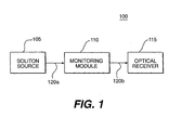
- Fig. 1 is a block diagram illustrating an operating environment for an embodiment of the present invention.
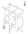
- Fig. 2 graphically illustrates the growth of a dispersive-wave between adjacent soliton pulses as they propagate within the optical transmission system of Fig. 1.
- Fig. 3 illustrates a monitoring and feedback portion of the optical transmission system of Fig. 1 in more detail.
- Fig. 4 illustrates steps from an illustrative method for monitoring transmission performance of soliton pulses in accordance with an embodiment of the present invention.
- an optical transmission system 100 that transmits soliton pulses from an optical source to a receiver.
- the optical transmission system 100 includes a soliton source 105, at least one monitoring module 110 and an optical receiver 115.
- Optical fiber 120a is used within optical transmission system 100 to link soliton source 105 to monitoring module 110.
- optical fiber 120b is used to link monitoring module 110 to optical receiver 115.
- Soliton source 105 is capable of generating a stream or train of soliton pulses, preferably at a relatively high data rate, such as 10 Gbit/s.
- the soliton pulses generated by soliton source 105 are injected into fiber 120a leading to monitoring module 110.
- soliton source 105 may include multiple transmissions or conversion devices for transmitting a plurality of channels in a soliton wavelength-division-multiplexing system for apparatus 100.
- monitoring module 110 monitors transmission performance of the soliton pulses and adjusts characteristics of the soliton-pulse train in order to improve or optimize soliton transmission performance. More particularly, monitoring module 110 detects and monitors a dispersive-wave between each of the adjacent soliton pulses. Additionally, monitoring module 110 determines the relative difference or ratio between a detected energy level of the soliton pulses and a detected energy level of the dispersive wave. The relative difference or ratio is an indication of the transmission performance of the soliton pulses.
- monitoring module 110 is also able to use this indication of transmission performance to adjust, alter or optimize characteristics of the soliton pulses as they propagate through monitoring module 110 toward optical receiver 115.
- optical transmission system 100 can advantageously operate over fiber optic links, such as conventional Inter Exchange Carrier (IEC) fiber links, which have varying or unknown values of link dispersion, fiber loss and length. Additional features of monitoring module 110 will be described below in more detail with regard to Fig. 3.
- IEC Inter Exchange Carrier
- monitoring module 110 is directly connected to optical receiver 115 without the need for fiber 120b. Additionally, it is contemplated that other embodiments of the present invention may also include one or more optical amplifiers (not shown) or one or more adjustable dispersion compensation devices (not shown), collectively referred to as control devices, as part of fiber 120a. In this manner, monitoring module 110 may provide feedback to one or more of such control devices and soliton source 105 in order to monitor and optimize the soliton-pulse transmission performance.
- optical transmission system 100 illustrated in Fig. 1 shows only one monitoring module 100
- other embodiments of the present invention may use more than one monitoring module 100 periodically spread along the fiber route.
- the monitoring modules may be chained together in a series utilizing sections of optical fiber. In such a series configuration, multiple monitoring modules provide the ability to monitor and adaptively improve or optimise the soliton pulse transmission performance at multiple points between soliton source 105 and optical receiver 115 and decrease soliton-dispersive wave interactions.
- FIG. 2 is a diagram illustrating a pair of illustrative adjacent soliton pulses within a series of soliton pulses as the pulses propagate down an optical fiber.
- adjacent soliton pulses 200 are illustrated as they propagate in direction Z within an optical fiber, such as fiber 120a from Fig. 1. More particularly, the pair of adjacent soliton pulses 200 are illustrated at three different transmission distances (Z 1 , Z 2 , and Z 3 ) from a light source as adjacent soliton pulses 200 propagate downstream within the optical fiber in direction Z away from the light source.
- adjacent soliton pulses 200 appear to have acceptable transmission performance because there is no dispersive energy between adjacent soliton pulses 200.
- the first transmission distance Z 1 may be representative of the point where adjacent soliton pulses 200 have just been injected into fiber 120a at soliton source 105.
- next transmission distance Z 2 the same adjacent soliton pulses 200 appear.
- this next transmission distance Z 2 may be representative of the point where adjacent soliton pulses 200 are propagating in fiber 120a mid-way between soliton source 105 and monitoring module 110.
- some dispersive non-solitonic energy appears between adjacent soliton pulses 200.
- the dispersive non-solitonic energy is excess pulse energy that no longer fits within the soliton solution to the nonlinear Schrodinger wave equation. According to the nonlinear Schrodinger wave equation as described in the Franco article, such excess energy is shed from the soliton-pulse as the soliton-pulse continually reshapes itself during propagation. Thus, the dispersive non-solitonic energy appears as a dispersive-wave 205 between adjacent soliton pulses 200.
- this final transmission distance Z 3 may be representative of the point where adjacent soliton pulses 200 have propagated through fiber 120a and are about to enter monitoring module 110. Due to the transmission distance over which adjacent soliton pulses 200 traveled, additional dispersive non-solitonic energy has fallen out of the solitons 200 and into dispersive-wave 205. As shown in Fig. 2, the energy level of dispersive-wave 205 at transmission distance Z 3 has increased relative to the energy level of adjacent soliton pulses 200.
- FIG. 3 is a more detailed block diagram of such an optical transmission system, which includes an apparatus for monitoring transmission performance of soliton pulses consistent with an embodiment of the present invention.
- an embodiment consistent with the present invention includes soliton source 105, which provides a soliton-pulse stream to monitoring module 110.
- monitoring module 110 includes a control device 305 optically responsive to a series of detection and monitoring components.
- Control device 305 is an optical or electro-optical device capable of altering one or more characteristics of the soliton pulses in order to improve transmission performance of the pulses. For example, such characteristics may include the power level of the soliton pulses, the dispersion of the soliton pulses or the pulse shape of the soliton pulses.
- control device 305 may be an optical amplifier with an adjustable gain or an adjustable dispersion compensator.
- An example of an adjustable dispersion compensator suitable for use in an illustrative embodiment of the present invention is a conventional Bragg grating.
- Those skilled in the art will know of various other conventional devices suitable for adjusting the dispersion of a soliton pulse.
- the detection and monitoring components include a series of optical splitters 310a-c, a gating device 315, a timing circuit 320, several detectors 325a-b and a feedback device 330.
- the soliton pulses pass through control device 305, the soliton-pulse stream is sampled or split several ways by splitters 310a-c in order to monitor the transmission performance of the soliton pulses.
- Splitters 310a-c provide the soliton pulses to a pulse input of gating device 315, timing circuit 320 and one of the detectors 325a.
- the detector 325a measures an energy level of the soliton pulses.
- the detector 325a is a low bandwidth photodiode used for measuring average optical power.
- the measured energy level may include the energy of the soliton pulses along with the energy of the dispersive wave as an average optical power of the stream of soliton pulses.
- timing circuit 320 Upon receiving the soliton pulses, timing circuit 320 (called a clock recovery circuit in some embodiments of the present invention) extracts a gating signal from the soliton pulses.
- the gating signal provides an indication of the time period between adjacent soliton pulses 200 during which dispersive-wave 205 may appear.
- the gating signal is implemented as a 10 GHz clock signal extracted from a 10 Gbit/sec soliton pulse stream.
- the gating signal is provided to a timing input of gating device 315 as a trigger.
- the gating signal is out of phase (preferably by approximately 180 degrees) with the incoming soliton pulses.
- gating device 315 may be triggered by the gating signal between adjacent soliton pulses so that the "through" state of the gating device 315 is typically 180 degrees out of phase with the incoming soliton pulses. This allows gating device 315 to provide access to dispersive-wave 205 between adjacent soliton pulses 200.
- gating device 315 is implemented as an optical gating device such as an electro-absorptive modulator, an electro-optic modulator or a nonlinear optical loop mirror.
- the gating device is a Model Number 28976 Lithium Niobate (LiNbO 3 ) integrated electro-optic modulator manufactured by Pirelli Corporation.
- Other embodiments of the present invention may use electro-absorptive modulators manufactured by Alcatel Corporation.
- dispersive-wave energy will appear at a detected output of gating device 315.
- the dispersive-wave or a signal provided by gating device 315 representative of the dispersive-wave energy is then detected by detector 325b.
- detector 325b is a low bandwidth photodiode. In this manner, the energy level of dispersive-wave 205 may be monitored for average power level or instantaneous power level.
- Detectors 325a-b are each connected to feedback device 330 and provide signals indicative of the energy of the soliton pulses and of the detected energy of the dispersive-wave 205, respectively. While, the energy of the soliton pulses measured with detector 325a includes the energy of dispersive-wave 205, the energy measured by detector 325a may also be the energy of just the soliton pulses themselves. In any event, feedback device 330 compares the respective energy levels and determines the difference or a ratio between the energy level of the dispersive-wave to the energy level of the soliton pulses. This comparison, difference or ratio provides an advantageous indication of soliton-pulse transmission performance. In other words, comparing these energy levels gives an indication of the quality (or degradation) of soliton-pulse fidelity.
- feedback device 330 is a processing device such as a conventional microprocessor or conventional microcontroller.
- feedback device 330 may also be implemented using discrete logical circuit components or analog control circuitry depending upon particular design and cost considerations in any embodiment of the present invention.
- control device 305 may be advantageously provided back to control device 305 (or multiple control devices) as telemetry from a feedback output of feedback device 330.
- the information may be generally used by control device 305 to alter a characteristic of the soliton pulses. More particularly, the value of the feedback signal allows control device 305 to appropriately alter or optimize the transmission performance of the soliton pulses.
- an optical amplifier with gain control, a pulse compressor/expander, or an adjustable dispersion compensator may accomplish this by altering one or a combination of a power level of the soliton pulses, a pulse shape of the soliton pulses, or a dispersion characteristic of the soliton pulses.
- optical transmission system 100 can be adaptive and robust to deal with varying or unknown values of fiber link dispersion, fiber loss, and fiber length.
- monitoring module 110 is desired within optical transmission system 100, those skilled in the art can appreciate that such multiple monitoring modules 110 as described herein would provide an additional level of adaptability and robustness to optical transmission system 100.
- the feedback signal may be provided all the way back to soliton source 105 at a provisioning stage of the optical transmission system 100.
- soliton source 105 may also be considered a control device that alters characteristics of the soliton pulses in order to improve or optimize soliton-pulse transmission performance.
- the control device may be adjusted so that optical transmission system 100 operates just above an optimum transmission performance level for a fundamental soliton.
- monitoring module 110 may detect and monitor a small but finite energy level associated with dispersive-wave 205.
- the dispersive wave's energy level may be large enough to detect and monitor using an embodiment of the present invention as described above, but not so large that the dispersive wave's energy substantially affects the soliton transmission performance.
- Fig. 4 is a flow diagram illustrating steps from a method for monitoring transmission performance of soliton pulses consistent with an embodiment of the present invention.
- the method 400 begins at step 405 where an energy level of the soliton pulses is measured.
- detector 325a detects the energy level of the soliton pulses.
- the detected energy level of the soliton pulses includes the average energy level of both the soliton pulses and the dispersive wave.
- the soliton pulses are applied to a gating device, such as gating device 315.
- a gating device such as gating device 315.
- dispersive-wave energy is essentially gated between adjacent soliton pulses in the pulse stream during step 415.
- the soliton pulses are gated to reveal or access a dispersive-wave between adjacent soliton pulses. Accessing the dispersive-wave is typically accomplished by triggering the gating device with a gating signal after one of the soliton pulses has passed but before the next soliton-pulse has arrived at the gating device.
- the gating device typically enters a "through” state and essentially allows the dispersive-wave "through” to be monitored.
- the energy level of the dispersive-wave is monitored.
- the dispersive-wave energy is monitored using another detector 325b in combination with feedback device 330.
- the energy level of the dispersive-wave is compared to the energy level of the soliton pulses themselves.
- the relative difference in energy levels or a ratio of the different energy levels indicates the transmission performance of the soliton pulses as they have propagated.
- the indication of soliton-pulse transmission performance is advantageous because it permits adaptation and handling of fiber links with unknown loss, dispersion, and length characteristics with an optical transmission system.
- a feedback signal is generated that relates to the indication of soliton-pulse transmission performance. More particularly stated, the value of the feedback signal represents the indication of transmission performance.
- the feedback signal is provided as telemetry to a control device, such as control device 305 in Fig. 3, as described in step 435. By doing so, the control device can then complete the adaptive feedback loop and alter the soliton pulses to improve or optimize transmission performance as soliton pulses pass through the control device based upon the feedback signal (i.e ., the indication of soliton-pulse transmission performance) at step 440.
- an illustrative embodiment of the present invention is part of optical transmission system 100 and includes gating device 315, feedback device 330 and control device 305.
- Soliton pulses are received by gating 315, which then detects and monitors a dispersive-wave 205 between adjacent soliton pulses 200 with the assistance of timing circuit 320.
- Timing circuit 320 provides a gating signal offset in phase (typically approximately 180 degrees offset in phase) from the soliton pulses incident to gating device 315 in order to trigger gating device 315.
- Triggering gating device 315 allows the dispersive-wave 205 to be accessed and monitored between adjacent soliton pulses 200.
- Feedback device 330 uses detectors 325a-b and processing circuitry, measures the energy of the soliton pulses and the energy of dispersive-wave 205. Feedback device 330 then compares the relative energy levels or, more particularly stated, determines a ratio of the energy levels as an indication of soliton-pulse transmission performance. This indication is then fed back to control device 305 as a feedback signal in order for control device 305 to appropriately adjust characteristics of the soliton pulses and improve or optimize transmission performance.
- monitoring module depicted in the figures is intended to be illustrative of preferred embodiments.
- the precise gating and feedback structure may readily be altered by one of ordinary skill in the art.
Landscapes
- Physics & Mathematics (AREA)
- Electromagnetism (AREA)
- Engineering & Computer Science (AREA)
- Computer Networks & Wireless Communication (AREA)
- Signal Processing (AREA)
- Optical Communication System (AREA)
- Optical Modulation, Optical Deflection, Nonlinear Optics, Optical Demodulation, Optical Logic Elements (AREA)
- Radar Systems Or Details Thereof (AREA)
- Magnetic Resonance Imaging Apparatus (AREA)
Applications Claiming Priority (2)
| Application Number | Priority Date | Filing Date | Title |
|---|---|---|---|
| US132014 | 1998-08-10 | ||
| US09/132,014 US6259542B1 (en) | 1998-08-10 | 1998-08-10 | Method and apparatus for monitoring dispersive-wave energy to indicate and optimize soliton transmission performance |
Publications (2)
| Publication Number | Publication Date |
|---|---|
| EP0980155A1 EP0980155A1 (en) | 2000-02-16 |
| EP0980155B1 true EP0980155B1 (en) | 2003-10-29 |
Family
ID=22452041
Family Applications (1)
| Application Number | Title | Priority Date | Filing Date |
|---|---|---|---|
| EP99306259A Expired - Lifetime EP0980155B1 (en) | 1998-08-10 | 1999-08-06 | Method and apparatus for monitoring dispersive-wave energy to optimize soliton transmission performance |
Country Status (9)
| Country | Link |
|---|---|
| US (1) | US6259542B1 (da) |
| EP (1) | EP0980155B1 (da) |
| JP (1) | JP2000089265A (da) |
| AT (1) | ATE253272T1 (da) |
| AU (1) | AU4349299A (da) |
| BR (1) | BR9903613A (da) |
| CA (1) | CA2279605A1 (da) |
| DE (1) | DE69912366T2 (da) |
| DK (1) | DK0980155T3 (da) |
Families Citing this family (8)
| Publication number | Priority date | Publication date | Assignee | Title |
|---|---|---|---|---|
| US6577413B1 (en) * | 2000-03-03 | 2003-06-10 | Pirelli Cavi E Sistemi S.P.A. | Method and apparatus for polarization multiplexing and demultiplexing optical tributary signals |
| US7099597B2 (en) | 2000-08-25 | 2006-08-29 | Pts Corporation | Method of adaptive signal degradation compensation |
| US6961522B1 (en) | 2000-11-22 | 2005-11-01 | Cisco Technology, Inc. | Automatic raman gain and tilt control for ultra-long-distance dense WDM optical communication system |
| EP1281250B1 (en) * | 2001-03-15 | 2011-05-25 | FITEL USA CORPORATION, (A Delaware Corporation) | Nonlinear device comprising a spectrally broadening fiber |
| US6941079B1 (en) * | 2001-05-24 | 2005-09-06 | Cisco Technology, Inc. | Optical demultiplexer with multi-channel power control and tilt compensation |
| US7840145B2 (en) * | 2003-06-27 | 2010-11-23 | The Boeing Company | Apparatus and methods for noise-feedback controlled optical systems |
| EP2802043A1 (en) * | 2013-05-08 | 2014-11-12 | Max-Planck-Gesellschaft zur Förderung der Wissenschaften e.V. | Method and light pulse source for generating soliton light pulses |
| US10241230B2 (en) * | 2015-06-26 | 2019-03-26 | Halliburton Energy Services, Inc. | Downhole sensing using solitons in optical fiber |
Family Cites Families (11)
| Publication number | Priority date | Publication date | Assignee | Title |
|---|---|---|---|---|
| US5035481A (en) | 1990-08-23 | 1991-07-30 | At&T Bell Laboratories | Long distance soliton lightwave communication system |
| JP2701189B2 (ja) | 1992-09-25 | 1998-01-21 | 国際電信電話株式会社 | 光通信伝送路 |
| JP3419510B2 (ja) * | 1992-10-16 | 2003-06-23 | 富士通株式会社 | 波長分散を補償した光通信システム及び該システムに適用可能な位相共役光発生装置 |
| FR2700901B1 (fr) | 1993-01-28 | 1995-02-24 | Alcatel Nv | Système et procédé de transmission à solitons. |
| BE1007217A3 (nl) | 1993-06-11 | 1995-04-25 | Philips Electronics Nv | Optisch soliton transmissiesysteem. |
| JP3028906B2 (ja) | 1994-01-27 | 2000-04-04 | ケイディディ株式会社 | ソリトン光通信システム及びその光送信装置と光受信装置 |
| GB2286898B (en) | 1994-02-26 | 1997-08-20 | Northern Telecom Ltd | Chirped distributed Bragg grating optical fibre filters on flexible plates |
| US5513194A (en) | 1994-06-30 | 1996-04-30 | Massachusetts Institute Of Technology | Stretched-pulse fiber laser |
| US5579428A (en) | 1995-06-07 | 1996-11-26 | Corning Incorporated | Solitons in dispersion flattened waveguide |
| US5767998A (en) | 1995-09-13 | 1998-06-16 | Research Development Corporation Of Japan | Wavelength-division multiplexed communication system utilizing optical solitons |
| US5737460A (en) | 1995-12-29 | 1998-04-07 | Lucent Technologies Inc. | Applications of solitons in transmission systems employing high launch powers |
-
1998
- 1998-08-10 US US09/132,014 patent/US6259542B1/en not_active Expired - Lifetime
-
1999
- 1999-08-04 CA CA002279605A patent/CA2279605A1/en not_active Abandoned
- 1999-08-06 EP EP99306259A patent/EP0980155B1/en not_active Expired - Lifetime
- 1999-08-06 DK DK99306259T patent/DK0980155T3/da active
- 1999-08-06 AT AT99306259T patent/ATE253272T1/de not_active IP Right Cessation
- 1999-08-06 DE DE69912366T patent/DE69912366T2/de not_active Expired - Lifetime
- 1999-08-10 AU AU43492/99A patent/AU4349299A/en not_active Abandoned
- 1999-08-10 BR BR9903613-4A patent/BR9903613A/pt not_active Application Discontinuation
- 1999-08-10 JP JP22647099A patent/JP2000089265A/ja active Pending
Also Published As
| Publication number | Publication date |
|---|---|
| ATE253272T1 (de) | 2003-11-15 |
| CA2279605A1 (en) | 2000-02-10 |
| AU4349299A (en) | 2000-03-02 |
| DE69912366D1 (de) | 2003-12-04 |
| DE69912366T2 (de) | 2004-08-12 |
| EP0980155A1 (en) | 2000-02-16 |
| JP2000089265A (ja) | 2000-03-31 |
| US6259542B1 (en) | 2001-07-10 |
| BR9903613A (pt) | 2000-08-29 |
| DK0980155T3 (da) | 2004-03-15 |
Similar Documents
| Publication | Publication Date | Title |
|---|---|---|
| EP0792069B1 (en) | Cancellation of distortion components in a fiber optic link with feed-forward linearization | |
| Mohrdiek et al. | 10-Gb/s standard fiber transmission using directly modulated 1.55-μm quantum-well DFB lasers | |
| US6075634A (en) | Gigabit data rate extended range fiber optic communication system and transponder therefor | |
| US6661974B1 (en) | Optical transmitter and optical transmission system | |
| US7389049B2 (en) | Chromatic dispersion compensation controlling system | |
| US6570691B1 (en) | Optical transmission system using in-line amplifiers | |
| US20060051017A1 (en) | Optical fiber transmission system with increased effective modal bandwidth transmission | |
| US20080212962A1 (en) | Chirp measurement method, chirp measurement apparatus and their application | |
| US5966228A (en) | Optical transmission system and optical repeater | |
| US6456411B1 (en) | Method of setting signal wavelength in optical transmission system | |
| EP0980155B1 (en) | Method and apparatus for monitoring dispersive-wave energy to optimize soliton transmission performance | |
| US5852700A (en) | Method and device for the generation of ultrashort optical pulses | |
| US20040076373A1 (en) | Optical pulse regenerating transmission lines | |
| EP1566002B1 (en) | Optical communication system | |
| Ali et al. | Simulation and performance analysis of a fiber communication system based on FBG as dispersion compensator | |
| Onidare et al. | Optical dispersion compensation using different modulation formats | |
| US6583905B1 (en) | Apparatus and method for reducing SPM/GVD in optical systems | |
| EP0963066B1 (en) | Apparatus and method for reducing SPM/GVD in optical systems | |
| Rahman et al. | Study and design of A high capacity fiber‐optic communication link by analyzing and comparing different dispersion techniques using DCF | |
| EP0598387B1 (en) | Optical transmission line and distortion reduction technique | |
| Boiyo et al. | An integrated OADM based on Bragg trans-reflectance in 1550 nm VCSEL optical fibre access networks | |
| Odeh | COMPARING DISPERSION COMPENSATION METHODS FOR 120 GB/S OPTICAL TRANSMISSION: PRE, POST, AND SYMMETRICAL SCHEMES | |
| Ramachandran | Higher-order-mode dispersion compensation for broadband dispersion and non-linearity management in transmission systems | |
| Lin et al. | Spectral filtering of multiple directly modulated channels for WDM access networks by using an FP etalon | |
| JP3508898B2 (ja) | 光ソリトン通信伝送路 |
Legal Events
| Date | Code | Title | Description |
|---|---|---|---|
| PUAI | Public reference made under article 153(3) epc to a published international application that has entered the european phase |
Free format text: ORIGINAL CODE: 0009012 |
|
| AK | Designated contracting states |
Kind code of ref document: A1 Designated state(s): AT BE CH CY DE DK ES FI FR GB GR IE IT LI LU MC NL PT SE |
|
| AX | Request for extension of the european patent |
Free format text: AL;LT;LV;MK;RO;SI |
|
| RAP1 | Party data changed (applicant data changed or rights of an application transferred) |
Owner name: PIRELLI CAVI E SISTEMI S.P.A. |
|
| 17P | Request for examination filed |
Effective date: 20000814 |
|
| AKX | Designation fees paid |
Free format text: AT BE CH CY DE DK ES FI FR GB GR IE IT LI LU MC NL PT SE |
|
| 17Q | First examination report despatched |
Effective date: 20001110 |
|
| GRAG | Despatch of communication of intention to grant |
Free format text: ORIGINAL CODE: EPIDOS AGRA |
|
| GRAG | Despatch of communication of intention to grant |
Free format text: ORIGINAL CODE: EPIDOS AGRA |
|
| GRAG | Despatch of communication of intention to grant |
Free format text: ORIGINAL CODE: EPIDOS AGRA |
|
| GRAG | Despatch of communication of intention to grant |
Free format text: ORIGINAL CODE: EPIDOS AGRA |
|
| GRAH | Despatch of communication of intention to grant a patent |
Free format text: ORIGINAL CODE: EPIDOS IGRA |
|
| GRAS | Grant fee paid |
Free format text: ORIGINAL CODE: EPIDOSNIGR3 |
|
| RAP1 | Party data changed (applicant data changed or rights of an application transferred) |
Owner name: CISCO PHOTONICS ITALY SRL |
|
| GRAA | (expected) grant |
Free format text: ORIGINAL CODE: 0009210 |
|
| AK | Designated contracting states |
Kind code of ref document: B1 Designated state(s): AT BE CH CY DE DK ES FI FR GB GR IE IT LI LU MC NL PT SE |
|
| PG25 | Lapsed in a contracting state [announced via postgrant information from national office to epo] |
Ref country code: LI Free format text: LAPSE BECAUSE OF FAILURE TO SUBMIT A TRANSLATION OF THE DESCRIPTION OR TO PAY THE FEE WITHIN THE PRESCRIBED TIME-LIMIT Effective date: 20031029 Ref country code: FI Free format text: LAPSE BECAUSE OF FAILURE TO SUBMIT A TRANSLATION OF THE DESCRIPTION OR TO PAY THE FEE WITHIN THE PRESCRIBED TIME-LIMIT Effective date: 20031029 Ref country code: CY Free format text: LAPSE BECAUSE OF FAILURE TO SUBMIT A TRANSLATION OF THE DESCRIPTION OR TO PAY THE FEE WITHIN THE PRESCRIBED TIME-LIMIT Effective date: 20031029 Ref country code: CH Free format text: LAPSE BECAUSE OF FAILURE TO SUBMIT A TRANSLATION OF THE DESCRIPTION OR TO PAY THE FEE WITHIN THE PRESCRIBED TIME-LIMIT Effective date: 20031029 Ref country code: BE Free format text: LAPSE BECAUSE OF FAILURE TO SUBMIT A TRANSLATION OF THE DESCRIPTION OR TO PAY THE FEE WITHIN THE PRESCRIBED TIME-LIMIT Effective date: 20031029 Ref country code: AT Free format text: LAPSE BECAUSE OF FAILURE TO SUBMIT A TRANSLATION OF THE DESCRIPTION OR TO PAY THE FEE WITHIN THE PRESCRIBED TIME-LIMIT Effective date: 20031029 |
|
| REG | Reference to a national code |
Ref country code: GB Ref legal event code: FG4D |
|
| REG | Reference to a national code |
Ref country code: CH Ref legal event code: EP |
|
| REG | Reference to a national code |
Ref country code: IE Ref legal event code: FG4D |
|
| REF | Corresponds to: |
Ref document number: 69912366 Country of ref document: DE Date of ref document: 20031204 Kind code of ref document: P |
|
| PG25 | Lapsed in a contracting state [announced via postgrant information from national office to epo] |
Ref country code: SE Free format text: LAPSE BECAUSE OF FAILURE TO SUBMIT A TRANSLATION OF THE DESCRIPTION OR TO PAY THE FEE WITHIN THE PRESCRIBED TIME-LIMIT Effective date: 20040129 Ref country code: GR Free format text: LAPSE BECAUSE OF FAILURE TO SUBMIT A TRANSLATION OF THE DESCRIPTION OR TO PAY THE FEE WITHIN THE PRESCRIBED TIME-LIMIT Effective date: 20040129 |
|
| PG25 | Lapsed in a contracting state [announced via postgrant information from national office to epo] |
Ref country code: ES Free format text: LAPSE BECAUSE OF FAILURE TO SUBMIT A TRANSLATION OF THE DESCRIPTION OR TO PAY THE FEE WITHIN THE PRESCRIBED TIME-LIMIT Effective date: 20040209 |
|
| REG | Reference to a national code |
Ref country code: DK Ref legal event code: T3 |
|
| REG | Reference to a national code |
Ref country code: CH Ref legal event code: PL |
|
| ET | Fr: translation filed | ||
| PG25 | Lapsed in a contracting state [announced via postgrant information from national office to epo] |
Ref country code: LU Free format text: LAPSE BECAUSE OF NON-PAYMENT OF DUE FEES Effective date: 20040806 Ref country code: IE Free format text: LAPSE BECAUSE OF NON-PAYMENT OF DUE FEES Effective date: 20040806 |
|
| PG25 | Lapsed in a contracting state [announced via postgrant information from national office to epo] |
Ref country code: MC Free format text: LAPSE BECAUSE OF NON-PAYMENT OF DUE FEES Effective date: 20040831 |
|
| PLBE | No opposition filed within time limit |
Free format text: ORIGINAL CODE: 0009261 |
|
| STAA | Information on the status of an ep patent application or granted ep patent |
Free format text: STATUS: NO OPPOSITION FILED WITHIN TIME LIMIT |
|
| 26N | No opposition filed |
Effective date: 20040730 |
|
| REG | Reference to a national code |
Ref country code: IE Ref legal event code: MM4A |
|
| PG25 | Lapsed in a contracting state [announced via postgrant information from national office to epo] |
Ref country code: PT Free format text: LAPSE BECAUSE OF NON-PAYMENT OF DUE FEES Effective date: 20040329 |
|
| REG | Reference to a national code |
Ref country code: FR Ref legal event code: PLFP Year of fee payment: 17 |
|
| PGFP | Annual fee paid to national office [announced via postgrant information from national office to epo] |
Ref country code: GB Payment date: 20150827 Year of fee payment: 17 Ref country code: DE Payment date: 20150827 Year of fee payment: 17 Ref country code: DK Payment date: 20150825 Year of fee payment: 17 |
|
| PGFP | Annual fee paid to national office [announced via postgrant information from national office to epo] |
Ref country code: FR Payment date: 20150817 Year of fee payment: 17 |
|
| PGFP | Annual fee paid to national office [announced via postgrant information from national office to epo] |
Ref country code: IT Payment date: 20150825 Year of fee payment: 17 |
|
| REG | Reference to a national code |
Ref country code: DE Ref legal event code: R119 Ref document number: 69912366 Country of ref document: DE |
|
| REG | Reference to a national code |
Ref country code: DK Ref legal event code: EBP Effective date: 20160831 |
|
| GBPC | Gb: european patent ceased through non-payment of renewal fee |
Effective date: 20160806 |
|
| REG | Reference to a national code |
Ref country code: FR Ref legal event code: ST Effective date: 20170428 |
|
| PG25 | Lapsed in a contracting state [announced via postgrant information from national office to epo] |
Ref country code: GB Free format text: LAPSE BECAUSE OF NON-PAYMENT OF DUE FEES Effective date: 20160806 Ref country code: DE Free format text: LAPSE BECAUSE OF NON-PAYMENT OF DUE FEES Effective date: 20170301 Ref country code: DK Free format text: LAPSE BECAUSE OF NON-PAYMENT OF DUE FEES Effective date: 20160831 Ref country code: FR Free format text: LAPSE BECAUSE OF NON-PAYMENT OF DUE FEES Effective date: 20160831 |
|
| PG25 | Lapsed in a contracting state [announced via postgrant information from national office to epo] |
Ref country code: IT Free format text: LAPSE BECAUSE OF NON-PAYMENT OF DUE FEES Effective date: 20160806 |
|
| PGFP | Annual fee paid to national office [announced via postgrant information from national office to epo] |
Ref country code: NL Payment date: 20180826 Year of fee payment: 20 |
|
| REG | Reference to a national code |
Ref country code: NL Ref legal event code: MK Effective date: 20190805 |