EP0979967A2 - Schlauchhalter - Google Patents
Schlauchhalter Download PDFInfo
- Publication number
- EP0979967A2 EP0979967A2 EP99114265A EP99114265A EP0979967A2 EP 0979967 A2 EP0979967 A2 EP 0979967A2 EP 99114265 A EP99114265 A EP 99114265A EP 99114265 A EP99114265 A EP 99114265A EP 0979967 A2 EP0979967 A2 EP 0979967A2
- Authority
- EP
- European Patent Office
- Prior art keywords
- hose
- hose holder
- lever
- robot
- holder
- Prior art date
- Legal status (The legal status is an assumption and is not a legal conclusion. Google has not performed a legal analysis and makes no representation as to the accuracy of the status listed.)
- Granted
Links
Images


Classifications
-
- F—MECHANICAL ENGINEERING; LIGHTING; HEATING; WEAPONS; BLASTING
- F16—ENGINEERING ELEMENTS AND UNITS; GENERAL MEASURES FOR PRODUCING AND MAINTAINING EFFECTIVE FUNCTIONING OF MACHINES OR INSTALLATIONS; THERMAL INSULATION IN GENERAL
- F16L—PIPES; JOINTS OR FITTINGS FOR PIPES; SUPPORTS FOR PIPES, CABLES OR PROTECTIVE TUBING; MEANS FOR THERMAL INSULATION IN GENERAL
- F16L3/00—Supports for pipes, cables or protective tubing, e.g. hangers, holders, clamps, cleats, clips, brackets
- F16L3/08—Supports for pipes, cables or protective tubing, e.g. hangers, holders, clamps, cleats, clips, brackets substantially surrounding the pipe, cable or protective tubing
- F16L3/10—Supports for pipes, cables or protective tubing, e.g. hangers, holders, clamps, cleats, clips, brackets substantially surrounding the pipe, cable or protective tubing divided, i.e. with two or more members engaging the pipe, cable or protective tubing
- F16L3/1075—Supports for pipes, cables or protective tubing, e.g. hangers, holders, clamps, cleats, clips, brackets substantially surrounding the pipe, cable or protective tubing divided, i.e. with two or more members engaging the pipe, cable or protective tubing with two members, the two members being joined with a hinge on one side and fastened together on the other side
-
- H—ELECTRICITY
- H02—GENERATION; CONVERSION OR DISTRIBUTION OF ELECTRIC POWER
- H02G—INSTALLATION OF ELECTRIC CABLES OR LINES, OR OF COMBINED OPTICAL AND ELECTRIC CABLES OR LINES
- H02G3/00—Installations of electric cables or lines or protective tubing therefor in or on buildings, equivalent structures or vehicles
- H02G3/02—Details
- H02G3/04—Protective tubing or conduits, e.g. cable ladders or cable troughs
- H02G3/0462—Tubings, i.e. having a closed section
- H02G3/0475—Tubings, i.e. having a closed section formed by a succession of articulated units
-
- H—ELECTRICITY
- H02—GENERATION; CONVERSION OR DISTRIBUTION OF ELECTRIC POWER
- H02G—INSTALLATION OF ELECTRIC CABLES OR LINES, OR OF COMBINED OPTICAL AND ELECTRIC CABLES OR LINES
- H02G3/00—Installations of electric cables or lines or protective tubing therefor in or on buildings, equivalent structures or vehicles
- H02G3/02—Details
- H02G3/06—Joints for connecting lengths of protective tubing or channels, to each other or to casings, e.g. to distribution boxes; Ensuring electrical continuity in the joint
-
- H—ELECTRICITY
- H02—GENERATION; CONVERSION OR DISTRIBUTION OF ELECTRIC POWER
- H02G—INSTALLATION OF ELECTRIC CABLES OR LINES, OR OF COMBINED OPTICAL AND ELECTRIC CABLES OR LINES
- H02G3/00—Installations of electric cables or lines or protective tubing therefor in or on buildings, equivalent structures or vehicles
- H02G3/26—Installations of cables, lines, or separate protective tubing therefor directly on or in walls, ceilings, or floors
-
- Y—GENERAL TAGGING OF NEW TECHNOLOGICAL DEVELOPMENTS; GENERAL TAGGING OF CROSS-SECTIONAL TECHNOLOGIES SPANNING OVER SEVERAL SECTIONS OF THE IPC; TECHNICAL SUBJECTS COVERED BY FORMER USPC CROSS-REFERENCE ART COLLECTIONS [XRACs] AND DIGESTS
- Y10—TECHNICAL SUBJECTS COVERED BY FORMER USPC
- Y10T—TECHNICAL SUBJECTS COVERED BY FORMER US CLASSIFICATION
- Y10T24/00—Buckles, buttons, clasps, etc.
- Y10T24/14—Bale and package ties, hose clamps
- Y10T24/1412—Bale and package ties, hose clamps with tighteners
- Y10T24/1418—Self-locking [dead center or snap action]
Definitions
- the invention relates to a hose holder, in particular for holding a protective hose for cables on one Robot, with two articulated and over one lever with a spring clip, lockable Half shells.
- Such hose holders are used in particular on robots provided to protective tubes for outside of the robot to keep guided electrical cables axially movable.
- the hose holder are by means of an open, in Cut a trapezoidal base on one Holder, such as part of the robot, an arm or one Swing arm, attached, with the free ends of the trapezoidal Base usually in one piece with the actual, trumpet-like towards its free ends opening hose holder are connected. Since the the hose lead-through is trumpet-like opening walls of the hose holder elastic and in the rest of two interconnected half shells are formed, relative movements of the hose holder towards the part of the robot holding it, the parallelogram-like movements of the base of the hose holder. Through such movements and the dynamic acting on the hose holder Forces can easily damage and break the same occur.
- the invention is therefore based on the object Avoiding the aforementioned disadvantages of a hose holder of the generic type to further develop that in particular an unintentional opening of the Hose holder is avoided.
- the Hose holder secure, firm and stable on his him holding part can be determined.
- the stated task is performed in one Hose holder of the type mentioned solved, which is characterized in that on both sides of the lever radially extending protective ribs are formed, the the peripheral contour of the lever in its closed position cover.
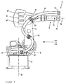
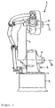
- the robot 1 of FIG. 1 has a fixed to the ground connected base 2 on which the vertical A-axis rotatable robot base 3, the "carousel", located. With this is around the vertical B axis a swing arm 6 is pivotally arranged by means of a motor 4. At the base 3 facing away from the free end with it and around the horizontal C-axis as well of the motor 7, a robot arm 8 is arranged pivotably. This carries a robot hand at its front free end 9 11, which in turn has at least one more horizontal D-axis and one perpendicular to it E-axis is pivotable. The pivoting around the latter E-axis can be from one at the rear end of the arm 8 arranged drive motor 11 above itself through the arm 8 extending drive elements take place. More movements a complicated robot hand like a double angle hand or a tool can by further, arranged at the rear end of the arm 8 Motors 11, 11 'also through the arm 8 itself extending drive elements are effected.
- Both the motors and tools must come from the robot base 2 Energy are supplied. This can be done through the robot elements (Swing arm, arm) or on the outside of the Robots are done, which in many cases is more advantageous is. So that the cables to a power supply from Motors and tools are protected, they are one Protective tube 12 surrounded along the outside of the Robot guided and fixed at this point.
- the protective tube 12 is one with Ribs 13 provided hose.
- the hose is on his Provide ends with end pieces 14. He can wear rings 16, and have a compression spring 17, which at Relief with regard to the robot movement in one Starting position brings.
- a spring end bracket 18 is provided as an abutment for the compression spring.
- the hose is fixed at base 3 at the illustrated embodiment by a bulkhead 19, as well as through the length of the hose Clamps 21 and via so-called trumpets 22.
- the wear rings 16 prevent direct chafing and thus damage to the hose on moving Robot parts, such as on swing arm 6, arm 8 and hand 11.
- the Hose holder 22 is used to support and guide the Hose 12 at one or more points on the rocker 6 and arm 8 of the robot.
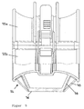
- a hose holder the use of which is shown in FIGS. 1 and 2 is shown and with which the protective tube 12 axially held differently on the robot is in detail in 5 and 6 shown.
- the hose holder 22 opens from its central area trumpet-like towards its free ends. He consists of two half-shells 22a, 22b, which at 23 together are pivoted so that the hose holder opened and with the hose holder open 22 the protective tube is inserted and the tube holder 22 can be closed again.
- a locking mechanism 24 is provided. This instructs the lower half-shell 22b one with a groove-like Undercut provided locking lug 26. In this engages the free web 27 of a spring clip 28, the end facing away from the web 27 in the form of two ends bent relative to its legs a pivot lever 29 is set.
- the spring clip 28 is on the pivot lever 29 eccentric to the bearing axis 31 hinged to the upper half-shell 32, namely between the linkage 31 of the pivot lever 29 and its free actuation end 33.
- the hose holder 22 is on one at its lower Half-shell 22b formed in one piece trapezoidal Base 36 can be fixed on the robot, by means of a Screw fastening via an opening 37.
- the base 36 is with its trapezoid opening legs on the more or less flexible trumpet-like extensions connected to the hose holder.
- Design are in addition to those in legs forming the axes perpendicular to the planes 38 of the trapezoidal base 36 on this axially parallel Directional ribs 39 provided that the base 36 in total stiffen and thus a parallelogram Prevent movement of the base 36 is set.
Landscapes
- Engineering & Computer Science (AREA)
- General Engineering & Computer Science (AREA)
- Architecture (AREA)
- Civil Engineering (AREA)
- Structural Engineering (AREA)
- Mechanical Engineering (AREA)
- Supports For Pipes And Cables (AREA)
- Quick-Acting Or Multi-Walled Pipe Joints (AREA)
- Manipulator (AREA)
Abstract
Description
- Fig. 1
- einen Roboter in Seitenansicht;
- Fig. 2
- den Roboter in Stirnansicht entsprechend dem Pfeil II der Fig. 1;
- Fig. 3
- einen Schutzschlauch für Kabel mit seinen wesentlichen Komponenten;
- Fig. 4
- eine vergrößerte Darstellung eines Ausschnitts des Schutzschlauches der Fig. 3;
- Fig. 5
- eine Seitenansicht des erfindungsgemäßen Schlauchhalters, teilweise geschnitten; und
- Fig. 6
- einen senkrechten Schnitt durch den erfindungsgemäßen Schlauchhalter der Fig. 5.
Claims (2)
- Schlauchhalter, insbesondere zum Halten eines Schutzschlauches für Kabel an einem Roboter, mit zwei aneinander angelenkten und über einen mit einem Federbügel versehenen Hebel schließbaren Halbschalen, dadurch gekennzeichnet, daß beidseitig des Hebels (29) sich radial erstreckende Schutzrippen (36) ausgebildet sind, die die Umfangskontur des Hebels (29) in dessen Schließstellung abdecken.
- Schlauchhalter, insbesondere nach Anspruch 1, gekennzeichnet durch Versteifungsrippen (39) an einem Befestigungssockel (36) zur Befestigung des Schlauchhalters (22).
Applications Claiming Priority (2)
| Application Number | Priority Date | Filing Date | Title |
|---|---|---|---|
| DE29814417U | 1998-08-11 | ||
| DE29814417U DE29814417U1 (de) | 1998-08-11 | 1998-08-11 | Schlauchhalter |
Publications (3)
| Publication Number | Publication Date |
|---|---|
| EP0979967A2 true EP0979967A2 (de) | 2000-02-16 |
| EP0979967A3 EP0979967A3 (de) | 2001-04-04 |
| EP0979967B1 EP0979967B1 (de) | 2002-02-06 |
Family
ID=8061174
Family Applications (1)
| Application Number | Title | Priority Date | Filing Date |
|---|---|---|---|
| EP99114265A Expired - Lifetime EP0979967B1 (de) | 1998-08-11 | 1999-07-28 | Schlauchhalter |
Country Status (4)
| Country | Link |
|---|---|
| US (1) | US6293504B1 (de) |
| EP (1) | EP0979967B1 (de) |
| AT (1) | ATE213058T1 (de) |
| DE (2) | DE29814417U1 (de) |
Cited By (2)
| Publication number | Priority date | Publication date | Assignee | Title |
|---|---|---|---|---|
| WO2003084721A2 (de) * | 2002-04-11 | 2003-10-16 | Kabelschlepp Gmbh | Roboter mit einer leitungsführungseinrichtung |
| CN110549320A (zh) * | 2019-09-26 | 2019-12-10 | 芜湖博士联合智能装备有限公司 | 一种四自由度的混联机器人 |
Families Citing this family (25)
| Publication number | Priority date | Publication date | Assignee | Title |
|---|---|---|---|---|
| US6431018B1 (en) * | 1999-09-09 | 2002-08-13 | Fanuc Ltd. | Guide device for wiring member and/or piping member and robot with guide device |
| JP4099628B2 (ja) * | 2001-10-29 | 2008-06-11 | 株式会社安川電機 | 産業用ロボット |
| US6830075B1 (en) * | 2003-05-09 | 2004-12-14 | Dana Corporation | Hose assembly with integrally molded brake hose bracket |
| JP4493935B2 (ja) * | 2003-05-27 | 2010-06-30 | シャープ株式会社 | 接続装置、画像読取装置および画像形成システム |
| DE102004028577A1 (de) * | 2004-06-15 | 2005-12-29 | Leoni Elocab Gmbh | Führungsvorrichtung zum Führen eines Schlauches |
| JP2006150496A (ja) * | 2004-11-29 | 2006-06-15 | Fanuc Ltd | ロボットの線条体支持装置及び線条体支持装置を備えたロボット |
| DE102005041918A1 (de) * | 2005-09-03 | 2007-03-08 | MAN Nutzfahrzeuge Österreich AG | Leitungshalter |
| US8631734B2 (en) | 2005-11-22 | 2014-01-21 | Robert Bosch Gmbh | Glide movement controller and power miter saw including such controller |
| US20120017736A1 (en) * | 2005-11-22 | 2012-01-26 | Robert Bosch Tool Corporation | Power cord routing system for miter saw with hinge linkage linear guide |
| US8857303B2 (en) | 2005-11-22 | 2014-10-14 | Robert Bosch Gmbh | Locking mechanism for miter saw with hinge linkage linear guide |
| DE102006020928A1 (de) * | 2006-05-05 | 2007-11-08 | Putzmeister Ag | Schlauchhalter, insbesondere für Endschläuche an Betonverteilermasten |
| US9303797B2 (en) | 2006-07-17 | 2016-04-05 | Gates Corporation | Overmolded standoff and method for abrasion routing protection of a hose |
| DE502006006292D1 (de) * | 2006-09-27 | 2010-04-08 | Leoni Protec Cable Systems Gmb | Gungsleitung aufweisenden schlauches |
| DE102007007829A1 (de) | 2007-02-16 | 2008-08-21 | Kuka Roboter Gmbh | Haltevorrichtung für ein Schlauchpaket für Industrieroboter |
| DE102007008985B4 (de) | 2007-02-23 | 2016-09-08 | Kuka Roboter Gmbh | Haltevorrichtung für eine Energiezuführung |
| CN101434071B (zh) * | 2007-11-14 | 2011-02-09 | 中国科学院沈阳自动化研究所 | 一种用于水中活动关节的密封机构 |
| DE102009010953A1 (de) * | 2009-02-27 | 2010-09-02 | Dürr Systems GmbH | Roboter, insbesondere Lackierroboter |
| DE102009043448A1 (de) * | 2009-09-29 | 2011-04-07 | Siemens Aktiengesellschaft | Roboteranordnung |
| CN101940827A (zh) * | 2010-10-14 | 2011-01-12 | 王常灿 | 灭火机器人 |
| US8882057B2 (en) | 2011-09-28 | 2014-11-11 | Cooper B-Line, Inc. | Pipe support |
| US9222602B2 (en) * | 2011-09-28 | 2015-12-29 | Cooper B-Line, Inc. | Pipe support |
| JP5413524B1 (ja) * | 2013-01-17 | 2014-02-12 | 株式会社安川電機 | ロボット |
| US9162550B2 (en) * | 2013-10-08 | 2015-10-20 | Denso International America, Inc. | Wire harness mounting assembly |
| US11040457B2 (en) * | 2014-03-06 | 2021-06-22 | Drossbach North America Incorporated | Cable management system and devices |
| JP6474689B2 (ja) * | 2015-05-29 | 2019-02-27 | アクア株式会社 | 冷蔵庫 |
Citations (5)
| Publication number | Priority date | Publication date | Assignee | Title |
|---|---|---|---|---|
| US1773838A (en) * | 1927-08-10 | 1930-08-26 | Lothar R Zifferer | Pipe hanger |
| FR2376319A1 (fr) * | 1976-12-31 | 1978-07-28 | Outillage Mecanique Ste Paris | Perfectionnements a un collier de serrage |
| US4252289A (en) * | 1978-02-15 | 1981-02-24 | Hilti Aktiengesellschaft | Two-part pipe clip |
| US4705243A (en) * | 1983-10-19 | 1987-11-10 | Kuka Schweissanlangen | System of externally holding and guiding supply lines to moving implements of manipulators |
| FR2689604A1 (fr) * | 1992-04-03 | 1993-10-08 | Aerospatiale | Support de câble universel. |
Family Cites Families (4)
| Publication number | Priority date | Publication date | Assignee | Title |
|---|---|---|---|---|
| US196807A (en) * | 1877-11-06 | Improvement in hose and pipe couplings | ||
| US2122988A (en) * | 1935-05-22 | 1938-07-05 | Westinghouse X Ray Co Inc | Shockproof x-ray tube stand |
| BE664547A (de) * | 1964-05-27 | |||
| US6056245A (en) * | 1996-01-25 | 2000-05-02 | Phillip E. White | Flared cable support for telecommunication system installations |
-
1998
- 1998-08-11 DE DE29814417U patent/DE29814417U1/de not_active Expired - Lifetime
-
1999
- 1999-07-28 DE DE59900817T patent/DE59900817D1/de not_active Expired - Lifetime
- 1999-07-28 AT AT99114265T patent/ATE213058T1/de not_active IP Right Cessation
- 1999-07-28 EP EP99114265A patent/EP0979967B1/de not_active Expired - Lifetime
- 1999-08-10 US US09/371,242 patent/US6293504B1/en not_active Expired - Fee Related
Patent Citations (5)
| Publication number | Priority date | Publication date | Assignee | Title |
|---|---|---|---|---|
| US1773838A (en) * | 1927-08-10 | 1930-08-26 | Lothar R Zifferer | Pipe hanger |
| FR2376319A1 (fr) * | 1976-12-31 | 1978-07-28 | Outillage Mecanique Ste Paris | Perfectionnements a un collier de serrage |
| US4252289A (en) * | 1978-02-15 | 1981-02-24 | Hilti Aktiengesellschaft | Two-part pipe clip |
| US4705243A (en) * | 1983-10-19 | 1987-11-10 | Kuka Schweissanlangen | System of externally holding and guiding supply lines to moving implements of manipulators |
| FR2689604A1 (fr) * | 1992-04-03 | 1993-10-08 | Aerospatiale | Support de câble universel. |
Cited By (5)
| Publication number | Priority date | Publication date | Assignee | Title |
|---|---|---|---|---|
| WO2003084721A2 (de) * | 2002-04-11 | 2003-10-16 | Kabelschlepp Gmbh | Roboter mit einer leitungsführungseinrichtung |
| WO2003084721A3 (de) * | 2002-04-11 | 2003-11-27 | Kabelschlepp Gmbh | Roboter mit einer leitungsführungseinrichtung |
| CN1294368C (zh) * | 2002-04-11 | 2007-01-10 | 缆线牵引有限公司 | 带管线导引装置的自动机械 |
| US7278253B2 (en) | 2002-04-11 | 2007-10-09 | Kabelschlepp Gmbh | Robot with a line guidance device |
| CN110549320A (zh) * | 2019-09-26 | 2019-12-10 | 芜湖博士联合智能装备有限公司 | 一种四自由度的混联机器人 |
Also Published As
| Publication number | Publication date |
|---|---|
| EP0979967B1 (de) | 2002-02-06 |
| ATE213058T1 (de) | 2002-02-15 |
| EP0979967A3 (de) | 2001-04-04 |
| DE59900817D1 (de) | 2002-03-21 |
| US6293504B1 (en) | 2001-09-25 |
| DE29814417U1 (de) | 1998-10-08 |
Similar Documents
| Publication | Publication Date | Title |
|---|---|---|
| EP0979967B1 (de) | Schlauchhalter | |
| EP2244867B1 (de) | Energiezuführungsvorrichtung für industrieroboter, und industrieroboter mit einer solchen energiezuführungsvorrichtung | |
| EP2913162B1 (de) | Leitungs-rückzugsystem | |
| DE102009017907A1 (de) | Roboter mit Delta-Kinematik | |
| DE3004834A1 (de) | Umwandelbarer aufsatz fuer einen bagger, der zum ausbaggern und zum greifen geeignet ist | |
| DE112005000409T5 (de) | Gelenkscharnier | |
| DE2407365A1 (de) | Stuetzvorrichtung fuer lastwagen-ausleger | |
| DE2343813A1 (de) | Verriegelungsanordnung fuer schwenkoder gleittueren | |
| DE102016222429B4 (de) | Roboterarm und Verfahren zum Montieren eines Roboterarms | |
| AT501265B1 (de) | Hand bzw. finger für einen roboter | |
| DE102012008559B4 (de) | Roboterarm-Modul für einen Roboterarm bzw. Roboterarm | |
| DE3425542A1 (de) | Greifvorrichtung | |
| DE1440868A1 (de) | Klemmwerkzeug | |
| DE8519446U1 (de) | Vorrichtung zur Halterung von Versorgungsleitungen, insbesondere bei Schweiß- und Schneidpistolen | |
| CH688106A5 (de) | Fahrrad-Pflege- und Montagestaender. | |
| DE3942241A1 (de) | Schraubenlose batterieklemme | |
| EP2392436A1 (de) | Haltevorrichtung für einen Leitungsstrang eines Industrieroboters | |
| EP0298270B1 (de) | Arbeitsgerät, wie Gartengerät, Feldgerät, Putzgerät oder dergleichen | |
| WO2001078933A1 (de) | Schweisszange | |
| DE10231724B4 (de) | Halteschelle | |
| DE102007040962B4 (de) | Upright-Staubsauger | |
| DE19521833A1 (de) | Handhabungsgerät für zu demontierende Alt-Kraftfahrzeuge | |
| DE202005009408U1 (de) | Stützarm für einen Monitor | |
| EP1108609A1 (de) | Vorrichtung zum Sichern von Ladegut auf der Ladefläche eines Fahrzeuges | |
| DE10123558C1 (de) | Kamerasystem insbesondere für ein Kanalfräsgerät |
Legal Events
| Date | Code | Title | Description |
|---|---|---|---|
| PUAI | Public reference made under article 153(3) epc to a published international application that has entered the european phase |
Free format text: ORIGINAL CODE: 0009012 |
|
| AK | Designated contracting states |
Kind code of ref document: A2 Designated state(s): AT BE CH CY DE DK ES FI FR GB GR IE IT LI LU MC NL PT SE |
|
| AX | Request for extension of the european patent |
Free format text: AL;LT;LV;MK;RO;SI |
|
| PUAL | Search report despatched |
Free format text: ORIGINAL CODE: 0009013 |
|
| AK | Designated contracting states |
Kind code of ref document: A3 Designated state(s): AT BE CH CY DE DK ES FI FR GB GR IE IT LI LU MC NL PT SE |
|
| AX | Request for extension of the european patent |
Free format text: AL;LT;LV;MK;RO;SI |
|
| RIC1 | Information provided on ipc code assigned before grant |
Free format text: 7F 16L 3/11 A, 7F 16L 3/10 B, 7H 02G 3/04 B, 7B 25J 19/00 B, 7F 16L 23/06 B |
|
| 17P | Request for examination filed |
Effective date: 20010330 |
|
| GRAG | Despatch of communication of intention to grant |
Free format text: ORIGINAL CODE: EPIDOS AGRA |
|
| GRAG | Despatch of communication of intention to grant |
Free format text: ORIGINAL CODE: EPIDOS AGRA |
|
| GRAH | Despatch of communication of intention to grant a patent |
Free format text: ORIGINAL CODE: EPIDOS IGRA |
|
| 17Q | First examination report despatched |
Effective date: 20010710 |
|
| GRAH | Despatch of communication of intention to grant a patent |
Free format text: ORIGINAL CODE: EPIDOS IGRA |
|
| GRAA | (expected) grant |
Free format text: ORIGINAL CODE: 0009210 |
|
| REG | Reference to a national code |
Ref country code: GB Ref legal event code: IF02 |
|
| AKX | Designation fees paid |
Free format text: AT BE CH CY DE DK ES FI FR GB GR IE IT LI LU MC NL PT SE |
|
| AK | Designated contracting states |
Kind code of ref document: B1 Designated state(s): AT BE CH CY DE DK ES FI FR GB GR IE IT LI LU MC NL PT SE |
|
| PG25 | Lapsed in a contracting state [announced via postgrant information from national office to epo] |
Ref country code: NL Free format text: LAPSE BECAUSE OF FAILURE TO SUBMIT A TRANSLATION OF THE DESCRIPTION OR TO PAY THE FEE WITHIN THE PRESCRIBED TIME-LIMIT Effective date: 20020206 Ref country code: IE Free format text: LAPSE BECAUSE OF FAILURE TO SUBMIT A TRANSLATION OF THE DESCRIPTION OR TO PAY THE FEE WITHIN THE PRESCRIBED TIME-LIMIT Effective date: 20020206 Ref country code: GR Free format text: LAPSE BECAUSE OF FAILURE TO SUBMIT A TRANSLATION OF THE DESCRIPTION OR TO PAY THE FEE WITHIN THE PRESCRIBED TIME-LIMIT Effective date: 20020206 Ref country code: FI Free format text: LAPSE BECAUSE OF FAILURE TO SUBMIT A TRANSLATION OF THE DESCRIPTION OR TO PAY THE FEE WITHIN THE PRESCRIBED TIME-LIMIT Effective date: 20020206 |
|
| REF | Corresponds to: |
Ref document number: 213058 Country of ref document: AT Date of ref document: 20020215 Kind code of ref document: T |
|
| REG | Reference to a national code |
Ref country code: CH Ref legal event code: EP |
|
| REF | Corresponds to: |
Ref document number: 59900817 Country of ref document: DE Date of ref document: 20020321 |
|
| PG25 | Lapsed in a contracting state [announced via postgrant information from national office to epo] |
Ref country code: PT Free format text: LAPSE BECAUSE OF FAILURE TO SUBMIT A TRANSLATION OF THE DESCRIPTION OR TO PAY THE FEE WITHIN THE PRESCRIBED TIME-LIMIT Effective date: 20020506 Ref country code: DK Free format text: LAPSE BECAUSE OF FAILURE TO SUBMIT A TRANSLATION OF THE DESCRIPTION OR TO PAY THE FEE WITHIN THE PRESCRIBED TIME-LIMIT Effective date: 20020506 |
|
| GBT | Gb: translation of ep patent filed (gb section 77(6)(a)/1977) |
Effective date: 20020411 |
|
| NLV1 | Nl: lapsed or annulled due to failure to fulfill the requirements of art. 29p and 29m of the patents act | ||
| ET | Fr: translation filed | ||
| PG25 | Lapsed in a contracting state [announced via postgrant information from national office to epo] |
Ref country code: LU Free format text: LAPSE BECAUSE OF NON-PAYMENT OF DUE FEES Effective date: 20020728 Ref country code: AT Free format text: LAPSE BECAUSE OF NON-PAYMENT OF DUE FEES Effective date: 20020728 |
|
| PG25 | Lapsed in a contracting state [announced via postgrant information from national office to epo] |
Ref country code: CY Free format text: LAPSE BECAUSE OF FAILURE TO SUBMIT A TRANSLATION OF THE DESCRIPTION OR TO PAY THE FEE WITHIN THE PRESCRIBED TIME-LIMIT Effective date: 20020731 Ref country code: BE Free format text: LAPSE BECAUSE OF NON-PAYMENT OF DUE FEES Effective date: 20020731 |
|
| PG25 | Lapsed in a contracting state [announced via postgrant information from national office to epo] |
Ref country code: ES Free format text: LAPSE BECAUSE OF FAILURE TO SUBMIT A TRANSLATION OF THE DESCRIPTION OR TO PAY THE FEE WITHIN THE PRESCRIBED TIME-LIMIT Effective date: 20020829 |
|
| REG | Reference to a national code |
Ref country code: IE Ref legal event code: FD4D |
|
| PLBE | No opposition filed within time limit |
Free format text: ORIGINAL CODE: 0009261 |
|
| STAA | Information on the status of an ep patent application or granted ep patent |
Free format text: STATUS: NO OPPOSITION FILED WITHIN TIME LIMIT |
|
| 26N | No opposition filed |
Effective date: 20021107 |
|
| BERE | Be: lapsed |
Owner name: *KUKA ROBOTER G.M.B.H. Effective date: 20020731 |
|
| PG25 | Lapsed in a contracting state [announced via postgrant information from national office to epo] |
Ref country code: MC Free format text: LAPSE BECAUSE OF NON-PAYMENT OF DUE FEES Effective date: 20030201 |
|
| PG25 | Lapsed in a contracting state [announced via postgrant information from national office to epo] |
Ref country code: LI Free format text: LAPSE BECAUSE OF NON-PAYMENT OF DUE FEES Effective date: 20030731 Ref country code: CH Free format text: LAPSE BECAUSE OF NON-PAYMENT OF DUE FEES Effective date: 20030731 |
|
| REG | Reference to a national code |
Ref country code: CH Ref legal event code: PL |
|
| PGFP | Annual fee paid to national office [announced via postgrant information from national office to epo] |
Ref country code: IT Payment date: 20080730 Year of fee payment: 10 |
|
| PGFP | Annual fee paid to national office [announced via postgrant information from national office to epo] |
Ref country code: GB Payment date: 20080806 Year of fee payment: 10 |
|
| GBPC | Gb: european patent ceased through non-payment of renewal fee |
Effective date: 20090728 |
|
| PG25 | Lapsed in a contracting state [announced via postgrant information from national office to epo] |
Ref country code: GB Free format text: LAPSE BECAUSE OF NON-PAYMENT OF DUE FEES Effective date: 20090728 |
|
| PG25 | Lapsed in a contracting state [announced via postgrant information from national office to epo] |
Ref country code: IT Free format text: LAPSE BECAUSE OF NON-PAYMENT OF DUE FEES Effective date: 20090728 |
|
| REG | Reference to a national code |
Ref country code: DE Ref legal event code: R082 Ref document number: 59900817 Country of ref document: DE |
|
| REG | Reference to a national code |
Ref country code: FR Ref legal event code: PLFP Year of fee payment: 18 |
|
| REG | Reference to a national code |
Ref country code: FR Ref legal event code: PLFP Year of fee payment: 19 |
|
| REG | Reference to a national code |
Ref country code: FR Ref legal event code: PLFP Year of fee payment: 20 |
|
| PGFP | Annual fee paid to national office [announced via postgrant information from national office to epo] |
Ref country code: FR Payment date: 20180612 Year of fee payment: 20 |
|
| REG | Reference to a national code |
Ref country code: DE Ref legal event code: R081 Ref document number: 59900817 Country of ref document: DE Owner name: KUKA DEUTSCHLAND GMBH, DE Free format text: FORMER OWNER: KUKA ROBOTER GMBH, 86165 AUGSBURG, DE |
|
| PGFP | Annual fee paid to national office [announced via postgrant information from national office to epo] |
Ref country code: DE Payment date: 20180717 Year of fee payment: 20 |
|
| PGFP | Annual fee paid to national office [announced via postgrant information from national office to epo] |
Ref country code: SE Payment date: 20180710 Year of fee payment: 20 |
|
| REG | Reference to a national code |
Ref country code: DE Ref legal event code: R071 Ref document number: 59900817 Country of ref document: DE |