EP0979554B1 - Verfahren und gerät für eine digitale filterbank mit geringem stromverbrauch - Google Patents
Verfahren und gerät für eine digitale filterbank mit geringem stromverbrauch Download PDFInfo
- Publication number
- EP0979554B1 EP0979554B1 EP98918820A EP98918820A EP0979554B1 EP 0979554 B1 EP0979554 B1 EP 0979554B1 EP 98918820 A EP98918820 A EP 98918820A EP 98918820 A EP98918820 A EP 98918820A EP 0979554 B1 EP0979554 B1 EP 0979554B1
- Authority
- EP
- European Patent Office
- Prior art keywords
- digital
- filter
- squares
- low
- pass
- Prior art date
- Legal status (The legal status is an assumption and is not a legal conclusion. Google has not performed a legal analysis and makes no representation as to the accuracy of the status listed.)
- Expired - Lifetime
Links
- 238000000034 method Methods 0.000 title claims description 22
- 230000004044 response Effects 0.000 claims abstract description 50
- 239000013598 vector Substances 0.000 claims abstract description 47
- 230000002093 peripheral effect Effects 0.000 claims description 29
- 238000012545 processing Methods 0.000 claims description 16
- 239000007943 implant Substances 0.000 claims description 7
- 238000002513 implantation Methods 0.000 claims description 3
- 230000015654 memory Effects 0.000 claims 1
- 238000006243 chemical reaction Methods 0.000 abstract description 5
- 238000005070 sampling Methods 0.000 description 10
- 238000004364 calculation method Methods 0.000 description 4
- 239000000835 fiber Substances 0.000 description 4
- 230000001537 neural effect Effects 0.000 description 4
- 230000005236 sound signal Effects 0.000 description 4
- 238000001228 spectrum Methods 0.000 description 4
- 230000000638 stimulation Effects 0.000 description 4
- 230000003321 amplification Effects 0.000 description 3
- 238000001514 detection method Methods 0.000 description 3
- 238000001914 filtration Methods 0.000 description 3
- 230000006870 function Effects 0.000 description 3
- 238000003199 nucleic acid amplification method Methods 0.000 description 3
- 210000003477 cochlea Anatomy 0.000 description 2
- 238000013461 design Methods 0.000 description 2
- 230000010354 integration Effects 0.000 description 2
- 238000013507 mapping Methods 0.000 description 2
- 230000036982 action potential Effects 0.000 description 1
- 230000004913 activation Effects 0.000 description 1
- 238000001994 activation Methods 0.000 description 1
- 238000013459 approach Methods 0.000 description 1
- 230000002238 attenuated effect Effects 0.000 description 1
- 230000002051 biphasic effect Effects 0.000 description 1
- 210000000860 cochlear nerve Anatomy 0.000 description 1
- 230000006835 compression Effects 0.000 description 1
- 238000007906 compression Methods 0.000 description 1
- 230000003247 decreasing effect Effects 0.000 description 1
- 238000010586 diagram Methods 0.000 description 1
- 235000019800 disodium phosphate Nutrition 0.000 description 1
- 230000006461 physiological response Effects 0.000 description 1
- 238000007781 pre-processing Methods 0.000 description 1
- 238000011045 prefiltration Methods 0.000 description 1
- 230000008569 process Effects 0.000 description 1
- 230000000541 pulsatile effect Effects 0.000 description 1
- 238000013139 quantization Methods 0.000 description 1
- 230000009467 reduction Effects 0.000 description 1
Images
Classifications
-
- H—ELECTRICITY
- H03—ELECTRONIC CIRCUITRY
- H03H—IMPEDANCE NETWORKS, e.g. RESONANT CIRCUITS; RESONATORS
- H03H17/00—Networks using digital techniques
- H03H17/02—Frequency selective networks
- H03H17/06—Non-recursive filters
-
- H—ELECTRICITY
- H03—ELECTRONIC CIRCUITRY
- H03H—IMPEDANCE NETWORKS, e.g. RESONANT CIRCUITS; RESONATORS
- H03H17/00—Networks using digital techniques
- H03H17/02—Frequency selective networks
- H03H17/0248—Filters characterised by a particular frequency response or filtering method
- H03H17/0264—Filter sets with mutual related characteristics
- H03H17/0266—Filter banks
Definitions
- the present invention pertains to low power digital signal processing particularly as employed in cochlear implants.
- CIS continuous interleaved sampling
- DSP Digital Signal Processors
- the digital signal processing for a 12-channel CIS typically comprises the following stages:
- the DSP power consumption in a speech processor typically is about 300 mW.
- comparatively large batteries (usually AA-sized) are necessary, resulting in speech processor dimensions of about 90 x 70 x 20 mm 3 .
- an apparatus for processing an audio input signal with a digital finite-impulse-response (FIR) bandpass filter has an oversampling type analog to digital converter to convert the input audio signal into a digital sequence, a low-pass FIR filter to convolve the binary sequence to produce a low-pass vector, a digital comb filter defined by at least one set of weighted and time-shifted unit impulses to convolve the low-pass vector with the comb filter weights, and an envelope detector to detect a bandpass envelope of the digital FIR bandpass filter.
- the analog to digital converter may use sigma-delta modulation to produce a two-level binary sequence.
- the low-pass FIR filter may directly convolve the digital sequence by multiplying and accumulating the digital sequence with a low-pass FIR filter impulse response.
- the low-pass FIR filter may be further comprised of an input filter to convolve the binary sequence to produce a five level sequence, and a peripheral filter to convolve the five level sequence to produce the low-pass vector.
- the low-pass filter may further include an output counter to downsample the low-pass vector which may further be sequentially stored in a low-pass random access memory (RAM).
- RAM low-pass random access memory
- the digital comb filter may further include comb filter weight RAM to store the sets of comb filter weights and an Arithmetic Logic Unit (ALU) to calculate a convolution product of the downsampled low-pass vector with the comb filter weights.
- the comb filter weight RAM may store two orthogonal sets of comb filter weights, in which case, the ALU further calculates convolution products of the downsampled low-pass vector with the two orthogonal sets of comb filter weights.
- the ALU may comprise the envelope detector, in which case it estimates an envelope of the digital FIR bandpass filter by calculating a square root of a sum of squares of the convolution products of the downsampled low-pass vector with the two orthogonal sets of comb filter weights.
- the ALU estimates the value of the square root of the sum of two squares by determining the greater of the roots of the two squares and the lesser of the roots of the two squares, calculating a sum of one half the lesser of the roots of the two squares and one half a product of the greater of the roots of the two squares and the square root of three, and selecting whichever is larger between the greater of the roots of the two squares and the sum of one half the lesser of the roots of the two squares and one half the product of the greater of the roots of the two squares and the square root of three.
- a plurality of such digital FIR bandpass filters may be arranged in parallel to form a digital filter bank.
- such a digital FIR bandpass filter or a filter bank of such digital FIR bandpass filters may be a subpart of an external portion of a cochlear implant system for providing auditory signals to an implantable portion for implantation into a person.
- a preferred embodiment of the present invention implements a digital signal processing scheme for CIS implementation suitable for integration in an Application Specific Integrated Circuit (ASIC). This significantly reduces the power consumption of the CIS speech processing as compared to prior techniques, which enables miniaturization of the speech processor to a Behind-The-Ear (BTE) device.
- ASIC Application Specific Integrated Circuit
- a preferred embodiment of the present invention includes an implementation of a digital filter bank with estimation of the envelopes of the band pass filter bank.
- a preferred embodiment employs a 12 channel filter bank wherein each channel is designed to pass only a relatively narrow selected band of frequencies around some center frequency. By proper selection of filter channel frequencies, the entire filter bank may process all or a large part of the audio frequency spectrum.
- an input audio signal initially undergoes analog-to-digital conversion by use of Sigma Delta ( ⁇ - ⁇ ) Modulation at a relatively high sampling rate, f 0 , resulting in a two-level sequence x(n) at the rate f 0 .
- Each filter channel of the digital filter bank in a preferred embodiment then employs fixed impulse response (FIR) bandpass filters.
- the center frequency f r of each FIR band-pass filter is related to the approximate ⁇ - ⁇ rate f 0 and an integer parameter s by: f r ⁇ f 0 16s.
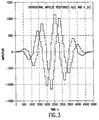
- envelope detection is achieved by implementing two FIR band-pass filters with approximately orthogonal impulse responses h(n) and h (n).
- the impulse responses h(n) and h (n) have equal (or almost equal) filter amplitude characteristics.
- a more detailed description of a preferred embodiment of the present invention starts with analog-to-digital conversion of an analog input signal, accomplished by means of a Sigma-Delta ( ⁇ - ⁇ ) modulator.
- Sigma Delta modulation is a well-known method of analog-to-digital conversion by the oversampling technique, described in greater detail in J.C. Candy and G.C. Temes, "Oversampling Delta-Sigma Converters," Oversampling Methods for A/D and D/A Conversion, eds. J.C. Candy and G.C. Temes, IEEE Press, 1991.
- the output of the ⁇ - ⁇ modulator is a binary sequence x(n) ⁇ [-1, +1] at a rate equal to the sampling rate f 0 .
- the spectrum X(f) of x(n) is composed of the spectrum of the audio input signal plus the shaped spectrum of the quantization noise.
- the convolutions of the input ⁇ - ⁇ input sequence x(n) with orthogonal FIR filter impulse responses h(n) and h (n), respectively, are performed in two stages: peripheral convolution and central convolution.
- the peripheral convolution involves low pass filtering and downsampling in a peripheral filter stage. Downsampling, or decimation, is the reduction in sampling rate by an integral factor.
- the low pass filter is operated at the comparatively high ⁇ - ⁇ rate f 0 , but the impulse response of the low pass filter is extremely simple. Thus, the implementation requires only few binary counters with variable increments.
- peripheral convolution results are stored in a peripheral RAM (Random Access Memory) at a rate (1/4s)f 0 , which corresponds to a decimation by a factor of 4s.
- Each peripheral convolution stage is implemented such that it operates completely independently of the following processing stages.
- the central convolution stage of a preferred embodiment involves convolution of the peripheral convolution results with two sets of comb filter weights. This is performed by means of an Arithmetic Logic Unit (ALU), which is driven by a micro program. Similar to a DSP, comparatively complicated operations, e.g. Multiply-and-Accumulate (MAC) operations, are performed. However, since the bandwidth of the envelope signals is comparatively low, the clock frequency of the ALU can be kept very low, resulting in strongly reduced ALU power consumption.
- ALU Arithmetic Logic Unit
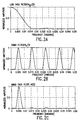
- the computational efficiency of the direct convolution technique of preferred embodiments is actually the result of choosing a low order filter design with a generally bell-shaped frequency response rather than a higher order filter with a more well-defined frequency response.
- a sixth order infinite impulse response Butterworth filter typically used in the prior art may have more sharply defined frequency responses, such a design requires significantly more system computations which in aggregate require relatively substantial power resources.
- some preliminary informal data suggest that users are not sensitive to the difference in frequency response. In fact, users actually seem to prefer the bell-shaped bandpass frequency response of preferred embodiments of the present invention over the more sharply defined frequency responses characteristic of the prior art.
- Each digital bandpass filter channel of a preferred embodiment is implemented by directly using the two-level high-frequency sequence x(n).
- the low pass filter h lp (n) represents the peripheral convolution stage and the comb filter ⁇ s (n) represents the central convolution stage described above.
- Response h 0 (n) is given by:
- Filter response ⁇ s (n) represents a comb filter composed of a set of weighted and equidistant unit impulses, The distance between the unit impulses is 8s.
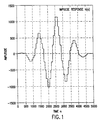
- Response h(n) represents a band pass filter with a resonance frequency which is approximately defined by the distance between the zero crossings. It aims at approximating an impulse response composed of four periods of a window-weighted sinusoid.
- coefficients w i are equal to the set w i , but with reversed order and different sign.
- h (n) can be obtained from h(n) by mirroring h(n) in time, inverting the sign, and introducing a time shift.
- H(f) I and I H (f) I are identical.
- the method used by preferred embodiments of the invention define orthogonal impulse responses h(n) and h (n) that allow an efficient implementation of downsampling stages and that is applicable for the integration in a digital low power ASIC (Application Specific Integrated Circuit).
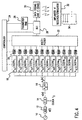
- FIG. 4 An example of an embodiment of a 12-channel filter bank in the context of a cochlear implant system is illustrated in FIG. 4.
- a microphone 10 worn behind the ear of a user transforms the acoustic signals in the user's environment into analog electrical signals.
- a preprocessor 12 performs additional preprocessing of the signal such as pre-emphasis or automatic gain control.
- the input audio signal is analog to digital converted by a ⁇ - ⁇ modulator 14 which uses the oversampling technique to produce a relatively high frequency digital sequence x(n) which is representative of the input audio signal at sampling frequency f 0 .
- the ⁇ - ⁇ sequence x(n) is then input to an input filter 16 where it is convolved with the input filter impulse response h 0 (n).
- this convolution requires only a few logic gates which convert the two level ⁇ - ⁇ sequence x(n) ⁇ [-1, +1] into a five-level sequence x 0 (n) ⁇ [0, ⁇ 1, ⁇ 2].
- the rate of x 0 (n) is equal to the ⁇ - ⁇ sampling frequency f 0 .
- Convolving x 0 (n) with h s,k (n) means to multiply and accumulate x 0 (n) and h s,k (n).
- peripheral filter 18 The convolution products at the peripheral filter counter outputs are then stored in turns in a 16-word peripheral convolution RAM 20 (also called a low pass RAM) where the sequence of RAM addresses is ... 0, 1, 2, ...14, 15, 0, 1, ... (ring configuration).
- peripheral convolution RAM 20 also called a low pass RAM
- the combination of peripheral filter 18 with peripheral convolution RAM 20 requires only parameter s k for correct operation, which is set during an initialization procedure by a controller unit 24 .
- the filter and WRITE operations of peripheral filters 18 and peripheral convolution RAMs 20 work completely autonomously, without being influenced by controller unit 24 or any other signal processing stage.
- the controller unit 24 in combination with a central convolution parameter RAM 26 (also called a comb filter weight RAM) also provides the instructions for an Arithmetic Logic Unit (ALU) 28 to perform the central convolutions with the comb filter weights and estimations of each bandpass envelope. If the controller unit 24 initiates the estimation of an envelope sample, the output of the peripheral convolution RAM 20 of the selected filter channel is connected to the ALU 28 via a multiplexer 22 , and the actual contents of that peripheral convolution RAM 20 are read into the ALU 28 .
- the ALU 28 produces a sequence of instantaneous bandpass envelopes for each filter channel.
- the ALU 28 of a preferred embodiment would also adjust the envelope amplitude by a loudness mapping function specific to the individual user' s hearing abilities.
- the loudness mapping may be an instantaneous logarithmic compression of the envelope and adjustment of the envelope amplitude above a threshold discerning level to a comfortable hearing level.
- the data coding and rf-stage 30 converts the sequence of instantaneous bandpass envelopes for each filter channel into a digital data stream which is radio transmitted.
- the implanted rf receiver/stimulator 32 worn by the user converts the received radio signal into narrow amplitude modulated biphasic stimulation pulses arranged sequentially by frequency band.
- Each frequency band has an associated electrode within the implanted portion of the device such that the electrode for a given frequency band will stimulate the neural fibers for that band of frequencies with the cochlea of the ear.
- the pulsatile stimulation of the cochlear neural fibers by the electrodes 34 induce stochastically distributed action potentials in the neural fibers which resemble the physiological response patterns of the stochastic activations of neural fibers in a healthy ear.
- the envelope signals e k (n ⁇ ) in FIG. 4 are calculated sequentially, controlled by a micro program.
- the peripheral convolution involves low pass filtering and downsampling in peripheral filter stages. These peripheral filters are operated at the comparatively high ⁇ - ⁇ -rate f 0 , but the impulse responses are extremely simple.
- the implementation requires only two counters with variable increments. Thus, the power consumption can be kept extremely low, if asynchronous counters are used. If an asynchronous counter of arbitrary length is driven at clock frequency f 0 , then on average only two flip flops toggle and hence contribute to the power consumption.
- This step requires more complex hardware, including an ALU which contains registers, a multiplier, etc., however, the clock frequency of the ALU can be kept very low.
- the clock frequency of the ALU can be kept very low.
- the power consumption of peripheral plus central convolution is approximately 2.68 mW, which is less than 1% of the 300 mW power consumption typical in a commercial DSP implementation of the CIS strategy.
Landscapes
- Physics & Mathematics (AREA)
- Engineering & Computer Science (AREA)
- Computer Hardware Design (AREA)
- Mathematical Physics (AREA)
- Compression, Expansion, Code Conversion, And Decoders (AREA)
- Filters That Use Time-Delay Elements (AREA)
- Analogue/Digital Conversion (AREA)
- Networks Using Active Elements (AREA)
Claims (35)
- Digitales Bandpass-Filter mit endlichem Impuls-Ansprechverhalten zur Verarbeitung eines Eingangssignals, wobei das Filter aufweist:einen Analog/Digital-Konverter vom Überabtastungstyp zum Konvertieren des Eingangssignals in eine Digital-Sequenz;ein TP-FIR (mit endlichem Impuls-Ansprechverhalten) -filter zum Falten der Digital-Sequenz zur Erzeugung eines TP-Vektors;ein digitales Kamm-Filter, welches durch wenigstens einen Satz von Kamm-Filter-Gewichtungen definiert wird, die repräsentativ sind für die gewichteten und zeitverschobenen Einheitsimpulse, um den Tiefpass-Vektor mit den Kamm-Filter-Gewichtungen zu falten bzw. zusammenzurollen; undeinen Hüllkurven-Detektor zum Erfassen einer Bandpass-Hüllkurve des digitalen FIR-Bandpass-Filters.
- Digitales FIR-Bandpass-Filter nach Anspruch 1, bei dem der Analog-Digital-Konverter Sigma-Delta-Modulation anwendet.
- Digitales FIR-Bandpass-Filter nach Anspruch 1, bei dem die digitale Sequenz eine Zwei-Stufen-Binär-Sequenz ist.
- Digitales FIR-Bandpass-Filter nach Anspruch 1, bei dem das Tiefpass-FIR-Filter die digitale Sequenz direkt durch Multiplizieren und Kumulieren der digitalen Sequenz mit einem Tiefpass-FIR-Filter-Impuls-Ansprechverhalten faltet.
- Digitales FIR-Bandpass-Filter nach Anspruch 1, bei dem das Tiefpass-FIR-Filter besteht aus:einem Eingangsfilter, um die Digital-Sequenz zu falten, um eine mehrstufige Sequenz zu erzeugen, die eine Vielzahl von zulässigen Werten aufweist;einem peripheren Filter zum Falten der mehrstufigen Sequenz zur Erzeugung eines Tiefpass-Vektors;einer Ausgangsstufe, die wenigstens einen Ausgangszähler zum Abwärts-Abtasten des Tiefpass-Vektors zu ausgewählten Zeiten beinhaltet; undeinem Tiefpass-RIM-Speicher zum sequenziellen Speichern des abwärts abgetasteten Tiefpass-Vektors.
- Ein digitales FIR-Bandpass-Filter nach Anspruch 5, bei dem die mehrstufige Sequenz eine fünfstufige Sequenz ist.
- Digitales FIR-Bandpass-Filter nach Anspruch 5, bei dem das digitale Kamm-Filter aufweist:ein Kamm-Filter-Gewichtungs-RAM zur Speicherung der Sätze der Kamm-Filter-Gewichtungen; undeine arithmetische logische Einheit ALU zur Berechnung eines Faltungsproduktes des abwärts abgetasteten Tiefpass-Vektors mit den Kamm-Filter-Gewichtungen.
- Digitales FIR-Bandpass-Filter nach Anspruch 7, bei dem das Kamm-Filter-Gewichtungs-RAM zwei orthogonale Sätze von Kamm-Filter-Gewichtungen speichert und die ALU die Faltungsprodukte des abwärts getasteten Tiefpass-Vektors mit zwei orthogonalen Sätzen von Kamm-Filter-Gewichtungen speichert.
- Digitales FIR-Bandpass-Filter nach Anspruch 8, bei dem die ALU einen Detektor für die Hüllkurve aufweist.
- Digitales FIR-Bandpass-Filter nach Anspruch 9, bei dem die ALU bei einer Frequenz arbeitet, die weniger als das Zweifache einer maximalen Bandpass-Frequenz des digitalen FIR-Bandpass-Filters aufweist.
- Digitales FIR-Bandpass-Filter nach Anspruch 9, bei dem die ALU die Bandpass-Hüllkurve des digitalen FIR-Bandpass-Filters dadurch abschätzt, dass die Wurzel aus einer Summe der Quadrate der Faltungsprodukte berechnet wird, welche durch die ALU berechnet wurden.
- Digitales FIR-Bandpass-Filter nach Anspruch 11, bei dem die ALU die Werte der Wurzel bzw. Quadratwurzel der Summe aus zwei Quadraten ermittelt durch:Bestimmung der größeren Wurzel der zwei Quadrate und der kleineren der Wurzel der zwei Quadrate;Berechnen einer Summe einer Hälfte der kleineren der Wurzeln der beiden Quadrate und einer Hälfte eines Produktes der größeren der Wurzeln der beiden Quadrate und der Quadratwurzel von drei; undAuswählen, welche von den größeren der Wurzeln der zwei Quadrate und der berechneten Summe größer ist.
- Digitales FIR-Bandpass-Filter nach Anspruch 1, bei dem der Hüllkurven-Detektor eine Bandpass-Hüllkurve des digitalen FIR-Bandpass-Filters durch Berechnung einer Quadratwurzel einer Summe von Quadraten der Faltungsprodukte berechnet, die durch das digitale Kamm-Filter berechnet sind.
- Digitales FIR-Bandpass-Filter nach Anspruch 13, bei dem der Hüllkurven-Detektor den Wert der Quadratwurzel der Summe der beiden Quadrate ermittelt durch:Bestimmung der größeren der Wurzeln der beiden Quadrate und der kleineren der Wurzeln der beiden Quadrate;Berechnen einer Summe einer Hälfte der kleineren der Wurzeln der beiden Quadrate und einer Hälfte eines Produktes der größeren der Wurzeln der zwei Quadrate und der Quadratwurzel von 3; undAuswählen, welche größer ist aus der größeren der Wurzeln der zwei Quadrate und der berechneten Summe.
- Kochleares Implantat-System mit:einem implantierbaren Abschnitt zur Implantation in einer Person zur Erzeugung auditorischer Signale für den Patienten; undeinen externen Abschnitt zur Erzeugung der auditorischen Signale zum implantierbaren Abschnitt, wobei der externe Abschnitt das digitale FIR-Bandpass-Filter nach Anspruch 1 beinhaltet.
- Verfahren zur Verarbeitung eines Eingangssignales durch ein digitales Bandpass-Filter mit endlichem Impuls-Ansprechverhalten (FIR), wobei das Verfahren aufweist:Konvertieren des Eingangssignales in eine digitale Sequenz in einem Analog-Digital-Konverter durch Überabtasten (Oversampling);Falten der Digital-Sequenz in einem Tiefpass-FIR-Filter zur Erzeugung eines Tiefpass-Vektors;Falten des Tiefpass-Vektors in einem digitialen Kamm-Filter, welches durch wenigstens einen Satz von Kamm-Filter-Gewichtungen definiert ist, die für die gewichteten und zeitverschobenen Einheitsimpulse repräsentativ sind; undErfassen einer Bandpass-Hüllkurve des digitalen FIR-Bandpass-Filters in einem Hüllkurven-Detektor.
- Verfahren zur Verarbeitung eines Eingangssignals durch ein digitales Bandpass-Filter mit endlichem Impuls-Ansprechverhalten, FIR, wobei das Verfahren aufweist:Konvertieren des Eingangssignals in eine Digitalsequenz durch Oversampling in einem Analog-Digital-Konverter;Falten der Digital-Sequenz in einem Eingangsfilter zur Erzeugung einer mehrstufigen Sequenz, welche eine Vielzahl von zulässigen Werten beinhaltet;direktes Falten der Mehrstufen-Sequenz in einem peripheren Filter zur Erzeugung eines Tiefpass-Vektors;Abwärts-Abtasten des Tiefpass-Vektors zu ausgewählten Zeiten mit einer Ausgangsstufe, welche wenigstens einen Ausgangszähler beinhaltet;sequenzielle Speicherung des abwärts abgetasteten Tiefpass-Vektors in einem Tiefpass-RAM-Speicher;Berechnen des Faltungsproduktes des abwärts abgetasteten Tiefpass-Vektors mit zwei orthogonalen Sätzen von Kamm-Filter-Gewichtungen, die repräsentativ sind für die gewichteten und zeitverschobenen Einheitsimpulse eines digitalen Kamm-Filters in einer arithmetischen logischen Einheit ALU; Abschätzen einer Bandpass-Hüllkurve des digitalen FIR-Bandpass-Filters durch Berechnen einer Quadratwurzel aus der Summe von Quadraten der Faltungsprodukte, die in der ALU berechnet wurden, in der ALU, wobei der Wert der Quadratwurzel der Summe der beiden Quadrate abgeschätzt wird durch:Bestimmen der größeren der Wurzeln der beiden Quadrate und der kleineren der Wurzeln der beiden Quadrate;Berechnen einer Summe von einer Hälfte der kleineren der Wurzeln der beiden Quadrate und einer Hälfte eines Produktes der größeren der Wurzeln der beiden Quadrate und der Quadratwurzel von drei; undAuswählen, was größer ist von der größeren der Wurzeln der beiden Quadrate und der berechneten Summe.
- Digitale Filterbank zur Verarbeitung eines Eingangssignals, welche aus einer Vielzahl von digitalen Bandpass-Filtern bzw. FIR-Filtern mit endlichem Impuls-Ansprechverhalten besteht, die parallel zueinander angeordnet sind, wobei die Filterbank aufweist:einen Analog/Digital-Konverter vom Oversampling-Typ zum Konvertieren des Eingangssignals in eine Digitalsequenz;eine Vielzahl von Tiefpass-FIR-Filtern, die parallel zueinander angeordnet sind, um die Digital-Sequenz zu falten zur Erzeugung einer Vielzahl von Tiefpass-Vektoren;eine Vielzahl von digitalen Kamm-Filtern, die jeweils einem der Vielzahl von Tiefpass-FIR-Filtern zugeordnet sind und jeweils durch wenigstens einen Satz von Kamm-Filter-Gewichtungen definiert sind, welche für die gewichteten und zeitverschobenen Einheitsimpulse repräsentativ sind, bei welchen jedes der Vielzahl von digitalen Kamm-Filtern den Tiefpass-Vektor des zugeordneten Tiefpass-FIR-Filters faltet mit den Kamm-Filter-Gewichtungen; undeinen Detektor für die Hüllkurve zur sequenziellen Erfassung einer Bandpass-Hüllkurve jedes der Vielzahl von digitalen FIR-Bandpass-Filtern.
- Digitale Filterbank nach Anspruch 18, bei der der Analog/Digital-Konverter die Sigma-Delta-Modulation verwendet.
- Digitale Filterbank nach Anspruch 18, bei welcher die Digital-Sequenz eine zweistufige Binärsequenz ist.
- Digitale Filterbank nach Anspruch 18, bei welcher jedes der Vielzahl von Tiefpass-FIR-Filtern die Digital-Sequenz direkt durch Multiplizieren und Akkumulieren der Digital-Sequenz mit einer Tiefpass-Filter-Impuls-Antwort faltet.
- Digitale Filterbank nach Anspruch 18, bei der jedes der Vielzahl von FIR-Bandpass-Filtern die gewichteten und zeitverschobenen Einheitsimpulse des zugeordneten Kamm-Filters durch einen Skalierungsfaktor mulitpliziert, der invers proportional zur Mitten-Bandpass-Frequenz des FIR-Bandpass-Filters ist, um in gleicher Weise die Bandpass-Frequenzen der FIR-Bandpass-Filter zu verstärken.
- Digitale Filterbank nach Anspruch 18, bei welcher die Vielzahl der Tiefpass-FIR-Filter weiter aufweist:ein Eingangsfilter, welches die Digital-Sequenz faltet, um eine mehrstufige Sequenz mit einer Vielzahl von zulässigen Werten zu erzeugen;eine Vielzahl von peripheren Filtern, die parallel angeordnet sind, welche die mehrstufige Sequenz faltet, um die Vielzahl der Tiefpass-Vektoren zu erzeugen, undbei welchen jedes periphere Filter aufweist:eine Ausgangsstufe mit wenigstens einem Ausgang bzw. Ausgangssignalzähler, der den Tiefpass-Vektor zu ausgewählten Zeiten abwärts abtastet, undeinen Tiefpass-RAM-Speicher, der sequenziell den abwärts abgetasteten Tiefpass-Vektor speichert.
- Digitale Filterbank nach Anspruch 23, bei welcher die mehrstufige Sequenz eine fünfstufige Sequenz ist.
- Digitale Filterbank nach Anspruch 23, bei welcher die Vielzahl der digitalen Kamm-Filter weiterhin aufweist:einen Kamm-Filter-Gewichtungs-RAM zur Speicherung der Sätze von Kamm-Filter-Gewichtungen für jedes der Vielzahl von digitalen Kamm-Filtern; undeine arithmetische logische Einheit ALU zur sequenziellen Berechnung eines Faltungsproduktes jedes der Vielzahl von abwärts abgetasteten Tiefpass-Vektoren mit den Kamm-Filter-Gewichtungen des zugeordneten digitalen Kamm-Filters.
- Digitiale Filterbank nach Anspruch 25, bei der das Kamm-Filter-Gewichtungs-RAM zwei orthogonale Sätze von Kamm-Filter-Gewichtungen für jedes der Vielzahl von digitalen Kamm-Filtern speichert und die ALU sequenziell die Faltungsprodukte aus jedem der Vielzahl von abwärts abgetasteten Tiefpass-Vektoren mit den zwei orthogonalen Sätzen der Kamm-Filter-Gewichtungen des zugeordneten digitalen Kamm-Filters berechnet.
- Digitale Filterbank nach Anspruch 26, bei welcher die ALU weiterhin aufweist einen Hüllkurven-Detektor.
- Digitale Filterbank nach Anspruch 27, bei welcher die ALU bei einer Frequenz arbeitet, die kleiner ist als das Zweifache einer maximalen Bandpass-Frequenz der digitalen Filterbank.
- Digitale Filterbank nach Anspruch 27, bei welcher die ALU die Bandpass-Hüllkurve jedes der Vielzahl von FIR-Bandpass-Filter abschätzt durch:Berechnen einer Quadratwurzel aus der Summe der Quadrate der Faltungsprodukte der abwärts abgetasteten Tiefpass-Vektoren mit den zwei orthogonalen Sätzen der Kamm-Filter-Gewichtungen des zugeordneten digitalen Kamm-Filters.
- Digitale Filterbank nach Anspruch 29, bei welcher die ALU den Wert der Quadratwurzel der Summe von zwei Quadraten abschätzt durch:Festlegen der größeren der Wurzeln der beiden Quadrate und der kleineren der Wurzeln der beiden Quadrate;Berechnen einer Summe aus einer Hälfte der kleineren Wurzeln der beiden Quadrate und einer Hälfte eines Produktes der größeren Wurzel der beiden Quadrate und der Quadratwurzel von drei; undAuswählen, was größer ist von der größeren der Wurzeln der beiden Quadrate und der berechneten Summe.
- Digitale Filterbank nach Anspruch 18, bei welcher der Hüllkurven-Detektor sequenziell eine Bandpass-Hüllkurve jedes der Vielzahl von FIR-Bandpass-Filtern erfasst, indem für jedes der Vielzahl von digitalen Kamm-Filtern eine Quadratwurzel der Summe der Quadrate der Faltungsprodukte berechnet wird, welche durch das digitale Kamm-Filter berechnet wird.
- Digitales FIR-Bandpass-Filter nach Anspruch 31, bei dem der Hüllkurven-Detektor den Wert der Quadratwurzel aus der Summe der zwei Quadrate berechnet durch:Bestimmen der größeren der Wurzeln der beiden Quadrate und der kleineren der Wurzeln der beiden Quadrate;Berechnen einer Summe einer Hälfte der niedrigeren der Wurzeln der beiden Quadrate und einer Hälfte eines Produktes der größeren der Wurzeln der beiden Quadrate und der Quadratwurzel aus drei; undAuswählen, was größer ist zwischen der größeren der Wurzeln der beiden Quadrate und der berechneten Summe.
- Kochleares Implantationssystem mit:einem implantierbaren Abschnitt zur Implantation in einer Person zur Erzeugung auditorischer Signale zu dem Patienten; undeinem externen Abschnitt zur Lieferung von auditorischen Signalen an den implantierbaren Abschnitt, wobei der externe Abschnitt die digitale Filterbank nach Anspruch 18 beinhaltet.
- Verfahren zur Verarbeitung eines Eingangssignals durch eine digitale Filterbank, die eine Vielzahl von digitalen Bandpass-Filtern mit endlichem Impuls-Ansprechverhalten bzw. Signal FIR aufweist die parallel angeordnet sind, wobei das Verfahren beinhaltet:Konvertieren des Eingangssignals in eine Digitalsequenz in einem Analog/Digital-Konverter durch Oversampling;Falten der Digital-Sequenz in jedem der Vielzahl von Tiefpass-FIR-Filtern, die parallel angeordnet sind, um eine Vielzahl von Tiefpass-Vektoren zu liefern;sequenzielles Falten jedes der Vielzahl von Tiefpass-Vektoren in einer Vielzahl von digitalen Kamm-Filtern, die jeweils einem der Vielzahl von Tiefpass-FIR-Filtern zugeordnet sind und jeweils durch wenigstens einen Satz von Kamm-Filter-Gewichtungen definiert sind, welche repräsentativ sind für die gewichteten und zeitverschobenen Einheitsimpulse; undsequenzielles Erfassen einer Bandpass-Hüllkurve jedes der Vielzahl von digitalen FIR-Bandpass-Filtern in einem Hüllkurven-Detektor.
- Verfahren zur Verarbeitung eines Eingangssignales durch eine digitale Filterbank, die aus einer Vielzahl von digitalen Bandpass-Filtern mit endlichem Impuls-Ansprechverhalten bzw. Signal, FIR, die parallel angeordnet sind, wobei das Verfahren beinhaltet:Konvertieren des Eingangssignals in eine Digitalsequenz in einem Analog/Digital-Konverter durch Oversampling;Falten der Digital-Sequenz in einem Eingangsfilter zur Erzeugung einer mehrstufigen Sequenz mit einer Vielzahl von zusätzlichen Werten;direktes Falten der mehrstufigen Sequenz in jedem von einer Vielzahl von peripheren Filtern, die parallel angeordnet sind, um eine Vielzahl von Tiefpass-Vektoren zu erzeugen;Abtasten in Abwärtsrichtung der Vielzahl von Tiefpass-Vektoren zu ausgewählten Zeiten mit einer zugeordneten Ausgangsstufe, welche wenigstens einen Ausgangszähler beinhaltet;sequenzielles Speichern der Vielzahl von in Abwärtsrichtung abgetasteten Tiefpass-Vektoren in einer Vielzahl von zugeordneten Tiefpass-RAM-Speichern RAM;sequenzielles Berechnen der Faltungsprodukte jedes der Vielzahl von abwärts abgetasteten Tiefpass-Vektoren mit zwei orthogonalen Sätzen von Kamm-Filter-Gewichtungen, die repräsentativ sind für die gewichteten und zeitverschobenen Einheitsimpulse eines zugeordneten digitalen Kamm-Filters, in einer arithmetisch logischen Einheit ALU;sequenzielles Abschätzen einer Bandpass-Hüllkurve jedes der Vielzahl von FIR-Bandpass-Filter durch Berechnen einer Quadratwurzel aus der Summe von Quadraten der Faltungsprodukte jedes der Vielzahl von abwärts abgetasteten Tiefpass-Vektoren mit den zwei orthogonalen Sätzen der Kamm-Filter-Gewichtungen der zugehörigen digitalen Kamm-Filter in der ALU, wobei der Wert der Quadratwurzel der Summe der zwei Quadrate abgeschätzt wird durch:Bestimmen der größeren der Wurzeln der beiden Quadrate und der kleineren der Wurzeln der beiden Quadrate;Berechnen einer Summe von einer Hälfte der kleineren der Wurzeln der beiden Quadrate und einer Hälfte eines Produktes der größeren der Wurzeln der beiden Quadrate und der Quadratwurzel aus drei; undAuswählen, was größer ist von der größeren der Wurzeln der beiden Quadrate und der berechneten Summe.
Applications Claiming Priority (3)
| Application Number | Priority Date | Filing Date | Title |
|---|---|---|---|
| US4527997P | 1997-05-01 | 1997-05-01 | |
| US45279P | 1997-05-01 | ||
| PCT/US1998/008520 WO1998049775A1 (en) | 1997-05-01 | 1998-04-28 | Apparatus and method for a low power digital filter bank |
Publications (2)
| Publication Number | Publication Date |
|---|---|
| EP0979554A1 EP0979554A1 (de) | 2000-02-16 |
| EP0979554B1 true EP0979554B1 (de) | 2003-08-27 |
Family
ID=21936983
Family Applications (1)
| Application Number | Title | Priority Date | Filing Date |
|---|---|---|---|
| EP98918820A Expired - Lifetime EP0979554B1 (de) | 1997-05-01 | 1998-04-28 | Verfahren und gerät für eine digitale filterbank mit geringem stromverbrauch |
Country Status (8)
| Country | Link |
|---|---|
| US (2) | US5983139A (de) |
| EP (1) | EP0979554B1 (de) |
| JP (1) | JP4293639B2 (de) |
| AT (1) | ATE248459T1 (de) |
| AU (1) | AU750976B2 (de) |
| CA (1) | CA2287261C (de) |
| DE (1) | DE69817555T2 (de) |
| WO (1) | WO1998049775A1 (de) |
Families Citing this family (65)
| Publication number | Priority date | Publication date | Assignee | Title |
|---|---|---|---|---|
| US6219580B1 (en) * | 1995-04-26 | 2001-04-17 | Advanced Bionics Corporation | Multichannel cochlear prosthesis with flexible control of stimulus waveforms |
| JP3545926B2 (ja) * | 1997-12-03 | 2004-07-21 | シャープ株式会社 | 原稿読み取り装置 |
| CA2318407C (en) * | 1998-01-12 | 2008-07-29 | Imperial College Of Science, Technology & Medicine | Audio signal processors |
| AUPP790598A0 (en) | 1998-12-23 | 1999-01-28 | Lake Dsp Pty Limited | Efficient impulse response convolution method and apparatus |
| US7917224B2 (en) | 1999-07-21 | 2011-03-29 | Med-El Elektromedizinische Geraete Gmbh | Simultaneous stimulation for low power consumption |
| JP4819268B2 (ja) | 1999-08-26 | 2011-11-24 | メド−エル・エレクトロメディツィニシェ・ゲラーテ・ゲーエムベーハー | チャネル特定サンプリングシーケンスに基づく電気的神経刺激 |
| US8165686B2 (en) | 1999-08-26 | 2012-04-24 | Med-El Elektromedizinische Geraete Gmbh | Simultaneous intracochlear stimulation |
| EP1216014B1 (de) * | 1999-09-16 | 2005-04-20 | Advanced Bionics N.V. | Cochlea-implantat |
| IL133451A0 (en) * | 1999-12-10 | 2001-04-30 | Dspc Tech Ltd | Programmable convolver |
| US7076315B1 (en) * | 2000-03-24 | 2006-07-11 | Audience, Inc. | Efficient computation of log-frequency-scale digital filter cascade |
| US6728578B1 (en) * | 2000-06-01 | 2004-04-27 | Advanced Bionics Corporation | Envelope-based amplitude mapping for cochlear implant stimulus |
| ATE394755T1 (de) * | 2000-06-20 | 2008-05-15 | Nxp Bv | Datenverarbeitungsgerät |
| ATE303671T1 (de) * | 2000-07-11 | 2005-09-15 | Koninkl Philips Electronics Nv | Schaltung zur automatischen verstärkungsregelung |
| US7062523B1 (en) * | 2000-08-01 | 2006-06-13 | Analog Devices, Inc. | Method for efficiently computing a fast fourier transform |
| CN100574158C (zh) * | 2001-08-27 | 2009-12-23 | 加利福尼亚大学董事会 | 用于改善音频信号的方法与装置 |
| AU2002363103B2 (en) * | 2001-10-24 | 2008-10-16 | Med-El Elektromedizinische Gerate Ges.M.B.H. | Implantable fluid delivery apparatuses and implantable electrode |
| US20070088335A1 (en) * | 2001-10-24 | 2007-04-19 | Med-El Elektromedizinische Geraete Gmbh | Implantable neuro-stimulation electrode with fluid reservoir |
| US7013319B1 (en) | 2001-11-20 | 2006-03-14 | Analog Devices, Inc. | Digital filter methods and structures for increased processing rates |
| US7130694B1 (en) * | 2001-12-26 | 2006-10-31 | Advanced Bionics Corporation | Pulse skipping strategy |
| US7338028B2 (en) * | 2002-12-02 | 2008-03-04 | Med-El Elektromedizinische Geraete Gmbh | Fluid switch controlled trans-cutaneously via magnetic force |
| AU2003901634A0 (en) * | 2003-04-04 | 2003-05-01 | Cochlear Limited | Reduced power consumption in audio processors |
| US20050047537A1 (en) * | 2003-08-29 | 2005-03-03 | Ting-Yuan Cheng | Method and system of signal path tracking |
| WO2005072608A1 (en) * | 2004-01-29 | 2005-08-11 | Everest Biomedical Instruments Co. | Method and apparatus for wireless brain interface |
| US20060083343A1 (en) * | 2004-10-19 | 2006-04-20 | Kawasaki Microelectronics, Inc. | Clock generation using phase interpolators |
| US20060212094A1 (en) * | 2004-12-31 | 2006-09-21 | Ludwig Moser | Middle ear multi-channel electrode |
| US7515966B1 (en) * | 2005-03-14 | 2009-04-07 | Advanced Bionics, Llc | Sound processing and stimulation systems and methods for use with cochlear implant devices |
| US7996212B2 (en) * | 2005-06-29 | 2011-08-09 | Fraunhofer-Gesellschaft Zur Foerderung Der Angewandten Forschung E.V. | Device, method and computer program for analyzing an audio signal |
| US8345890B2 (en) | 2006-01-05 | 2013-01-01 | Audience, Inc. | System and method for utilizing inter-microphone level differences for speech enhancement |
| US8204252B1 (en) | 2006-10-10 | 2012-06-19 | Audience, Inc. | System and method for providing close microphone adaptive array processing |
| US8744844B2 (en) * | 2007-07-06 | 2014-06-03 | Audience, Inc. | System and method for adaptive intelligent noise suppression |
| US8194880B2 (en) | 2006-01-30 | 2012-06-05 | Audience, Inc. | System and method for utilizing omni-directional microphones for speech enhancement |
| US9185487B2 (en) * | 2006-01-30 | 2015-11-10 | Audience, Inc. | System and method for providing noise suppression utilizing null processing noise subtraction |
| AR059786A1 (es) * | 2006-03-09 | 2008-04-30 | Med El Elektromed Geraete Gmbh | Configuracion de electrodo de implante coclear para eluir farmacos |
| US8046081B2 (en) * | 2006-05-18 | 2011-10-25 | Med-El Elektromedizinische Geraete Gmbh | Implanted system with DC free inputs and outputs |
| US8949120B1 (en) | 2006-05-25 | 2015-02-03 | Audience, Inc. | Adaptive noise cancelation |
| US8150065B2 (en) * | 2006-05-25 | 2012-04-03 | Audience, Inc. | System and method for processing an audio signal |
| US8849231B1 (en) | 2007-08-08 | 2014-09-30 | Audience, Inc. | System and method for adaptive power control |
| US8204253B1 (en) | 2008-06-30 | 2012-06-19 | Audience, Inc. | Self calibration of audio device |
| US8934641B2 (en) | 2006-05-25 | 2015-01-13 | Audience, Inc. | Systems and methods for reconstructing decomposed audio signals |
| US8259926B1 (en) | 2007-02-23 | 2012-09-04 | Audience, Inc. | System and method for 2-channel and 3-channel acoustic echo cancellation |
| US8391993B2 (en) * | 2007-07-13 | 2013-03-05 | Cochlear Limited | Using interaction to measure neural excitation |
| US8189766B1 (en) | 2007-07-26 | 2012-05-29 | Audience, Inc. | System and method for blind subband acoustic echo cancellation postfiltering |
| US8143620B1 (en) | 2007-12-21 | 2012-03-27 | Audience, Inc. | System and method for adaptive classification of audio sources |
| US8180064B1 (en) | 2007-12-21 | 2012-05-15 | Audience, Inc. | System and method for providing voice equalization |
| US8194882B2 (en) | 2008-02-29 | 2012-06-05 | Audience, Inc. | System and method for providing single microphone noise suppression fallback |
| US8355511B2 (en) | 2008-03-18 | 2013-01-15 | Audience, Inc. | System and method for envelope-based acoustic echo cancellation |
| US8774423B1 (en) | 2008-06-30 | 2014-07-08 | Audience, Inc. | System and method for controlling adaptivity of signal modification using a phantom coefficient |
| US8521530B1 (en) | 2008-06-30 | 2013-08-27 | Audience, Inc. | System and method for enhancing a monaural audio signal |
| CA2740877C (en) * | 2008-10-15 | 2015-02-03 | Med-El Elektromedizinische Geraete Gmbh | Inner ear drug delivery device and method |
| AU2009313316B2 (en) * | 2008-11-10 | 2013-07-18 | Med-El Elektromedizinische Geraete Gmbh | Hydrogel-filled drug delivery reservoirs |
| SG174887A1 (en) * | 2009-04-30 | 2011-11-28 | Widex As | Input converter for a hearing aid and signal conversion method |
| US20110257704A1 (en) * | 2009-10-23 | 2011-10-20 | Med-El Elektromedizinische Geraete Gmbh | Equal Loudness Contour with Channel Specific Map Laws |
| WO2011050237A1 (en) * | 2009-10-23 | 2011-04-28 | Med-El Elektromedizinische Geraete Gmbh | Channel-specific loudness mapping for prosthetic hearing systems |
| US9008329B1 (en) | 2010-01-26 | 2015-04-14 | Audience, Inc. | Noise reduction using multi-feature cluster tracker |
| JP5351304B2 (ja) * | 2012-04-19 | 2013-11-27 | ファナック株式会社 | Δς変調型ad変換器を有するモータ制御装置 |
| ITTO20120530A1 (it) * | 2012-06-19 | 2013-12-20 | Inst Rundfunktechnik Gmbh | Dynamikkompressor |
| US20130345775A1 (en) * | 2012-06-21 | 2013-12-26 | Cochlear Limited | Determining Control Settings for a Hearing Prosthesis |
| US9640194B1 (en) | 2012-10-04 | 2017-05-02 | Knowles Electronics, Llc | Noise suppression for speech processing based on machine-learning mask estimation |
| US9536540B2 (en) | 2013-07-19 | 2017-01-03 | Knowles Electronics, Llc | Speech signal separation and synthesis based on auditory scene analysis and speech modeling |
| CN106797512B (zh) | 2014-08-28 | 2019-10-25 | 美商楼氏电子有限公司 | 多源噪声抑制的方法、系统和非瞬时计算机可读存储介质 |
| WO2017027542A1 (en) * | 2015-08-11 | 2017-02-16 | Med-El Elektromedizinische Geraete Gmbh | Multichannel opto-mechanical stimulation |
| JP6446145B2 (ja) | 2015-09-28 | 2018-12-26 | 旭化成エレクトロニクス株式会社 | ハウリング抑制装置 |
| DE102022111300A1 (de) * | 2022-05-06 | 2023-11-09 | Elevear GmbH | Vorrichtung zur Reduzierung des Rauschens bei der Wiedergabe eines Audiosignals mit einem Kopfhörer oder Hörgerät und entsprechendes Verfahren |
| US12034619B2 (en) * | 2022-07-11 | 2024-07-09 | Viavi Solutions Inc. | Upstream signal leakage detection in high-split cable network |
| WO2025216112A1 (ja) * | 2024-04-12 | 2025-10-16 | パナソニックIpマネジメント株式会社 | 信号処理方法、信号処理装置、およびプログラム |
Family Cites Families (10)
| Publication number | Priority date | Publication date | Assignee | Title |
|---|---|---|---|---|
| US5027306A (en) * | 1989-05-12 | 1991-06-25 | Dattorro Jon C | Decimation filter as for a sigma-delta analog-to-digital converter |
| US5012245A (en) * | 1989-10-04 | 1991-04-30 | At&T Bell Laboratories | Integral switched capacitor FIR filter/digital-to-analog converter for sigma-delta encoded digital audio |
| US5227991A (en) * | 1991-11-20 | 1993-07-13 | Motorola, Inc. | Comb filter including a data overflow monitor, and a radio including the same |
| US5323157A (en) * | 1993-01-15 | 1994-06-21 | Motorola, Inc. | Sigma-delta digital-to-analog converter with reduced noise |
| US5357252A (en) * | 1993-03-22 | 1994-10-18 | Motorola, Inc. | Sigma-delta modulator with improved tone rejection and method therefor |
| US5408235A (en) * | 1994-03-07 | 1995-04-18 | Intel Corporation | Second order Sigma-Delta based analog to digital converter having superior analog components and having a programmable comb filter coupled to the digital signal processor |
| US5549658A (en) * | 1994-10-24 | 1996-08-27 | Advanced Bionics Corporation | Four-Channel cochlear system with a passive, non-hermetically sealed implant |
| US5601617A (en) * | 1995-04-26 | 1997-02-11 | Advanced Bionics Corporation | Multichannel cochlear prosthesis with flexible control of stimulus waveforms |
| US5626629A (en) * | 1995-05-31 | 1997-05-06 | Advanced Bionics Corporation | Programming of a speech processor for an implantable cochlear stimulator |
| US5731769A (en) * | 1995-12-04 | 1998-03-24 | Motorola, Inc. | Multi-rate digital filter apparatus and method for sigma-delta conversion processes |
-
1998
- 1998-04-28 EP EP98918820A patent/EP0979554B1/de not_active Expired - Lifetime
- 1998-04-28 US US09/067,673 patent/US5983139A/en not_active Expired - Lifetime
- 1998-04-28 AU AU71673/98A patent/AU750976B2/en not_active Expired
- 1998-04-28 DE DE69817555T patent/DE69817555T2/de not_active Expired - Lifetime
- 1998-04-28 AT AT98918820T patent/ATE248459T1/de active
- 1998-04-28 WO PCT/US1998/008520 patent/WO1998049775A1/en not_active Ceased
- 1998-04-28 JP JP54728498A patent/JP4293639B2/ja not_active Expired - Fee Related
- 1998-04-28 CA CA002287261A patent/CA2287261C/en not_active Expired - Fee Related
-
1999
- 1999-07-26 US US09/360,547 patent/US6182103B1/en not_active Expired - Lifetime
Also Published As
| Publication number | Publication date |
|---|---|
| DE69817555T2 (de) | 2004-06-17 |
| AU750976B2 (en) | 2002-08-01 |
| CA2287261C (en) | 2007-10-23 |
| WO1998049775A1 (en) | 1998-11-05 |
| US6182103B1 (en) | 2001-01-30 |
| AU7167398A (en) | 1998-11-24 |
| EP0979554A1 (de) | 2000-02-16 |
| ATE248459T1 (de) | 2003-09-15 |
| JP4293639B2 (ja) | 2009-07-08 |
| US5983139A (en) | 1999-11-09 |
| JP2002511986A (ja) | 2002-04-16 |
| DE69817555D1 (de) | 2003-10-02 |
| CA2287261A1 (en) | 1998-11-05 |
Similar Documents
| Publication | Publication Date | Title |
|---|---|---|
| EP0979554B1 (de) | Verfahren und gerät für eine digitale filterbank mit geringem stromverbrauch | |
| EP0986933B1 (de) | Frequenz-kontinuierlich dynamikbereichsaudiokompression | |
| Lyon | A computational model of filtering, detection, and compression in the cochlea | |
| US8137269B2 (en) | Method and system for managing physiological system | |
| CN1640190B (zh) | 使用数字频率扭曲的动态范围压缩 | |
| WO2000041621A1 (en) | Electrocardiograph having large low frequency dynamic range | |
| Irino et al. | An analysis/synthesis auditory filterbank based on an IIR implementation of the gammachirp | |
| WO2016086849A1 (zh) | 用于数字助听器的低复杂度可调滤波器组及其工作方法 | |
| EP1305975B1 (de) | Adaptives mikrofon-array-system mit erhaltung binauraler hinweise | |
| Haridas et al. | Efficient Farrow structure based bank of variable bandwidth filters for digital hearing aids | |
| CN110772713B (zh) | 具有改进的用于确定时间精细结构参数的方法的耳蜗刺激系统 | |
| Wu et al. | Design of discrete Fourier transform modulated filter bank with sharp transition band | |
| Raj et al. | Design of reconfigurable digital filter bank for hearing aid | |
| Kumar et al. | A simple method for the design of cosine-modulated pseudo-QMF banks | |
| Yang et al. | An efficient 18-band quasi-ansi 1/3-octave filter bank using re-sampling method for digital hearing aids | |
| Ahmad et al. | Efficient algorithm development of CIS speech processing strategy for cochlear implants | |
| CN109893340B (zh) | 一种电子耳蜗的语音信号的处理方法及装置 | |
| CN120236601A (zh) | 基于人工耳蜗的声音信号的重建方法、系统及设备 | |
| CN117012212A (zh) | 人工耳蜗声音信号编码方法、处理器、介质及人工耳蜗 | |
| Fontaine et al. | Cochlear implant stimulation based on vector quantization | |
| Ying | Design of Computationally Efficient Digital FIR Filters and Filter Banks | |
| Simpson et al. | Digital Signal Processing with Applications in Medicine | |
| FRAYSSE et al. | Cochlear Implant | |
| WO2013007312A2 (en) | Method for extending a frequency range of an input signal of a hearing device as well as a hearing device | |
| Qingyun et al. | A new method of multichannel loudness compensation for hearing aids |
Legal Events
| Date | Code | Title | Description |
|---|---|---|---|
| PUAI | Public reference made under article 153(3) epc to a published international application that has entered the european phase |
Free format text: ORIGINAL CODE: 0009012 |
|
| 17P | Request for examination filed |
Effective date: 19991022 |
|
| AK | Designated contracting states |
Kind code of ref document: A1 Designated state(s): AT BE DE FR GB IT NL |
|
| RAP1 | Party data changed (applicant data changed or rights of an application transferred) |
Owner name: MED-EL ELEKTROMEDIZINISCHE GERAETE GMBH |
|
| RIN1 | Information on inventor provided before grant (corrected) |
Inventor name: ZIERHOFER, CLEMENS |
|
| GRAH | Despatch of communication of intention to grant a patent |
Free format text: ORIGINAL CODE: EPIDOS IGRA |
|
| GRAH | Despatch of communication of intention to grant a patent |
Free format text: ORIGINAL CODE: EPIDOS IGRA |
|
| GRAA | (expected) grant |
Free format text: ORIGINAL CODE: 0009210 |
|
| AK | Designated contracting states |
Designated state(s): AT BE DE FR GB IT NL |
|
| REG | Reference to a national code |
Ref country code: GB Ref legal event code: FG4D |
|
| REF | Corresponds to: |
Ref document number: 69817555 Country of ref document: DE Date of ref document: 20031002 Kind code of ref document: P |
|
| ET | Fr: translation filed | ||
| PLBE | No opposition filed within time limit |
Free format text: ORIGINAL CODE: 0009261 |
|
| STAA | Information on the status of an ep patent application or granted ep patent |
Free format text: STATUS: NO OPPOSITION FILED WITHIN TIME LIMIT |
|
| 26N | No opposition filed |
Effective date: 20040528 |
|
| PGFP | Annual fee paid to national office [announced via postgrant information from national office to epo] |
Ref country code: BE Payment date: 20080527 Year of fee payment: 11 Ref country code: IT Payment date: 20080428 Year of fee payment: 11 |
|
| PGFP | Annual fee paid to national office [announced via postgrant information from national office to epo] |
Ref country code: NL Payment date: 20080424 Year of fee payment: 11 |
|
| PGFP | Annual fee paid to national office [announced via postgrant information from national office to epo] |
Ref country code: GB Payment date: 20080429 Year of fee payment: 11 |
|
| BERE | Be: lapsed |
Owner name: *MED-EL ELEKTROMEDIZINISCHE GERATE G.M.B.H. Effective date: 20090430 |
|
| GBPC | Gb: european patent ceased through non-payment of renewal fee |
Effective date: 20090428 |
|
| NLV4 | Nl: lapsed or anulled due to non-payment of the annual fee |
Effective date: 20091101 |
|
| PG25 | Lapsed in a contracting state [announced via postgrant information from national office to epo] |
Ref country code: NL Free format text: LAPSE BECAUSE OF NON-PAYMENT OF DUE FEES Effective date: 20091101 |
|
| PG25 | Lapsed in a contracting state [announced via postgrant information from national office to epo] |
Ref country code: GB Free format text: LAPSE BECAUSE OF NON-PAYMENT OF DUE FEES Effective date: 20090428 |
|
| PG25 | Lapsed in a contracting state [announced via postgrant information from national office to epo] |
Ref country code: BE Free format text: LAPSE BECAUSE OF NON-PAYMENT OF DUE FEES Effective date: 20090430 |
|
| PG25 | Lapsed in a contracting state [announced via postgrant information from national office to epo] |
Ref country code: IT Free format text: LAPSE BECAUSE OF NON-PAYMENT OF DUE FEES Effective date: 20090428 |
|
| PGFP | Annual fee paid to national office [announced via postgrant information from national office to epo] |
Ref country code: AT Payment date: 20120327 Year of fee payment: 15 |
|
| REG | Reference to a national code |
Ref country code: AT Ref legal event code: MM01 Ref document number: 248459 Country of ref document: AT Kind code of ref document: T Effective date: 20130430 |
|
| PG25 | Lapsed in a contracting state [announced via postgrant information from national office to epo] |
Ref country code: AT Free format text: LAPSE BECAUSE OF NON-PAYMENT OF DUE FEES Effective date: 20130430 |
|
| REG | Reference to a national code |
Ref country code: FR Ref legal event code: PLFP Year of fee payment: 19 |
|
| REG | Reference to a national code |
Ref country code: FR Ref legal event code: PLFP Year of fee payment: 20 |
|
| PGFP | Annual fee paid to national office [announced via postgrant information from national office to epo] |
Ref country code: FR Payment date: 20170428 Year of fee payment: 20 |
|
| PGFP | Annual fee paid to national office [announced via postgrant information from national office to epo] |
Ref country code: DE Payment date: 20170630 Year of fee payment: 20 |
|
| REG | Reference to a national code |
Ref country code: DE Ref legal event code: R071 Ref document number: 69817555 Country of ref document: DE |