EP0979352B1 - A two-stroke diesel engine piston - Google Patents
A two-stroke diesel engine piston Download PDFInfo
- Publication number
- EP0979352B1 EP0979352B1 EP98907895A EP98907895A EP0979352B1 EP 0979352 B1 EP0979352 B1 EP 0979352B1 EP 98907895 A EP98907895 A EP 98907895A EP 98907895 A EP98907895 A EP 98907895A EP 0979352 B1 EP0979352 B1 EP 0979352B1
- Authority
- EP
- European Patent Office
- Prior art keywords
- piston
- ring
- pressure relief
- relief passages
- passages
- Prior art date
- Legal status (The legal status is an assumption and is not a legal conclusion. Google has not performed a legal analysis and makes no representation as to the accuracy of the status listed.)
- Expired - Lifetime
Links
- 239000000463 material Substances 0.000 claims description 19
- 239000011248 coating agent Substances 0.000 claims description 7
- 238000000576 coating method Methods 0.000 claims description 7
- 230000002093 peripheral effect Effects 0.000 claims description 6
- VYZAMTAEIAYCRO-UHFFFAOYSA-N Chromium Chemical compound [Cr] VYZAMTAEIAYCRO-UHFFFAOYSA-N 0.000 claims description 3
- 229910052804 chromium Inorganic materials 0.000 claims description 3
- 239000011651 chromium Substances 0.000 claims description 3
- 238000004891 communication Methods 0.000 claims description 2
- 239000007789 gas Substances 0.000 description 34
- 238000002485 combustion reaction Methods 0.000 description 7
- 239000010687 lubricating oil Substances 0.000 description 5
- 238000004519 manufacturing process Methods 0.000 description 5
- 239000000571 coke Substances 0.000 description 4
- 238000000151 deposition Methods 0.000 description 3
- 230000008021 deposition Effects 0.000 description 3
- 238000009826 distribution Methods 0.000 description 2
- 239000000446 fuel Substances 0.000 description 2
- 238000010438 heat treatment Methods 0.000 description 2
- 238000007789 sealing Methods 0.000 description 2
- 229910001018 Cast iron Inorganic materials 0.000 description 1
- 229910001208 Crucible steel Inorganic materials 0.000 description 1
- 230000015572 biosynthetic process Effects 0.000 description 1
- 239000000567 combustion gas Substances 0.000 description 1
- 239000002826 coolant Substances 0.000 description 1
- 230000006866 deterioration Effects 0.000 description 1
- 230000003628 erosive effect Effects 0.000 description 1
- 238000005755 formation reaction Methods 0.000 description 1
- 230000007774 longterm Effects 0.000 description 1
- 239000003921 oil Substances 0.000 description 1
- 238000013021 overheating Methods 0.000 description 1
- 238000012856 packing Methods 0.000 description 1
- 230000000149 penetrating effect Effects 0.000 description 1
- 230000001681 protective effect Effects 0.000 description 1
- 238000007142 ring opening reaction Methods 0.000 description 1
- 238000003466 welding Methods 0.000 description 1
Images
Classifications
-
- F—MECHANICAL ENGINEERING; LIGHTING; HEATING; WEAPONS; BLASTING
- F02—COMBUSTION ENGINES; HOT-GAS OR COMBUSTION-PRODUCT ENGINE PLANTS
- F02F—CYLINDERS, PISTONS OR CASINGS, FOR COMBUSTION ENGINES; ARRANGEMENTS OF SEALINGS IN COMBUSTION ENGINES
- F02F3/00—Pistons
-
- F—MECHANICAL ENGINEERING; LIGHTING; HEATING; WEAPONS; BLASTING
- F16—ENGINEERING ELEMENTS AND UNITS; GENERAL MEASURES FOR PRODUCING AND MAINTAINING EFFECTIVE FUNCTIONING OF MACHINES OR INSTALLATIONS; THERMAL INSULATION IN GENERAL
- F16J—PISTONS; CYLINDERS; SEALINGS
- F16J9/00—Piston-rings, e.g. non-metallic piston-rings, seats therefor; Ring sealings of similar construction
- F16J9/12—Details
- F16J9/22—Rings for preventing wear of grooves or like seatings
-
- F—MECHANICAL ENGINEERING; LIGHTING; HEATING; WEAPONS; BLASTING
- F02—COMBUSTION ENGINES; HOT-GAS OR COMBUSTION-PRODUCT ENGINE PLANTS
- F02B—INTERNAL-COMBUSTION PISTON ENGINES; COMBUSTION ENGINES IN GENERAL
- F02B75/00—Other engines
- F02B75/02—Engines characterised by their cycles, e.g. six-stroke
- F02B2075/022—Engines characterised by their cycles, e.g. six-stroke having less than six strokes per cycle
- F02B2075/025—Engines characterised by their cycles, e.g. six-stroke having less than six strokes per cycle two
-
- F—MECHANICAL ENGINEERING; LIGHTING; HEATING; WEAPONS; BLASTING
- F02—COMBUSTION ENGINES; HOT-GAS OR COMBUSTION-PRODUCT ENGINE PLANTS
- F02B—INTERNAL-COMBUSTION PISTON ENGINES; COMBUSTION ENGINES IN GENERAL
- F02B3/00—Engines characterised by air compression and subsequent fuel addition
- F02B3/06—Engines characterised by air compression and subsequent fuel addition with compression ignition
-
- F—MECHANICAL ENGINEERING; LIGHTING; HEATING; WEAPONS; BLASTING
- F05—INDEXING SCHEMES RELATING TO ENGINES OR PUMPS IN VARIOUS SUBCLASSES OF CLASSES F01-F04
- F05C—INDEXING SCHEME RELATING TO MATERIALS, MATERIAL PROPERTIES OR MATERIAL CHARACTERISTICS FOR MACHINES, ENGINES OR PUMPS OTHER THAN NON-POSITIVE-DISPLACEMENT MACHINES OR ENGINES
- F05C2201/00—Metals
- F05C2201/04—Heavy metals
- F05C2201/0433—Iron group; Ferrous alloys, e.g. steel
- F05C2201/0448—Steel
Definitions
- the present invention relates to a two-stroke crosshead diesel engine piston having a number of ring grooves holding piston rings which have a smaller ring height in the axial direction of the piston than the height of the ring groove associated with the ring, the piston at at least some of the rings having pressure relief passages forming gas flow connections from above to below the piston ring, which pressure relief passages are at least partially formed in the piston, wherein the outlet openings of the pressure relief passages for hot gas flowing from above to below the piston ring have a location and orientation so that at extension through the outlet openings the axes of the passages avoid hitting a piston ring.
- GB-A 2 104 621 and Japanese patent publication No. 2-48737 describe pistons with ring grooves for piston rings in which gas flow passages have been made in the piston material between the ring grooves in the form of rectilinear bores starting behind the ring innermost in the ring groove and extending downwards and obliquely outwards so that the bores open out approximately in the middle of the upper surface of the underlying ring groove.
- This means that the piston rings in the underlying ring grooves are exposed to unfortunate heat influences from the leakage gas with a consequent risk of damage to the material of the piston ring and of loss of the ring stresses that keep the outer ring surface in contact with the inner surface of the liner.
- DE-A 195 14 918 describes a piston of the above mentioned kind for a four-stroke trunk piston engine.
- This known invention aims at reducing the problem that lubricating oil from the crank housing is collected in the ring groove while the piston ring abuts the upper surface of the ring groove, whereupon the lubricating oil is delivered to the combustion chamber at the subsequent shift of the position of the ring to contact with the lower surface of the ring groove.
- the ring grooves are interconnected through a connecting conduit having one axial section and two radial sections.
- the connecting conduit causes the piston ring to move earlier from contact with the upper surface of the ring groove to contact with the lower surface of the ring groove, which interrupts the flow of lubricating oil into the ring groove so that the sealing action against transport of lubricating oil up into the combustion chamber is improved.
- the said problem with transport of lubricating oil is not relevant, and furthermore a two-stroke engine has no suction stroke.
- piston rings are known, formed with recesses causing gas leakage past the piston ring to reduce the pressure drop across the ring and thus the ring wear;
- WO94/12815 describes leakage tracks formed as grooves in the contact surface of the ring against the cylinder wall, i.e., the tracks extend from the upper surface to the lower surface of the ring.
- the object of the present invention is to provide a piston that permits controlled flow of limited amounts of leakage gas past at least one piston ring to reduce ring wear, and at the same time protects the piston rings from excessive influences.
- the piston according to the invention is characterized in that the piston is a two-stroke crosshead diesel engine piston, and that the total cross-sectional area A tot of these pressure relief passages associated with the individual piston ring is in the interval from D 2 /68000 to D 2 /10000, D being the piston diameter expressed in mm, and A tot being the area expressed in mm 2 .
- the hot leakage gas flows out from the pressure relief passages, it does so in the form of concentrated jets of hot gas that generate very concentrated point heatings of the material they hit, because at the hit points no heat protective boundary layer of any significant thickness can be maintained.
- the design according to the invention protects the highly loaded piston rings from the point heatings of the outlet jets so that the rings are better able to fulfil their primary function of preventing the high pressures in the combustion chamber from penetrating below the piston. This is especially an advantage in modern two-stroke crosshead engines that have very high cylinder outputs.
- the ring wear is controlled within limits that take into account both a suitable minimization of the fuel consumption and the contrary desire for a long life for the cylinder components.. If the area becomes smaller than D 2 /68000, the differential pressure across the piston ring will be disadvantageously high with an associated heavy ring wear.
- the upper area limit of D 2 /10000 indicates a suitable compromise between a substantial reduction of the ring wear and a not too heavy deterioration of the combustion conditions and thus the specific fuel consumption.
- the interval stated provides an advantageously long ring life combined with good operating conditions for the engine as a whole.
- the upper area limit also prevents the pressure below the piston rings from escaping so fast immediately after the opening of the exhaust valve that the piston rings do not move upwards in the ring grooves.
- piston rings which are provided with leakage tracks in a side surface
- piston rings which are not mechanically weakened by leakage tracks machined wholly or partially into the outer surface of the ring. This is a considerable advantage because the level of stresses in the ring is high at the outer surface, and even minor areas with recesses may cause unfavourable stress concentrations in the material at the outer surface.
- the openings of the pressure relief passages are located radially to the inside of the back surface of the piston ring, and the pressure relief passages extend in parallel with the axial direction of the piston.
- These pressure relief passages can be bored row-wise from the lower surface of the piston all the way up to the top ring groove in a single boring operation intersecting all ring grooves. If it is desired not to use a number of the bore sections, they can be plugged. Since the bored passages are located at the bottom of the ring groove behind the piston ring, the outlet jets of leakage gas are prevented from hitting directly into the piston ring.
- the embodiment provides an advantageously simple manufacture of the piston.
- the openings of the pressure relief passages are located in the peripheral surface of the piston, whereby the outlet jets of leakage gas hit the inner surface of the cylinder liner. Since the piston moves in the liner, the outlet jets all the time act on new areas, which counteracts overheating. Contrary to the piston ring, the liner is also directly cooled by a coolant that removes the heat transmitted by the leakage gas.
- each pressure relief passage may comprise at least two passage segments that extend inwards from the cylindrical outer surface of the piston and are in mutual flow communication inside the piston, preferably through the segments having a rectilinear converging course and meeting at a joint point of intersection.
- the pressure relief passages extend in a piston portion which is removably inserted in a recess at the ring groove.
- the piston portion may be formed from a number of part portions assembled at the mounting in the ring groove into a whole piston portion.
- the separate piston portion is substantially smaller than the whole piston and is therefore easier to handle at the manufacture of the pressure relief passages.
- the piston portion can be replaced independently of the other portions of the piston, which is advantageous because the material around the pressure relief passages may have a tendency towards eroding away.
- the lower surface of the ring groove is provided with a coating of a material, such as chromium, which is harder than the base material of the piston
- the pressure relief passages are upwardly open passages in the lower surface of the ring groove
- the pressure relief passages have a greater height in the axial direction of the piston than the thickness of the harder material coating.
- the pressure from the leakage gas in the upwardly open passages influences the lower surface of the piston ring with an upward force that contributes to a rapid lifting off of the piston ring from the lower surface of the ring groove, when the piston is at the end of the working stroke. This lifting-off with accompanying upward and downward movement of the piston ring in the ring groove is substantial to keep the ring groove free of coke formations.
- the passages are deeper than the thickness of the harder material, as this may be more sensitive to heat than the underlying base material.
- the passage is allowed to go all the way through the harder material, only a very small part of the harder material will be exposed to the heat influence from the leakage gases.
- the pressure relief passages comprise several passage sections passing through the piston ring from its upper surface to its lower surface, the passage sections in the lower surface of the piston ring opening out into at least one upwardly open annular passage section which is formed in the lower surface of the ring groove and which has radially outwardly extending passage sections to the peripheral surface of the piston below the piston ring.
- a major part of the hot gases avoid passing through the cavity in the ring groove behind the piston ring, being passed down through the piston ring at a suitable distance from the front and back surfaces of the latter to the upwardly open passage section from where the gases flow outwards below the piston ring.
- the annular, upwardly open passage section distributes the action of the gas forces on the lower surface of the piston ring so that the ring is advantageously evenly influenced.
- each piston ring there may suitably be at least four, preferably from seven to sixteen active pressure relief passages substantially evenly distributed along the periphery of the piston.
- the leakage gas will flow down past several of the piston rings on the piston, and if the pressure relief passages are mutually displaced in the circumferential direction between the different ring grooves, the gas has to flow in the circumferential direction of the piston to flow from the leakage tracks at a ring groove to the leakage tracks in the underlying piston ring.
- the piston ring preferably has from eight to sixteen leakage tracks in its lower surface.
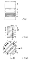
- Fig. 1 shows a piston 1 for a large two-stroke crosshead engine of the diesel type.
- the piston is connected with the crankshaft.
- the piston may, for example, have a diameter in the interval from 240 to 1000 mm.
- the piston has a number of axially separated ring grooves 2-4, in which piston rings can be mounted. Typically, four piston rings are mounted on the piston, but of course other numbers may be used, such as from two to eight piston rings.
- the piston shown in Fig. 1 has a relatively elongated piston portion, a so-called high top land 5, located above the ring groove for the top piston ring.
- This provides a certain protection of the top piston ring because the hot combustion gases first have to pass through an annular space between the inner surface of the cylinder and the high top land before they reach the piston ring.
- the high top land 5 may, for example, have an axial extent so that the top piston ring is located more than five times, preferably more than ten times the height of the piston ring below the uppermost point on the piston.
- the piston may also be formed as shown in Fig. 2, where the ring groove 2 for the top piston ring is close to the uppermost point of the piston.
- a rather large number of pressure relief passages 6 are located at the bottom of the ring groove 2 and connect it with the underlying ring groove 3.
- the ring groove 3 is connected with its underlying ring groove, and so forth down to the bottom ring groove 4.
- the pressure relief passages 6 may be bored in parallel with the centre axis 7 of the piston at a radius locating the passages at the bottom of the ring grooves, whereby the passages open out radially on the inside of the back surface of the piston ring, not shown, so that the outflowing leakage gas does not hit the piston ring directly.
- the bore sections 10 located below the bottom ring groove 4 are cut off by plugging 8, packing, closure by welding or in any other way that prevents gas from flowing through the sections 10 down below the piston.
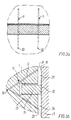
- pressure relief passages 11 are each manufactured as two passage segments 12, 13 located completely free of the associated ring groove (2 or 3), in which a piston ring 14 is mounted.
- the stresses in the piston ring 14 keep its outer ring surface 15 in contact with an inner surface 16 of a cylinder wall or a cylinder liner 17.
- the passage segment 12 has been bored obliquely downwards into the piston from the cylindrical outer surface 18 of the piston in the area above the ring groove
- the passage segment 13 has been bored obliquely upwards into the piston from the outer surface 18 in the area below the ring groove so that the segments 12, 13 have converging courses and intersect each other in a joint point of intersection 19 which may suitably be located radially on the inside of the ring groove.
- the embodiment can be modified by containing several passage segments for each passage.
- the piston 1 may, for example, be formed with an internal annular cavity located on the inside of the ring groove, and this annular cavity may constitute a segment in each passage so that the segments are simply bored from the outer surface of the piston into the internal annular cavity. Firstly, this means that the bores can be performed with less precision, because they do not need to hit the joint point of intersection, and secondly, leakage gas may be distributed between several passages via the annular cavity. Should such distribution be undesirable, the internal cavity may be divided in between each of the pressure relief passages.
- the third embodiment is seen in Fig. 4a in connection with the second ring groove 3 from the bottom, where pressure relief passages 21 extend from the bottom of the annular space 3' behind the back surface 22 of the piston ring and obliquely downwards out to the outer surface 18 of the piston below the piston ring 14.
- the piston ring 14 is pressed down into sealing contact with the lower surface 23 of the ring groove. Since the piston ring has a smaller ring height than the height of the ring groove there is a considerable clearance between the upper surface of the piston ring and the upper surface 24 of the ring groove, and this clearance causes the annular space 3' behind the piston ring to be under largely the same pressure as the annular space 25 above the piston ring, at the outer surface of the piston.
- the hot leakage gas flows from the annular space 3' through the passages 21 and out through the openings 20, wherefrom the gas jets pass across the annular space 26 below the piston ring and hit the inner surface 16 of the cylinder liner, and at the same time the pressure in the annular space 26 is being built up owing to the inflow of leakage gas.
- the outlet openings 20 are located on the outer surface of the piston and are therefore continuously moved in relation to the inner surface 16 so that the latter is not subjected to heat damage.
- annular space 3' is supplied with hot gas corresponding to the outflowing amount of leakage gas, but the supply takes place through the clearance between the upper ring surface and the upper surface 24, where the flow area is many times larger than the cross-sectional area of the passages 21, and the gas flows are correspondingly slower and calmer.
- the passages 21 may have different cross-sectional shapes, for example a simple circular cross-section as shown in Fig. 4b or an elongated cross-section as shown in Fig. 4c.
- the elongated cross-section has a larger area per passage, which results in fewer passages per ring groove for a specific total leakage area. It is possible to use passages with several different cross-sectional shapes in connection with the same ring groove.
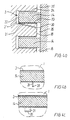
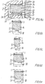
- the pressure relief passages 30 extend in parallel with the lower surface 23 of the ring groove from the bottom of the annular space 3' behind the piston ring and radially outwards to the opening 20 in the outer surface 18.
- the lower and upper surfaces of the ring groove are provided with a coating 31 of a hard material, such as chromium.
- the pressure relief passages 30 are upwardly open passages and have a larger passage depth d than the thickness t of the coating 31. This provides the advantage that the coating is only to a slight degree affected by the hot leakage gases.
- the passages 30 can be formed with different cross-sectional areas as described in connection with the passages 21.
- pressure relief passages 32 are provided in a separate piston portion 33 constituting the lower delimitation of the ring groove for the piston ring 14.
- the piston portion has a flange portion 34 placed in engagement with a recess at the bottom of the ring groove, whereby the piston portion is fastened to the remaining part of the piston.
- the piston portion 33 may be made of cast steel capable of enduring a long-term influence of substantially higher temperatures, normally at least 450°C, than the usual piston material, cast iron, which is more sensitive to temperatures.
- different piston portions may be mounted on the same piston base according to the actual power output chosen for the engine in which the piston is to be mounted. For example, the most suitable leakage area at a ring groove depends on, inter alia, the maximum pressure of the specific engine, and through a suitable choice of piston portion, the piston base can be adapted to the actual operating parameters of the engine.
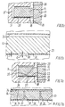
- the total cross-sectional area A tot of the pressure relief passages associated with the individual piston ring is in the interval from D 2 /68000 to D 2 /10000, and preferably in the interval from D 2 /30000 to D 2 /20000.
- the piston diameter D is about 600 mm
- a tot is in the interval from 5.29 to 36 mm 2 , preferably in the interval from 12 to 18 mm 2 .
- the area A tot is in the interval from 14.7 to 100 mm 2 , preferably in the interval from 33.3 to 50 mm 2 .
- the pressure relief passages 32 may have different cross-sectional shapes and sizes, and Fig. 6d shows a location of the passage at the top of the piston portion 33 corresponding to the embodiment shown in Fig. 5b. Moreover, as shown in Fig. 6e the passages 32 may be located at the lower surface of the piston portion 33, but this is not a preferred embodiment.
- the pressure relief passages comprise passage sections 35 which pass through the piston ring 14, preferably obliquely downwards, from the annular space 25 to an annular passage section 36 which is formed as an upwardly open recess in the upper surface 23 of the ring groove. From the passage section 36, the leakage gas flows via radially extending passage sections 37 to the outlet openings 20, from where the gas hits the inner surface 16 of the liner, slows down and causes a pressure increase in the annular space 26.
Landscapes
- Engineering & Computer Science (AREA)
- General Engineering & Computer Science (AREA)
- Mechanical Engineering (AREA)
- Chemical & Material Sciences (AREA)
- Combustion & Propulsion (AREA)
- Pistons, Piston Rings, And Cylinders (AREA)
- Hydraulic Motors (AREA)
Applications Claiming Priority (3)
| Application Number | Priority Date | Filing Date | Title |
|---|---|---|---|
| DK199700286A DK28697A (da) | 1997-03-14 | 1997-03-14 | Stempel til en forbrænmdingsmotor, navnlig en totakts krydshovedmotor af dieseltypen |
| DK28697 | 1997-03-14 | ||
| PCT/DK1998/000087 WO1998041749A1 (en) | 1997-03-14 | 1998-03-09 | A piston for a two-stroke crosshead engine of the diesel type |
Publications (2)
| Publication Number | Publication Date |
|---|---|
| EP0979352A1 EP0979352A1 (en) | 2000-02-16 |
| EP0979352B1 true EP0979352B1 (en) | 2002-10-30 |
Family
ID=8091850
Family Applications (1)
| Application Number | Title | Priority Date | Filing Date |
|---|---|---|---|
| EP98907895A Expired - Lifetime EP0979352B1 (en) | 1997-03-14 | 1998-03-09 | A two-stroke diesel engine piston |
Country Status (12)
| Country | Link |
|---|---|
| EP (1) | EP0979352B1 (da) |
| JP (1) | JP3362859B2 (da) |
| KR (1) | KR100370434B1 (da) |
| CN (1) | CN1083530C (da) |
| AU (1) | AU6609998A (da) |
| DE (1) | DE69809044T2 (da) |
| DK (1) | DK28697A (da) |
| ES (1) | ES2187007T3 (da) |
| NO (1) | NO994443L (da) |
| PL (1) | PL335806A1 (da) |
| RU (1) | RU2190773C2 (da) |
| WO (1) | WO1998041749A1 (da) |
Cited By (2)
| Publication number | Priority date | Publication date | Assignee | Title |
|---|---|---|---|---|
| DE102009028390B3 (de) * | 2009-08-10 | 2011-05-26 | Federal-Mogul Nürnberg GmbH | Kolben für einen Verbrennungsmotor |
| US20230034137A1 (en) * | 2021-07-28 | 2023-02-02 | Kabushiki Kaisha Kobe Seiko Sho (Kobe Steel, Ltd.) | Piston and reciprocating compressor |
Families Citing this family (19)
| Publication number | Priority date | Publication date | Assignee | Title |
|---|---|---|---|---|
| WO2002025090A1 (fr) * | 2000-09-20 | 2002-03-28 | Weimin Tang | Segment de feu monobloc solidaire de l'ensemble segment de piston et piston |
| DE10108246A1 (de) * | 2001-02-21 | 2002-09-19 | Gkn Sinter Metals Gmbh | Kolben mit Stützstegen für eine Kolben-Zylinder-Anordnung, insbesondere Stoßdämpferkolben |
| AT414270B (de) * | 2002-07-24 | 2006-10-15 | Ventrex Automotive Gmbh | Einrichtung zur verdichtung von gasen |
| AT414269B (de) * | 2002-07-24 | 2006-10-15 | Ventrex Automotive Gmbh | Einrichtung zur verdichtung von gasen |
| EP1431631A1 (de) * | 2002-12-18 | 2004-06-23 | Federal-Mogul Friedberg GmbH | Kolbenring |
| DE10319141A1 (de) * | 2003-04-28 | 2004-11-25 | Man B&W Diesel A/S | Kolben für einen Großmotor sowie Verfahren zur Herstellung einer Verschleißschutzschicht bei einem derartigen Kolben |
| US8746701B2 (en) * | 2010-05-27 | 2014-06-10 | GM Global Technology Operations LLC | Piston assembly |
| EP2551503A1 (de) * | 2011-07-25 | 2013-01-30 | Wärtsilä Schweiz AG | Kolben, Kolbenring und Ölverteilring für eine Hubkolbenbrennkraftmaschine |
| EP2639438A1 (en) * | 2012-03-13 | 2013-09-18 | Wärtsilä Schweiz AG | Piston and lubricant distribution device for reciprocating piston combustion engine |
| DE102012220464A1 (de) * | 2012-11-09 | 2014-05-28 | Federal-Mogul Burscheid Gmbh | Kolbenring mit einer periodisch variierenden Scheitelpunktlinie |
| CN107076302B (zh) * | 2014-09-08 | 2020-03-27 | 西港能源有限公司 | 活塞装置 |
| DE102015109826A1 (de) * | 2015-06-19 | 2016-12-22 | Federal-Mogul Burscheid Gmbh | Kolbenring mit Nutdichtung |
| DE102017103159B4 (de) * | 2017-02-16 | 2023-02-02 | Man Energy Solutions Se | Zylinder einer Brennkraftmaschine |
| DE102018106983B4 (de) * | 2018-03-23 | 2022-07-07 | Federal-Mogul Burscheid Gmbh | Kolbenring für Zweitaktmotoren mit einer Verschleißanzeige |
| CN111042944B (zh) * | 2019-12-20 | 2021-04-16 | 安徽工程大学 | 一种活塞缸套 |
| DE102020134381A1 (de) | 2020-12-21 | 2022-06-23 | NEUMAN & ESSER Deutschland GmbH & Co. KG Vertrieb und Anlagentechnik | Kompressor, Scheibenkörper und Dichtung |
| US20260036202A1 (en) * | 2022-08-10 | 2026-02-05 | Cummins Inc. | Piston assemblies and cylinders that control gas flow |
| DE102024106486A1 (de) * | 2024-03-06 | 2025-09-11 | Elringklinger Ag | Kolbendichtelement, Kolbendichtsystem für Kolbenverdichter und Verfahren zur Herstellung davon |
| CN120426209B (zh) * | 2025-07-09 | 2025-09-09 | 山东寿光鲁清石化有限公司 | 一种压缩机用迷宫活塞 |
Family Cites Families (8)
| Publication number | Priority date | Publication date | Assignee | Title |
|---|---|---|---|---|
| US4154207A (en) * | 1977-07-07 | 1979-05-15 | Ford Motor Company | Piston and ring for reducing HC emissions |
| GB2104621A (en) * | 1981-08-14 | 1983-03-09 | Exxon Research Engineering Co | Piston ring lubrication |
| JPH0248737B2 (ja) * | 1982-03-29 | 1990-10-26 | Mitsubishi Heavy Ind Ltd | Pisuton |
| SU1625637A1 (ru) * | 1988-03-02 | 1991-02-07 | Предприятие П/Я В-8221 | Устройство дл сборки полотнищ с ребрами жесткости |
| DK171422B1 (da) * | 1992-11-23 | 1996-10-21 | Man B & W Diesel Gmbh | Stempeltopring til en forbrændingsmotor |
| DE19520844A1 (de) * | 1994-06-20 | 1995-12-21 | Volkswagen Ag | Hubkolben-Brennkraftmaschine |
| DE19514918C2 (de) * | 1995-04-22 | 1999-01-07 | Mtu Friedrichshafen Gmbh | Kolben für Brennkraftmaschine |
| DK172822B1 (da) * | 1995-09-22 | 1999-08-02 | Man B & W Diesel As | Stempelring til et stempel i en forbrændingsmotor |
-
1997
- 1997-03-14 DK DK199700286A patent/DK28697A/da not_active Application Discontinuation
-
1998
- 1998-03-09 WO PCT/DK1998/000087 patent/WO1998041749A1/en not_active Ceased
- 1998-03-09 JP JP54003798A patent/JP3362859B2/ja not_active Expired - Fee Related
- 1998-03-09 KR KR10-1999-7008301A patent/KR100370434B1/ko not_active Expired - Fee Related
- 1998-03-09 RU RU99121855/06A patent/RU2190773C2/ru not_active IP Right Cessation
- 1998-03-09 AU AU66099/98A patent/AU6609998A/en not_active Abandoned
- 1998-03-09 EP EP98907895A patent/EP0979352B1/en not_active Expired - Lifetime
- 1998-03-09 PL PL98335806A patent/PL335806A1/xx unknown
- 1998-03-09 DE DE69809044T patent/DE69809044T2/de not_active Expired - Fee Related
- 1998-03-09 CN CN98803273A patent/CN1083530C/zh not_active Expired - Fee Related
- 1998-03-09 ES ES98907895T patent/ES2187007T3/es not_active Expired - Lifetime
-
1999
- 1999-09-13 NO NO994443A patent/NO994443L/no not_active Application Discontinuation
Cited By (3)
| Publication number | Priority date | Publication date | Assignee | Title |
|---|---|---|---|---|
| DE102009028390B3 (de) * | 2009-08-10 | 2011-05-26 | Federal-Mogul Nürnberg GmbH | Kolben für einen Verbrennungsmotor |
| US20230034137A1 (en) * | 2021-07-28 | 2023-02-02 | Kabushiki Kaisha Kobe Seiko Sho (Kobe Steel, Ltd.) | Piston and reciprocating compressor |
| US11668394B2 (en) * | 2021-07-28 | 2023-06-06 | Kobe Steel, Ltd. | Piston and reciprocating compressor |
Also Published As
| Publication number | Publication date |
|---|---|
| KR20000076207A (ko) | 2000-12-26 |
| WO1998041749A1 (en) | 1998-09-24 |
| AU6609998A (en) | 1998-10-12 |
| DE69809044T2 (de) | 2003-06-26 |
| NO994443L (no) | 1999-11-12 |
| RU2190773C2 (ru) | 2002-10-10 |
| JP3362859B2 (ja) | 2003-01-07 |
| ES2187007T3 (es) | 2003-05-16 |
| EP0979352A1 (en) | 2000-02-16 |
| CN1250505A (zh) | 2000-04-12 |
| PL335806A1 (en) | 2000-05-22 |
| KR100370434B1 (ko) | 2003-01-30 |
| DK28697A (da) | 1998-09-15 |
| DE69809044D1 (de) | 2002-12-05 |
| NO994443D0 (no) | 1999-09-13 |
| JP2000514156A (ja) | 2000-10-24 |
| CN1083530C (zh) | 2002-04-24 |
Similar Documents
| Publication | Publication Date | Title |
|---|---|---|
| EP0979352B1 (en) | A two-stroke diesel engine piston | |
| EP0851984B1 (en) | Piston ring and piston assembly in an internal combustion engine | |
| EP0397710B1 (en) | Engine including a piston member having a high top ring groove | |
| EP2499347B1 (en) | Piston with a skirt having oil flow slots and method of construction thereof | |
| EP0398993A1 (en) | MACHINE PISTON ASSEMBLY AND ITS FORGED PISTON WITH REFRIGERATOR. | |
| CN100368674C (zh) | 内燃机用单部件冷却通道活塞 | |
| WO2000004286A1 (en) | Piston having a tube to deliver oil for cooling a crown | |
| RU2153089C2 (ru) | Двигатель внутреннего сгорания, имеющий нагаросъемное кольцо в цилиндре (варианты) | |
| EP1077323B1 (en) | Cooled one piece piston and method for manufacture | |
| EP0742875B1 (en) | A piston top ring for an internal combustion engine | |
| CN101331308B (zh) | 内燃机活塞 | |
| KR101663345B1 (ko) | 내연 피스톤 엔진 조립체 | |
| RU2189479C2 (ru) | Гильза цилиндра для двигателя внутреннего сгорания дизельного типа (варианты) | |
| US4253435A (en) | Diesel engine and piston assembly therefor | |
| WO1997042406A1 (en) | A cylinder liner for an internal combustion engine | |
| EP0024890B1 (en) | Exhaust valve for an internal combustion engine | |
| US4941436A (en) | Cooling system for I.C.E. valve seat inserts | |
| US4991771A (en) | Fuel injection valve | |
| EP0004141B1 (en) | Diesel engine and piston assembly therefor | |
| KR100475811B1 (ko) | 실린더 라이너의 냉각 구조 | |
| HK1078915B (en) | Multi-part cooled piston for an internal combustion engine | |
| GB2368882A (en) | Valve seats for internal combustion engines formed by filling rebate in cylinder head with weld material |
Legal Events
| Date | Code | Title | Description |
|---|---|---|---|
| PUAI | Public reference made under article 153(3) epc to a published international application that has entered the european phase |
Free format text: ORIGINAL CODE: 0009012 |
|
| 17P | Request for examination filed |
Effective date: 19990831 |
|
| AK | Designated contracting states |
Kind code of ref document: A1 Designated state(s): BE DE ES FR GB IT NL SE |
|
| 17Q | First examination report despatched |
Effective date: 20001103 |
|
| RTI1 | Title (correction) |
Free format text: A TWO-STROKE DIESEL ENGINE PISTON |
|
| GRAG | Despatch of communication of intention to grant |
Free format text: ORIGINAL CODE: EPIDOS AGRA |
|
| RTI1 | Title (correction) |
Free format text: A TWO-STROKE DIESEL ENGINE PISTON |
|
| GRAG | Despatch of communication of intention to grant |
Free format text: ORIGINAL CODE: EPIDOS AGRA |
|
| GRAH | Despatch of communication of intention to grant a patent |
Free format text: ORIGINAL CODE: EPIDOS IGRA |
|
| GRAH | Despatch of communication of intention to grant a patent |
Free format text: ORIGINAL CODE: EPIDOS IGRA |
|
| GRAA | (expected) grant |
Free format text: ORIGINAL CODE: 0009210 |
|
| AK | Designated contracting states |
Kind code of ref document: B1 Designated state(s): BE DE ES FR GB IT NL SE |
|
| REG | Reference to a national code |
Ref country code: GB Ref legal event code: FG4D |
|
| REF | Corresponds to: |
Ref document number: 69809044 Country of ref document: DE Date of ref document: 20021205 |
|
| PGFP | Annual fee paid to national office [announced via postgrant information from national office to epo] |
Ref country code: GB Payment date: 20030226 Year of fee payment: 6 |
|
| PGFP | Annual fee paid to national office [announced via postgrant information from national office to epo] |
Ref country code: NL Payment date: 20030228 Year of fee payment: 6 |
|
| PGFP | Annual fee paid to national office [announced via postgrant information from national office to epo] |
Ref country code: SE Payment date: 20030304 Year of fee payment: 6 |
|
| PGFP | Annual fee paid to national office [announced via postgrant information from national office to epo] |
Ref country code: DE Payment date: 20030311 Year of fee payment: 6 |
|
| PGFP | Annual fee paid to national office [announced via postgrant information from national office to epo] |
Ref country code: FR Payment date: 20030314 Year of fee payment: 6 |
|
| PGFP | Annual fee paid to national office [announced via postgrant information from national office to epo] |
Ref country code: BE Payment date: 20030320 Year of fee payment: 6 |
|
| PGFP | Annual fee paid to national office [announced via postgrant information from national office to epo] |
Ref country code: ES Payment date: 20030321 Year of fee payment: 6 |
|
| ET | Fr: translation filed | ||
| REG | Reference to a national code |
Ref country code: ES Ref legal event code: FG2A Ref document number: 2187007 Country of ref document: ES Kind code of ref document: T3 |
|
| PLBE | No opposition filed within time limit |
Free format text: ORIGINAL CODE: 0009261 |
|
| STAA | Information on the status of an ep patent application or granted ep patent |
Free format text: STATUS: NO OPPOSITION FILED WITHIN TIME LIMIT |
|
| 26N | No opposition filed |
Effective date: 20030731 |
|
| PG25 | Lapsed in a contracting state [announced via postgrant information from national office to epo] |
Ref country code: GB Free format text: LAPSE BECAUSE OF NON-PAYMENT OF DUE FEES Effective date: 20040309 |
|
| PG25 | Lapsed in a contracting state [announced via postgrant information from national office to epo] |
Ref country code: SE Free format text: LAPSE BECAUSE OF NON-PAYMENT OF DUE FEES Effective date: 20040310 Ref country code: ES Free format text: LAPSE BECAUSE OF NON-PAYMENT OF DUE FEES Effective date: 20040310 |
|
| PG25 | Lapsed in a contracting state [announced via postgrant information from national office to epo] |
Ref country code: BE Free format text: LAPSE BECAUSE OF NON-PAYMENT OF DUE FEES Effective date: 20040331 |
|
| BERE | Be: lapsed |
Owner name: *MAN B & W DIESEL A/S Effective date: 20040331 |
|
| PG25 | Lapsed in a contracting state [announced via postgrant information from national office to epo] |
Ref country code: NL Free format text: LAPSE BECAUSE OF NON-PAYMENT OF DUE FEES Effective date: 20041001 Ref country code: DE Free format text: LAPSE BECAUSE OF NON-PAYMENT OF DUE FEES Effective date: 20041001 |
|
| GBPC | Gb: european patent ceased through non-payment of renewal fee | ||
| EUG | Se: european patent has lapsed | ||
| PG25 | Lapsed in a contracting state [announced via postgrant information from national office to epo] |
Ref country code: FR Free format text: LAPSE BECAUSE OF NON-PAYMENT OF DUE FEES Effective date: 20041130 |
|
| NLV4 | Nl: lapsed or anulled due to non-payment of the annual fee |
Effective date: 20041001 |
|
| REG | Reference to a national code |
Ref country code: FR Ref legal event code: ST |
|
| PG25 | Lapsed in a contracting state [announced via postgrant information from national office to epo] |
Ref country code: IT Free format text: LAPSE BECAUSE OF NON-PAYMENT OF DUE FEES Effective date: 20050309 |
|
| REG | Reference to a national code |
Ref country code: ES Ref legal event code: FD2A Effective date: 20040310 |