EP0978807A1 - Münzprüfer - Google Patents
Münzprüfer Download PDFInfo
- Publication number
- EP0978807A1 EP0978807A1 EP99905308A EP99905308A EP0978807A1 EP 0978807 A1 EP0978807 A1 EP 0978807A1 EP 99905308 A EP99905308 A EP 99905308A EP 99905308 A EP99905308 A EP 99905308A EP 0978807 A1 EP0978807 A1 EP 0978807A1
- Authority
- EP
- European Patent Office
- Prior art keywords
- coin
- discriminating
- exciting coil
- receiving coils
- determining authenticity
- Prior art date
- Legal status (The legal status is an assumption and is not a legal conclusion. Google has not performed a legal analysis and makes no representation as to the accuracy of the status listed.)
- Withdrawn
Links
Images


Classifications
-
- G—PHYSICS
- G07—CHECKING-DEVICES
- G07D—HANDLING OF COINS OR VALUABLE PAPERS, e.g. TESTING, SORTING BY DENOMINATIONS, COUNTING, DISPENSING, CHANGING OR DEPOSITING
- G07D5/00—Testing specially adapted to determine the identity or genuineness of coins, e.g. for segregating coins which are unacceptable or alien to a currency
- G07D5/08—Testing the magnetic or electric properties
-
- G—PHYSICS
- G07—CHECKING-DEVICES
- G07D—HANDLING OF COINS OR VALUABLE PAPERS, e.g. TESTING, SORTING BY DENOMINATIONS, COUNTING, DISPENSING, CHANGING OR DEPOSITING
- G07D5/00—Testing specially adapted to determine the identity or genuineness of coins, e.g. for segregating coins which are unacceptable or alien to a currency
- G07D5/005—Testing the surface pattern, e.g. relief
Definitions
- the present invention relates to a method of and apparatus for determining authenticity of coins by discriminating them, and more particularly to a method of and apparatus for determining authenticity of coins used in automatic vending machines, game machines, etc.
- Coin discrimination apparatus prevailing in recent years is an electronic type using induction coils.
- This type of coin discrimination apparatus generally utilizes the falling of coins due to their own weight and is provided with a passage for guiding a coin inserted from a coin slot.
- a plurality of sets of induction coils are arranged along the passage to produce electromagnetic fields excited by respective different frequencies.
- Inspection of coins is performed by detecting an amount of electrical change (change in frequency, voltage or phase) derived due to the interaction between the electromagnetic field and a coin when the coin passes through the electromagnetic field, to thereby inspect the authenticity of the coin.
- a 500-yen coin used in Japan and a 500-won coin used in South Korea are almost identical with each other in material and outside diameter, and differ from each other in that a 500-won coin has a slightly greater thickness.
- a 500-won coin is machined and is used as a 500-yen coin, it is difficult to discriminate the two from each other with the conventional method in which the thickness, outside diameter and material of coins are inspected to determine the authenticity thereof.
- optical apparatus has a problem that the authenticity determination of coins can be adversely affected by adhesion of dust or the like, and is also large in size and expensive because of its complicated structure.
- the object of the present invention is to provide a method and apparatus for determining authenticity of coins whereby coins can be discriminated from each other with high accuracy.
- a coin authenticity determining method of the present invention comprises the steps of: arranging an exciting coil and a receiving coil in the vicinity of a coin passage so that the exciting coil and the receiving coil are electromagnetically connected with each other; exciting the exciting coil to produce an electromagnetic field with such a frequency that an influence of a demagnetizing field caused by eddy current induced on a surface of the coin when the coin passes the electromagnetic field is detected by the receiving coil, and detecting the electromagnetic field influenced by the demagnetizing field as an electromotive force signal by the receiving coil; and discriminating the coin based on the electromotive force signal detected by the receiving coil.
- the surface of the coin passing through the coin passage and the receiving coil should preferably be close to each other, and therefore the coin passage is formed such that the coin is inclined to one side of the coin passage where the exciting coil and the receiving coil are arranged.
- the degree of penetration of electromagnetic field into a coin varies depending on the material of the coin and excitation frequency.
- an excitation frequency with which a difference in surface irregularity pattern of coins appears well as a difference of the signal from the receiving coil varies depending on the material of coins to be discriminated. Accordingly, the frequency at which the exciting coil is to be excited is selected in accordance with material of coins to be discriminated.
- authenticity of coins is determined by using an exciting coil arranged in the vicinity of one side of a coin passage inclining at a predetermined angle so that magnetic poles of the exciting coil faces the coin passage, two receiving coils having substantially identical characteristics and arranged in the vicinity of the coin passage so that the receiving coils are electromagnetically connected with the exciting coil, exciting means for exciting the exciting coil at a predetermined frequency to produce an electromagnetic field, bridge circuit means including the receiving coils, differential amplifier means connected to the bridge circuit means, detector means connected to the differential amplifier means, and determining means connected to the detector means, for comparing a signal obtained when a coin passes the electromagnetic field with a feature of a predetermined denomination stored in advance and determining that the coin is authentic if the signal is within a predetermined allowable range with respect to the feature.
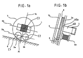
- FIGS. 1a, 1b and 2 one embodiment of the present invention will be described.
- a detector for discriminating a coin 3 comprises one exciting coil 1 and two receiving coils 2a and 2b, and is arranged in contact with one side wall 7a of a coin passage 6.
- the coin passage 6 is sloped at a predetermined angle to allow the coin 3 to roll down while being guided thereby and comprises a coin rail 4 arranged at the bottom thereof and a pair of passage walls 7a and 7b.
- the passage walls 7a and 7b are, as shown in FIG. 1b, inclined with respect to the vertical direction so that the coin 3 may roll down while being inclined toward the passage wall 7a.
- the surface of the coin rail 4, on which the coin is guided is inclined in the direction in which the passage walls 7a and 7b are inclined so that the coin 3 passing thereon may be inclined toward the passage wall 7a.
- Each of the two receiving coils 2a and 2b comprises, as shown in FIG. 5b, a drum type core 43 and a coil 44 wound around the core 43.
- the receiving coils 2a and 2b are arranged above the coin rail 4 at a predetermined distance from each other such that a line 5a connecting the centers of the coils 2a and 2b is substantially parallel with the coin rail 4.
- the exciting coil 1 comprises, as shown in FIG. 5a, a ⁇ -shaped core 40 made of a magnetic material and a coil 41 wound around the core 40.
- the exciting coil 1 is arranged above the receiving coils 2a and 2b such that the center C3 of the core 40 thereof is located on a line 5c which is perpendicular to the line 5a connecting the centers C1 and C2 of the receiving coils 2a and 2b and which passes through the middle point M of the line segment C1C2 and also that a line 5b connecting the centers of two pole faces 40a thereof is substantially parallel with the coin rail 4.
- the core 40 is arranged such that the pole faces 40a thereof are parallel with the face of the coin 3 passing thereby.
- reference numerals 42 and 45 each denote a lead wire.
- the exciting coil 1 and the receiving coils 2a and 2b arranged as described above are electromagnetically coupled by means of an electromagnetic field produced by excitation of the exciting coil 1.
- an oscillation circuit 11 outputs to an output terminal thereof a rectangular wave signal of predetermined frequency generated by an MPU (microprocessor unit) or the like, for example.
- the output of the oscillation circuit 11 is connected to an excitation driver circuit 12, the output of which is in turn connected to the exciting coil 1 to excite same. Consequently, in accordance with the output signal of the excitation driver circuit 12, the exciting coil 1 produces an electromagnetic field in the vicinity thereof.
- an electromotive force corresponding to the strength of the electromagnetic field produced by the exciting coil 1 is generated.
- the exciting coil 1 and the receiving coils 2a and 2b are preferably arranged for inspection so as to be close to the face of the coin 3, as mentioned above.
- the magnetic poles of the exciting coil 1 are arranged in the vicinity of the receiving coils 2a and 2b, a change of the demagnetizing current induced when the coin 3 is acted upon by the electromagnetic field produced by these magnetic poles can be acquired at a location near the magnetic poles.
- the demagnetizing current induced due to the skin effect is noticeably observed near the outer periphery of the coin, but in cases where coins have large surface irregularity, the region of coins where a change of the demagnetizing current can be detected is not particularly limited to the outer peripheral region alone.
- a corresponding alternating voltage signal is generated in a bridge circuit 13 including the receiving coils 2a and 2b, and is output to a differential amplifier 14.
- the differential amplifier 14 amplifies the alternating voltage signal generated by the bridge circuit 13 and outputs the thus-amplified signal to a detector circuit 15.
- the detector circuit 15 which is supplied with the alternating voltage signal amplified by the differential amplifier 14, generates a direct voltage signal corresponding to the detection signal and outputs same to a determination circuit 16.
- the direct voltage signal is supplied to an AD convener 17 in the determination circuit 16, in which the signal is converted to a digital signal of corresponding voltage, which signal is then output to a signal inspection circuit 18 in the determination circuit 16.
- the signal inspection circuit 18 determines whether or not the coin 3 has a given feature, and outputs the result of determination to an output terminal 19.
- the output of the signal inspection circuit 18 is used to drive a deflector solenoid, described later, or a coin counter or the like, not shown.
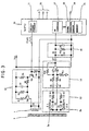
- FIG. 3 shows details of the circuits appearing in the block diagram of FIG. 2.
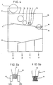
- FIG. 4 is a front view of a coin inspection apparatus using the detection coil for detecting surface irregularity patterns
- FIGS. 5a and 5b are a front view and a sectional view, respectively, showing details of the coil arrangement.
- the oscillation circuit 11 is constructed with the use of frequency divider means or the like which is connected to an MPU 20 for dividing a reference clock signal generated therein.
- the exciting coil 1 is connected in parallel with a capacitor C1 to form an LC parallel resonance circuit so that resonance thereof may occur in the vicinity of the predetermined frequency output from the oscillation circuit 11.
- the excitation driver circuit 12 comprises a transistor TR1 and resistors R3 and R4 connected to one another to perform switching operation; an integrating circuit made up of a resistor R5, a capacitor C4 and a resistor R6 for converting the rectangular wave output from the oscillation circuit 11 into a waveform approximate to a triangular wave; and a driver circuit including a transistor TR2 connected to the exciting coil 1 constituting the LC parallel resonance circuit, and a resistor R7.
- the bridge circuit 13 comprises a capacitor C2 connected in parallel with the receiving coil 2a, a capacitor C3 connected in parallel with the receiving coil 2b, and resistors R1 and R2.
- the differential amplifier 14 comprises capacitors C5 and C6 connected to the output of the bridge circuit 13 in an AC coupling fashion, an operational amplifier A1, and resistors R8, R10 and R9, R11 connected so as to determine the gain of the operational amplifier.
- the detector circuit 15 comprises a rectifier circuit (voltage multiplying rectifier circuit) including diodes D1 and D2 connected to a coupling capacitor C7 connected to the output of the differential amplifier 14, and an integrating circuit including a resistor R12 and a capacitor C8.
- a rectifier circuit voltage multiplying rectifier circuit
- diodes D1 and D2 connected to a coupling capacitor C7 connected to the output of the differential amplifier 14, and an integrating circuit including a resistor R12 and a capacitor C8.
- the AD converter 17 and the signal inspection circuit 18 of the determination circuit 16 are constituted by using the MPU 20 (microprocessor unit).
- the oscillation circuit 11 outputs a rectangular wave signal with a predetermined frequency, and to detect a difference of the surface irregularity pattern of the coin 3 with high sensitivity, the frequency of the signal is preferably selected such that the electromagnetic field penetrates into the surface region of the irregularity pattern of the coin, but not up to the central region thereof, and that the influence of the demagnetizing field caused by eddy current is noticeable.
- the frequency to be employed varies depending on the material of coins to be discriminated, and in the case of discrimination between 5-cent coin of the U.S.A. and 5-centesimo coin of Panama, both made of cupronickel, the excitation frequency of the exciting coil 1 is preferably 70 kHz to 90 kHz. An experiment according to this invention, described later, was conducted with the frequency set at 90 kHz.
- the frequency at which the exciting coil 1 is to be excited is selected in accordance with the material of coins to be detected. Specifically, using coins having an identical outside diameter but different thicknesses, the voltage detected by the receiving coils 2a and 2b is measured with the excitation frequency successively varied, and that frequency with which a large change of the detected voltage is caused by the difference in thickness of coins is selected as the excitation frequency.
- cupronickel for example, it was confirmed by experiment that, with the excitation frequency set at about 70 kHz to 90 kHz, the detected voltage showed the largest change in response to the difference in thickness. With frequencies higher than or lower than a frequency band of 70 kHz to 90 kHz, change of the detected voltage in response to the difference in thickness of coins gradually lessens as the frequency becomes remoter from the frequency band. To discriminate coins by difference in thickness, that is, by difference in surface irregularity pattern of coins, the above excitation frequency of 70 kHz to 90 kHz is preferred for cupronickel coins.
- an excitation frequency of about 7 kHz to 10 kHz causes the output voltage to greatly vary in response to the difference in thickness of coins. Accordingly, in the case of discriminating coins made of brass by their surface irregularity pattern, the discrimination can be efficiently carried out by using the excitation frequency of 7 kHz to 10 kHz.
- the rectangular wave signal output from the oscillation circuit 11 is integrated to be converted into a waveform approximate to a triangular wave by the integrating circuit composed of the resistor R5, the capacitor C4 and the resistor R6, so that the exciting coil 1 is excited by the approximated triangular wave signal.
- the LC resonance circuit constituted by the exciting coil 1 and the capacitor C1 resonates with the aforementioned frequency, and as a result, the exciting coil 1 is driven at both ends by a sinusoidal wave.
- the resonance frequency of the LC resonance circuit constituted by the receiving coil 2a and the capacitor C2 and the resonance frequency of the LC resonance circuit constituted by the receiving coil 2b and the capacitor C3 are set so as to be substantially equal to the oscillation frequency output from the oscillation circuit 11. Accordingly, the impedances Z1 and Z2 are substantially equal to each other, and the signal appearing between the aforementioned two junction points is a voltage signal induced by the difference between the currents i1 and i2.
- the differential amplifier 14 amplifies the alternating voltage signal input thereto from the bridge circuit 13 to obtain a desired alternating voltage signal, which is then output to the detector circuit 15.
- the detector circuit 15 which is supplied with the alternating voltage signal output from the differential amplifier 14, performs detection and rectification of the signal by means of the diode D1, and then converts the signal to a direct voltage signal corresponding to the output of the bridge circuit 13 by means of the integrating circuit constituted by the resistor R12 and the capacitor C8.
- the AD converter 17 is implemented by an AD converter of successive approximation and conversion type built in the MPU 20 and having a resolution of, for example, 8 bits.
- the AD converter 17 samples the analog direct voltage signal from the detector circuit 15 at predetermined intervals of time and converts same to a digital signal corresponding to the output of the bridge circuit 13, the resulting digital signal train being output to the signal inspection circuit 18.
- the signal inspection circuit 18, which is thus supplied with the digital signal train on an amplitude axis from the AD converter 17, temporarily stores the signal train in a memory such as RAM, obtains a statistic based on the digital signal train temporarily stored in the RAM and data train of a corresponding denomination stored beforehand in the memory 21, then compares the obtained statistic with a predetermined value stored in advance in the memory 21 to determine whether or not the coin in question has a given feature, and outputs the result of inspection to the output terminal 19.
- a memory such as RAM
- N represents the number of samples
- variable Xi is a sampling value, that is, a value of the aforementioned digital signal train obtained through measurement of a coin to be detected
- variable Yi is a statistical value obtained through sampling/measurement of coins of acceptable denomination with the use of an apparatus according to this invention.
- Xa and Ya are average values of the respective variables.
- the deviation (Yi - Ya) between the sampling value Yi of acceptable denomination and its average value Ya in the sum of deviation cross products in the numerator of equation (1) and the square root of the sum of squares of the deviation between the sampling value Yi and its average value Ya in the denominator of equation (1) may be calculated in advance and stored in the memory 21, in which case the speed of execution of the subsequent process can be greatly increased.
- the absolute value of the correlation coefficient r obtained by equation (1) falls within a range of 0 ⁇
- the above predetermined value for authenticity judgment is set to a value smaller than and close to "1" for coins to be discriminated, and when a correlation coefficient r greater than the set value is derived, the coin in question is judged to be a genuine coin.
- FIG. 6 shows the characteristics of the representative coins
- FIG. 7 shows comparison of data of the coins.
- 5-cent coin of the U.S.A. and 5-centesimo coin of Panama as representative coins, are very alike in material (cupronickel), diameter, and thickness. The two coins, when observed visually, are different from each other only in their surface design.
- FIG. 6 is a characteristic diagram showing the results of measurement of these coins by means of the apparatus of this invention wherein the exciting coil 1 was excited at an excitation frequency of 90 kHz.
- reference numeral 50 (thick line) represents the characteristic curve of 5-cent coin of the U.S.A.
- 51 represents the characteristic curve of 5-centesimo coin of Panama.
- difference in characteristics between these two coins appears in the first and last peaks. This peak difference arose presumably because a demagnetizing field characterized by the irregularity of surface pattern of the coin was produced by eddy current induced on the coin surface and was detected as a subtle difference in electromotive force generated in the aforementioned two receiving coils. The above difference could not be detected by conventional techniques.
- FIGS. 4 and 2 the operation of an apparatus 30 for inspecting authenticity of coins will be described in detail.
- a coin 3 inserted from a coin slot 31 falls naturally due to its own weight onto the coin rail 4 arranged under the coin slot 31.
- the coin 3 thus dropped on the coin rail 4 rolls down through the coin passage 6 (FIG. 1b) in a downstream direction away from the coin slot 31.
- the coin 3 passes by an outside diameter detection coil 32, a material detection coil 33, and a surface irregularity pattern detection coil including the exciting coil 1 and the receiving coils 2a and 2b.
- the apparatus 30 inspects the authenticity of the coin 3 while the coin 3 passes the individual detection coils.
- a deflector solenoid 35 is driven in accordance with the signal output to the output terminal 19, to actuate a gate 34 such that the coin 3 is guided to a genuine-coin passage, not shown.
- the gate 34 is not actuated, so that the coin 3 is guided to a false-coin passage, not shown, to be let out from an outlet, not shown.
- the coin 3 When the coin 3 is genuine and thus introduced to the genuine-coin passage, it continues to fall naturally and drops onto a coin rail 36.
- the coin 3 which has dropped onto the coin rail 36 is then sorted by conventionally known sorting means, not shown, according to denomination, and let out from a corresponding one of outlets A, B, C and D provided for respective denominations.
- Step 100 when the power supply to the apparatus is switched on, initial settings such as input/output settings in the MPU 20 are carried out in Step 100.
- Step 101 a process for determining whether or not a coin has been inserted in the apparatus is executed in Step 101 by using the signal from the detection coil. If it is judged in Step 101 that a coin has been inserted, the program proceeds to an AD conversion process in Step 102. On the other hand, if it is judged in Step 101 that a coin has not been inserted yet, a standby process is repeated until arrival of a coin.
- Step 101 When it is judged in Step 101 that a coin has been inserted, the AD conversion process is executed in Step 102, as mentioned above.
- the AD conversion process of Step 102 On reception of the signal indicative of arrival of a coin at the detection coil, the AD conversion process of Step 102 starts to sample the output signal of the detector circuit 15, which is the signal from the receiving coils 2a and 2b of the detection coil for detecting surface irregularity pattern.
- the result of sampling is temporarily stored in memory such as RAM in the MPU 20 and the program proceeds to a computation process in Step 103.
- a correlation coefficient r is obtained using the value of the digital signal train temporarily stored in the memory and the statistic of acceptable coin stored beforehand in the memory 21, in accordance with the aforementioned equation (1), and the program proceeds to an authenticity judgment process in Step 105.
- Step 105 the correlation coefficient obtained in the computation process of Step 103 is compared with the predetermined value of acceptable coin stored in advance, and if the relationship, correlation coefficient r > predetermined value, is fulfilled, the coin in question is judged to be genuine, and the program proceeds to a genuine-coin process in Step 106. If, on the other hand, it is judged that the relationship, correlation coefficient r ⁇ predetermined value, is fulfilled, the coin in question is judged to be false; in which case the program executes a false-coin process in Step 104 and returns to the standby loop.
- Step 106 a process of outputting a genuine-coin signal, a denomination signal, etc. is executed in accordance with the result of authenticity judgment, whereupon the program returns to the standby loop.
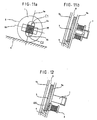
- FIGS. 9a and 9b show the arrangement of a detector for detecting surface irregularity pattern according to a second embodiment of the present invention.
- the second embodiment differs from the first embodiment described above only in that the exciting coil 1 and the receiving coils 2a and 2b are arranged such that the line 5b connecting the centers of the pole faces 40a at the longitudinally opposite end portions of the ⁇ -shaped core 40 of the exciting coil 1 is perpendicular to the line 5a connecting the centers of the receiving coils 2a and 2b and passes through the middle point M between the centers C1 and C2 of the receiving coils 2a and 2b.
- the operation and effects of the second embodiment are identical with those of the first embodiment, and therefore, description thereof is omitted.
- FIGS. 10a and 10b show the arrangement of another detector for detecting surface irregularity pattern according to a third embodiment of the present invention.
- the third embodiment differs from the above-described first embodiment only in that the line 5a connecting the centers of the receiving coils 2a and 2b is shifted in the vertical direction with respect to the coin rail 4 on which the coin 3 rolls down, so as to pass the central portion of the coin 3 to be detected.
- the receiving coils 2a and 2b are arranged at a location corresponding to the central portion of the coin 3 to be detected, and accordingly, the detection value varies in accordance with difference in surface irregularity pattern of the central portion of the coin 3, so that the arrangement is suited for judging authenticity of coins by determining whether or not the coin has a hole in the center thereof.
- FIGS. 11a and 11b show the arrangement of still another detector for detecting surface irregularity pattern according to a fourth embodiment of the present invention.
- the fourth embodiment differs from the above-described first embodiment in that the side-by-side arrangement of the receiving coils is rotated by 90 degrees so that the line 5a connecting the centers of the receiving coils 2a and 2b may be perpendicular to the line 5b connecting the centers of the pole faces of the core of the exciting coil 1 and pass through the center of the exciting coil 1.
- the receiving coils 2a and 2b are arranged at a location corresponding to the central portion of the coin to be detected, and therefore, the arrangement of the fourth embodiment is suited for judging authenticity of coins by discriminating between presence and absence of change in the surface irregularity pattern of the central portion thereof.
- the position where the receiving coils 2a and 2b are arranged may be changed in accordance with difference in surface irregularity pattern of coins whose authenticity is to be determined (depending on whether the difference in surface irregularity pattern exists in the central-portion, e.g. presence/absence of a hole, or in the peripheral portion of the coin).
- the exciting coil 1 is excited at a frequency such that the electromagnetic field produced penetrates only into the surface region of the coin but not up to the central region of same, and the influence of a demagnetizing field caused by eddy current induced in the vicinity of the surface of the coin is measured. Accordingly, the surfaces of the receiving coils 2a and 2b facing the coin should desirably be as close to the coin surface as possible.
- a portion of the passage wall 7a where the receiving coils 2a and 2b are arranged may be made of a material 200 having high magnetic permeability, so that the receiving coils 2a and 2b may be virtually located closer to the surface of the coin.
- the exciting coil 1 having a ⁇ -shaped core is used, but cores of any other suitable shape such as a U-shaped core may be used without departing from the spirit and scope of this invention.
- the present invention since the surface irregularity patterns of coins can be detected, it is possible to provide at low cost a small-sized, high-performance coin inspection apparatus capable of dealing with a diversity of coins.
Landscapes
- Physics & Mathematics (AREA)
- General Physics & Mathematics (AREA)
- Testing Of Coins (AREA)
Applications Claiming Priority (3)
| Application Number | Priority Date | Filing Date | Title |
|---|---|---|---|
| JP06037798A JP3660496B2 (ja) | 1998-02-26 | 1998-02-26 | コインの真贋性を検査する方法及び装置 |
| JP6037798 | 1998-02-26 | ||
| PCT/JP1999/000881 WO1999044176A1 (fr) | 1998-02-26 | 1999-02-25 | Procede et dispositif permettant de detecter une fausse piece de monnaie |
Publications (2)
| Publication Number | Publication Date |
|---|---|
| EP0978807A1 true EP0978807A1 (de) | 2000-02-09 |
| EP0978807A4 EP0978807A4 (de) | 2002-03-06 |
Family
ID=13140398
Family Applications (1)
| Application Number | Title | Priority Date | Filing Date |
|---|---|---|---|
| EP99905308A Withdrawn EP0978807A4 (de) | 1998-02-26 | 1999-02-25 | Münzprüfer |
Country Status (7)
| Country | Link |
|---|---|
| EP (1) | EP0978807A4 (de) |
| JP (1) | JP3660496B2 (de) |
| KR (1) | KR100562857B1 (de) |
| AU (1) | AU729021B2 (de) |
| CA (1) | CA2288297C (de) |
| MY (1) | MY123288A (de) |
| WO (1) | WO1999044176A1 (de) |
Cited By (3)
| Publication number | Priority date | Publication date | Assignee | Title |
|---|---|---|---|---|
| EP1241636A3 (de) * | 2001-03-15 | 2004-06-30 | Glory Ltd. | Münzprüfer für Münzen aus mehreren Materialien |
| EP1503170A1 (de) * | 2002-04-26 | 2005-02-02 | Azuma Systems Co., Ltd. | Münzformerkennungsverfahren, münzidentifikationssensor und münzidentifikationseinrichtung |
| EP2040227A3 (de) * | 2007-09-20 | 2010-01-13 | National Rejectors, Inc. GmbH | Verfahren zum Prüfen von Münzen |
Families Citing this family (4)
| Publication number | Priority date | Publication date | Assignee | Title |
|---|---|---|---|---|
| JP3773689B2 (ja) * | 1999-03-17 | 2006-05-10 | 株式会社日本コンラックス | コイン検査方法及び装置 |
| KR100390251B1 (ko) * | 1999-10-06 | 2003-07-04 | 가부시키가이샤 닛폰 콘락스 | 코인 검사방법 및 장치 |
| US6340082B1 (en) * | 1999-10-22 | 2002-01-22 | Japan Tobacco Inc. | Coin discriminating apparatus |
| JP7443733B2 (ja) * | 2019-11-28 | 2024-03-06 | 沖電気工業株式会社 | 硬貨認識装置、及び、当該硬貨認識装置を用いる硬貨取扱装置 |
Citations (3)
| Publication number | Priority date | Publication date | Assignee | Title |
|---|---|---|---|---|
| US4705154A (en) * | 1985-05-17 | 1987-11-10 | Matsushita Electric Industrial Co. Ltd. | Coin selection apparatus |
| US5458225A (en) * | 1991-09-28 | 1995-10-17 | Anritsu Corporation | Coin discriminating apparatus |
| EP0731429A2 (de) * | 1995-03-07 | 1996-09-11 | Cummins-Allison Corporation | Münzprüfsensor und Münzbehandlungssystem |
Family Cites Families (6)
| Publication number | Priority date | Publication date | Assignee | Title |
|---|---|---|---|---|
| US3870137A (en) | 1972-02-23 | 1975-03-11 | Little Inc A | Method and apparatus for coin selection utilizing inductive sensors |
| JPS6180491A (ja) * | 1984-09-28 | 1986-04-24 | 株式会社日本コンラックス | 硬貨検査装置 |
| JPH0589319A (ja) * | 1991-09-26 | 1993-04-09 | Tdk Corp | コインセンサ |
| JP2964057B2 (ja) * | 1992-10-09 | 1999-10-18 | アンリツ株式会社 | 硬貨判別装置の硬貨センサ |
| JP3478602B2 (ja) * | 1994-07-28 | 2003-12-15 | 株式会社日本コンラックス | コイン検査方法およびその装置 |
| JPH08212416A (ja) * | 1995-02-03 | 1996-08-20 | Anritsu Corp | 硬貨判別装置 |
-
1998
- 1998-02-26 JP JP06037798A patent/JP3660496B2/ja not_active Expired - Fee Related
-
1999
- 1999-02-25 CA CA002288297A patent/CA2288297C/en not_active Expired - Fee Related
- 1999-02-25 WO PCT/JP1999/000881 patent/WO1999044176A1/ja active IP Right Grant
- 1999-02-25 EP EP99905308A patent/EP0978807A4/de not_active Withdrawn
- 1999-02-25 KR KR1019997008409A patent/KR100562857B1/ko not_active IP Right Cessation
- 1999-02-25 AU AU25494/99A patent/AU729021B2/en not_active Ceased
- 1999-02-26 MY MYPI99000723A patent/MY123288A/en unknown
Patent Citations (3)
| Publication number | Priority date | Publication date | Assignee | Title |
|---|---|---|---|---|
| US4705154A (en) * | 1985-05-17 | 1987-11-10 | Matsushita Electric Industrial Co. Ltd. | Coin selection apparatus |
| US5458225A (en) * | 1991-09-28 | 1995-10-17 | Anritsu Corporation | Coin discriminating apparatus |
| EP0731429A2 (de) * | 1995-03-07 | 1996-09-11 | Cummins-Allison Corporation | Münzprüfsensor und Münzbehandlungssystem |
Non-Patent Citations (1)
| Title |
|---|
| See also references of WO9944176A1 * |
Cited By (5)
| Publication number | Priority date | Publication date | Assignee | Title |
|---|---|---|---|---|
| EP1241636A3 (de) * | 2001-03-15 | 2004-06-30 | Glory Ltd. | Münzprüfer für Münzen aus mehreren Materialien |
| EP1503170A1 (de) * | 2002-04-26 | 2005-02-02 | Azuma Systems Co., Ltd. | Münzformerkennungsverfahren, münzidentifikationssensor und münzidentifikationseinrichtung |
| EP1503170A4 (de) * | 2002-04-26 | 2006-06-14 | Azuma Systems Co Ltd | Münzformerkennungsverfahren, münzidentifikationssensor und münzidentifikationseinrichtung |
| EP2040227A3 (de) * | 2007-09-20 | 2010-01-13 | National Rejectors, Inc. GmbH | Verfahren zum Prüfen von Münzen |
| US7708130B2 (en) | 2007-09-20 | 2010-05-04 | National Rejectors, Inc. Gmbh | Method for testing coins |
Also Published As
| Publication number | Publication date |
|---|---|
| JP3660496B2 (ja) | 2005-06-15 |
| MY123288A (en) | 2006-05-31 |
| CA2288297C (en) | 2004-04-27 |
| KR20000076308A (ko) | 2000-12-26 |
| AU2549499A (en) | 1999-09-15 |
| KR100562857B1 (ko) | 2006-03-24 |
| EP0978807A4 (de) | 2002-03-06 |
| AU729021B2 (en) | 2001-01-25 |
| WO1999044176A1 (fr) | 1999-09-02 |
| CA2288297A1 (en) | 1999-09-02 |
| JPH11250305A (ja) | 1999-09-17 |
Similar Documents
| Publication | Publication Date | Title |
|---|---|---|
| US4488116A (en) | Inductive coin sensor for measuring more than one parameter of a moving coin | |
| JP2567654B2 (ja) | 硬貨選別方法および装置 | |
| EP0970445B1 (de) | Münzprüfer | |
| US6325197B1 (en) | Method and device for checking coin for forgery | |
| US7108120B2 (en) | Coin inspection method and apparatus therefor | |
| EP1451781B1 (de) | Münzunterscheidungsvorrichtung, in der frequenzen von wirbelströmen gemessen werden | |
| US6640955B1 (en) | Coin inspection method and device | |
| EP0978807A1 (de) | Münzprüfer | |
| EP1123537B1 (de) | Verfahren und vorrichtung zum prüfen von bimetallischen münzen | |
| JP4094215B2 (ja) | コイン検査装置 | |
| JP2000268221A (ja) | コイン検査装置 | |
| EP0878783B1 (de) | Münzprüfsystem | |
| JP2001126104A (ja) | コイン検査方法および装置 | |
| JP4672912B2 (ja) | コインセンサ及びコイン検査装置 | |
| JPH1131249A (ja) | コインの真贋性を検査する方法および装置 | |
| JPH0374438B2 (de) | ||
| JPS6063691A (ja) | 硬貨判別装置 |
Legal Events
| Date | Code | Title | Description |
|---|---|---|---|
| PUAI | Public reference made under article 153(3) epc to a published international application that has entered the european phase |
Free format text: ORIGINAL CODE: 0009012 |
|
| 17P | Request for examination filed |
Effective date: 19991026 |
|
| AK | Designated contracting states |
Kind code of ref document: A1 Designated state(s): DE FR GB IT |
|
| A4 | Supplementary search report drawn up and despatched |
Effective date: 20020117 |
|
| AK | Designated contracting states |
Kind code of ref document: A4 Designated state(s): DE FR GB IT |
|
| 17Q | First examination report despatched |
Effective date: 20041007 |
|
| RAP1 | Party data changed (applicant data changed or rights of an application transferred) |
Owner name: KABUSHIKI KAISHA NIPPON CONLUX |
|
| STAA | Information on the status of an ep patent application or granted ep patent |
Free format text: STATUS: THE APPLICATION IS DEEMED TO BE WITHDRAWN |
|
| 18D | Application deemed to be withdrawn |
Effective date: 20090901 |