EP0978632A1 - Turbomachine avec aubes intermédiaires divisant le courant - Google Patents
Turbomachine avec aubes intermédiaires divisant le courant Download PDFInfo
- Publication number
- EP0978632A1 EP0978632A1 EP98810756A EP98810756A EP0978632A1 EP 0978632 A1 EP0978632 A1 EP 0978632A1 EP 98810756 A EP98810756 A EP 98810756A EP 98810756 A EP98810756 A EP 98810756A EP 0978632 A1 EP0978632 A1 EP 0978632A1
- Authority
- EP
- European Patent Office
- Prior art keywords
- blade
- full
- channel
- flow
- blades
- Prior art date
- Legal status (The legal status is an assumption and is not a legal conclusion. Google has not performed a legal analysis and makes no representation as to the accuracy of the status listed.)
- Withdrawn
Links
Images


Classifications
-
- F—MECHANICAL ENGINEERING; LIGHTING; HEATING; WEAPONS; BLASTING
- F01—MACHINES OR ENGINES IN GENERAL; ENGINE PLANTS IN GENERAL; STEAM ENGINES
- F01D—NON-POSITIVE DISPLACEMENT MACHINES OR ENGINES, e.g. STEAM TURBINES
- F01D5/00—Blades; Blade-carrying members; Heating, heat-insulating, cooling or antivibration means on the blades or the members
- F01D5/12—Blades
- F01D5/14—Form or construction
- F01D5/141—Shape, i.e. outer, aerodynamic form
- F01D5/145—Means for influencing boundary layers or secondary circulations
Definitions
- the invention relates to devices for reducing the losses of a fluid flow in bladed flow channels of turbomachinery, especially in steam or Gas turbines.
- the efficiency of a turbomachine, especially one, that is common today Steam or gas turbine, to further increase it is central to that the flow through the bladed flow channels of the turbomachine To reduce flow losses of the fluid.
- a row of blades arranged on the circumference of a turbomachine is used commonly referred to as a grid.
- the blades of a grid hereinafter referred to as Full buckets are generally all designed in the same way.
- a Turbomachine usually consists of an arrangement of several stationary and moving grids arranged one behind the other. Two full blades arranged side by side together with the flow-limiting side walls form a vane channel.
- modern grids in turbines are mostly called 'aft-loaded' load-balanced execution, d. that is, the speed distribution of the Flow along the suction surface of a turbine blade in the rear Half of the full blade considered in the flow direction has a maximum.
- the maximum speed occurs in a good approximation in the smallest geometric plane Flow cross-section of the blade channel under consideration.
- At maximum Flow velocity has a minimal static pressure on the flow profile surface of the full blade on the suction side.
- the flow losses occur particularly in the suction-side areas Blade channel near the hub and the housing.
- the cause of the increase in Flow loss is on the one hand the meeting of the flow boundary layers both the blade profile and the side walls in the corner areas of the to consider the blade channel considered. This leads to a local thickening of the Boundary layer in the corner areas of the blade channel.
- the deflection of the flow in the vane channel a pressure gradient and thus a pressure and a suction side of the blade channel. Because of this pressure gradient from the Pressure side to suction side of adjacent blades occurs in this blade channel a constant drift of boundary layer material towards the suction side. This will the channel vortex intensifies, which ultimately results in an increase in flow losses Has.
- the mutual superposition of the occurring flow phenomena thus leads to highly three-dimensional currents.
- the invention has for its object to flow losses through the fluid flow to reduce a turbomachine, in particular by an axially flowed through turbine. This object is achieved in that at least one flow-limiting side wall of the turbomachine between two full blades at least one intermediate blade is arranged.
- This equalizing flow represents a secondary flow and runs predominantly within the boundary layers, which leads to an accumulation of energetically deficient boundary layer fluids in the side wall and profile boundary layers on the suction side. In addition, it increases with excessive accumulation of the boundary layer fluid on the suction side by screwing it in of the energetically deficient boundary layer fluid of the channel vortex.
- the invention comes in. Due to the arrangement according to the invention at least one Intermediate blade on at least one flow-limiting wall between two When the blades are full, the blade channel is locally divided into at least two subchannels. The The height of the intermediate blade is smaller than that of the full blade. Thus extends the intermediate blade does not extend over the entire height of the blade channel. Consequently the blade channel becomes only up to the height due to the arrangement of the intermediate blade the intermediate blade divided.
- the intermediate blades can expediently on the hub-side and / or the be arranged side walls of the blade channels of a turbomachine. As an alternative to this, it can also be advantageous if several are provided per side wall Intermediate blades are grouped, which locally divide the blade channel into several, equally large Subdivide subchannels.
- the arrangement of intermediate blades is preferably carried out in all Blade channels of a flow grid in the same way.
- the invention is based on the assumption that the full blades within one Flow grids have the same profile contours. But this does not constitute Basic requirement for the use of intermediate blades.
- the intermediate blades can also in blade channels between differently contoured full blades be used.
- the height of the intermediate blade for the implementation of the invention is essential.
- the intermediate blade has a height between approximately 3% and approximately 10% of the height of a of the full blades forming the blade channel. This height is preferred in Depending on the blade height ratio H / s to choose the full blade, the The height of the intermediate blade is preferably about 3% with a large blade height ratio H / s and about 10% with a small blade height ratio H / s of the height H of the full blade is.
- H stands for the height of the full bucket and s for the chord length of the Full bucket. The ratio of the height of the intermediate blade to that Bucket height ratio of the full bucket is therefore opposite.
- Bucket height ratios are consequently preferably in relation to the Full blades to arrange small intermediate blades and vice versa.
- Size Bucket height ratios mostly occur in the medium and low pressure range of a steam or gas turbine, but small blade height ratios often in High pressure area of a steam or gas turbine. It turned out that the arrangement of a Intermediate blade, with a height corresponding to the preferred embodiment is carried out, leads to an optimal reduction of the total losses of the flow. On the one hand, a height selected in this way is sufficient by which there is in the boundary layer effectively prevent secondary flow. On the other hand, the Profile losses due to small, additionally overflowed wall surfaces of the intermediate blade only slightly.
- the intermediate blade with a very small blade thickness to execute.
- the maximum profile thickness d 'of the intermediate blade is preferably between about 2% and about 10% of the maximum profile thickness d of the full blades, in Depending on the blade thickness ratio d / s of the solid blades, preferably about 2% with a large blade thickness ratio and approximately 10% with a small blade thickness ratio.
- a small blade thickness of the intermediate blade only a small one occurs Displacement effect through the intermediate blade. This minor Displacement leads to only a slight increase in profile losses Intermediate blade. These profile losses are therefore significantly lower than the profile losses a full bucket of comparable height.
- the blade nose of the intermediate blade is opposite the blade nose of the To move full blades in the blade channel downstream, i.e. set back.
- the blade nose is preferably set back relative to the intermediate blade the blade lugs of the solid blades with an offset V, the offset V is between 3% and 10% of the axial chord length T of a full blade.
- the Displacement V is here the distance of the recessed blade nose to that To determine blade noses of straight lines connecting full blades.
- the extension of the intermediate blade in the blade channel should preferably be chosen so that that the rear edge of the intermediate blade against the rear edges of the full blades in an area between the aligned arrangement of the rear edges (corresponds to 0% Dislocation) and a maximum dislocation is arranged upstream.
- the maximal Displacement of the trailing edge of the intermediate blade upstream i.e. the maximal Forward offset of the rear edge, here is 120% of the distance between the aligned arranged trailing edge to the narrowest cross section of the blade channel. These distances are to be determined as perpendicular to the narrowest cross-section of the blade channel.
- the offset of the rear edge of the intermediate blade is particularly preferred between 100% and 120% of the distance of the aligned rear edges to the narrowest cross section of the blade channel and particularly preferably between 110% and 120%.
- This preferred arrangement of the rear edge of the intermediate blade compared to an aligned rear edge is an improved flow of to name the next row of blades. This advantage is achieved because the Bucket channel emerging, caused by the intermediate blades trailing dents in the pressure curve of the fluid flow due to the acceleration of the flow up to narrowest cross section of the blade channel can be reduced. This leads to less dissipative flow losses.
- turbo machines can be used relatively easily the intermediate blades according to the invention can be retrofitted. This is just appropriate grooves in the side walls. To the same Ensuring mass throughput through an affected blade channel is not necessary to change the existing blading, because the narrowest cross section of the Blade channel remains intact.
- the trailing edge of the intermediate blade is offset particularly preferably between 0% and 40% of the distance between the aligned Trailing edges to the narrowest cross section of the blade channel and particularly preferred between 10% and 20%.
- the intermediate blade in the narrowest areas in particular Cross-section of the blade channel approximately in the center, preferably between 40% and 60% of the narrowest cross section of the blade channel, to be arranged in the blade channel.
- Cross-section of the subchannel facing the suction side of the full blade approximately half of the narrowest cross-section of the blade channel, preferably between 40% and 60% of the narrowest cross section of the blade channel. The latter only applies if the Trailing edge of the intermediate blade not in areas upstream of the narrowest cross section of the Blade channel is offset.
- the suction side of the To profile the intermediate blade in the same way or approximately in the same way as the suction sides of the full blades.
- the assignment of the profile contours of the intermediate blade to the full blades takes place via the axial position in the blade channel. It showed yourself that the profile losses of the intermediate blade in a special degree of profile contour on the suction side. In connection with the low Profile thickness of the intermediate blade thus results in a profile contour on the pressure side Intermediate blade that deviates from the pressure-side profile contours of the full blades.
- the through the intermediate blade and the side wall formed corners are in the longitudinal direction of the sub-channels, however but preferably carried out at right angles.
- the intermediate blade is particularly advantageous to divide the intermediate blade into segments.
- the Segments of the intermediate blade can thus be separated from one another on one or multiple platforms can be arranged.
- a division of an intermediate blade Two platforms can occur, for example, if the parting line between two Platforms are arranged approximately centrally in the blade channel and the Intermediate blade is also preferably positioned centrally.
- the intermediate blade or the segments are the Intermediate bucket with the respective platform made in one piece.
- This one-piece Components can be manufactured inexpensively, for example, by casting.
- the intermediate blade and the platform can also be advantageous to be manufactured separately.
- One or more grooves in the platform are preferred incorporated.
- the intermediate blade can thus be suitably in these grooves be attached.
- the attachment of the intermediate blades can also be advantageous in this way, if the side walls are not made of lined-up platforms, but are formed from a circular ring.
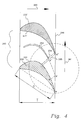
- the arrangement shown in FIG. 1 shows a hole-shaped flow channel 120 in the front view.
- the flow channel 120 has an inner (hub side) flow-limiting side wall 122 and an outer (housing side) flow-limiting side wall 123.
- two are in the Flow channels 120 arranged full blades 130, 130 'shown.
- the full shovels 130, 130 ' are aligned radially, with the extended central axes 124 of the Full blades 130, 130 'at the center 121 or near the center 121 of the Cut flow channel 120.
- the full blades 130, 130 ' have a height H on.
- the full blades 130, 130 'arranged in the flow channel limit one Blade channel 160.
- the blade channel 160 shown in FIG. 1 corresponds here to one Blade channel of a flow grid of an axially flowed through turbomachine.
- both on the hub side and on the housing side flow-limiting side wall 122, 123 each have an intermediate blade 150, 155 arranged.
- the intermediate blades 150, 155 are radially aligned in the same way as the full blades 130, 130 '.
- the intermediate blades 150, 155 are of a smaller size Height h as the full blades.
- the height h of the intermediate blades 150, 155 in Figure 1 corresponds to about 10% of the height H of the full blades 130, 130 '.
- the Intermediate blades 150, 155 could also be designed with different heights. It turned out that with a view to an optimal reduction of the Flow losses the height h of the intermediate blade is an important influencing variable.
- the blade channel 160 becomes dependent on the arrangement of the intermediate blades 150, 155 each locally divided into two subchannels 170, 171 and 180, 181.
- the corners of the subchannels between the intermediate blade and the side wall in the longitudinal direction of the subchannels executed at right angles in the embodiment according to FIG.
- FIG. 2 shows a top view of a section through a blade channel 60, which is part of the prior art.
- the blade channel 60 is shown in simplified form as a section of a grating developed in the plane.
- the circumferential direction of the grating arranged on the circumference of a machine thus corresponds to the longitudinal direction 91 of the grating in the illustration.
- the blade channel 60 is delimited in the longitudinal direction 91 of the grid by the full blades 30 and 30 '.
- the full blades 30, 30 ' are geometrically identical here.
- the axial chord length T of the solid blades 30, 30 'and the chord length s of the solid blades 30, 30' are shown as the geometric sizes of the solid blades 30, 30 '.
- the respective profile thickness results from fitting circles into the profile contour of the blade.
- the maximum profile thickness thus represents the diameter of the largest circle that fits the profile contour.
- the maximum profile thickness of the full blades 30, 30 ' is marked with d.
- the blade thickness ratio d / s and the blade height ratio H / s can be defined on the basis of the geometric size definitions of the full blades 30, 30 ′ listed above.
- the narrowest cross section 65 of the blade channel 60 is characterized by the distance between A and B ".
- the grid shown in Figure 2 is designed here as a turbine grid.
- the scoop channel 60 consequently exhibits a continuous narrowing of the channel cross-section from the entrance to the exit of the blade channel 60.
- the blade channel 60 is flowed against by fluid in accordance with the flow direction 12.
- the Fluid enters the blade channel 60 and here follows the blade profile redirected.
- This flow following the blade profile is called the primary flow 10 designated.
- This Pressure gradient within the blade channel 60 leads to the formation of a Secondary flow 11 mainly in the sidewall boundary layer. Based on these Secondary flow 11 also leads to the fusing of the channel vortex 11 '.
- corner vertebrae 11 "occur along the corners of the blade channel. This as Secondary flows designated flow forms 11, 11 ', 11' 'lead to high Loss of fluid flow through the blade channel.
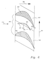
- FIG. 3 shows a blade channel 160 in the same sectional view as in FIG. 2, in which an intermediate blade 150 is arranged according to the invention.
- the inflow 112 the grid is shown from the left.
- an intermediate blade 150 is approximately centered in the blade channel 160 arranged.
- the blade channel 160 divided into two sub-channels 180, 181. It was found that the losses in the Flow through the blade channel in the sum of the losses of the sub-channels 180, 181 Arrangement of the intermediate blade 150 in the blade channel 160 opposite the Arrangement without an intermediate blade can be significantly reduced.
- the blade nose 153 of the intermediate blade 150 is in this embodiment of the invention set back by an axial distance V.
- the setback of the blade nose 153 the intermediate blade 150 relates to the straight line connecting the blade lugs 133, 133 'of the full blades 130, 130', i.e. the front line 195 of the grille.
- the Reset V is here in a particularly preferred embodiment of the invention about 5% of the axial chord length T of the full blades 130, 130 '.
- the intermediate blade 150 in FIG. 3 has a small maximum profile thickness d ' Intermediate blade 150 executed.
- This maximum professional thickness d ' corresponds here to about 10% the maximum profile thickness d of the full blades 130, 130 '.
- the suction side 152 of the intermediate blade 150 in the exemplary embodiment Execution of the invention has approximately the same profile contour profile as that Suction side 132 of the full blade 130.
- the profile contours are assigned here via the axial position in the blade channel 160.
- the radius of curvature R 'on the suction side the intermediate blade 150 here the radius of curvature R of the full blade on the suction side 130 in the area after the narrowest cross section (A'B ') of the subchannel between the Full blade 130 and the intermediate blade 150.
- the intermediate blade 150 in FIG. 3 is in the blade channel 160 between the Full blades 130, 130 ′ are arranged such that the rear edge 154 of the intermediate blade 150 to be in alignment with the trailing edges B and B "of the full blades 130, 130 ' is coming.
- the fluid flow is thus in the area of the subchannel 180 between A "and B ' guided on both sides.
- the aerodynamic load of the Full bucket diminishes as well as the point of highest aerodynamic Load of the blade profile in the blade channel 160 is shifted downstream. Farther there is a reduction in secondary flow losses and beyond an increase in the deflection of the primary flow in the vane duct 160.
- the trailing edge 254 is advantageously offset upstream of the narrowest cross section (AB ") of the blade channel 260.
- the narrowest cross section (AB") of the blade channel 260 is thereby not reduced.
- the area of the rear edge 254 of the intermediate blade 250 is shown enlarged in FIG.
- the offset q x of the rear edge 254 here is approximately 110% of the distance q 1 .
- the distance q 1 is defined as the distance between the non-offset rear edge B 'of the intermediate blade 250, which is arranged in alignment with the rear edges B and B "of the full blades, and the narrowest cross section (AB") of the blade channel.
- Both the distance q 1 and q x are to be measured perpendicular to the narrowest cross-section (AB ") of the blade channel.
- To determine the distance use the auxiliary line labeled ⁇ through point B ', which is parallel to the narrowest cross-section (AB") is registered.
- the intermediate blade in one piece with the side wall. This can be realized, for example, by casting or machining.
- the Side walls of the bladed flow channels in turbomachinery often arise by lining up rhombic platforms. These platforms are often made in one piece with the full blades.
- Figure 6 shows such an arrangement two platforms 326 and 327.
- the platforms 326, 327 lined up here form a side wall of the blade channel 360.
- the parting line 328 between the platforms In the embodiment shown in FIG. 6, 326 and 327 is centered in the blade channel 360 arranged.
- the intermediate blade 350 is also approximately in the middle here Blade channel 360 positioned.
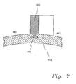
- Figure 7 shows an embodiment of the invention, in which the intermediate blade 450 in a T-groove 499 is arranged on the side wall 422.
- This arrangement is especially then useful if the flow-limiting side wall and the intermediate blade as separate parts were manufactured.
Priority Applications (1)
| Application Number | Priority Date | Filing Date | Title |
|---|---|---|---|
| EP98810756A EP0978632A1 (fr) | 1998-08-07 | 1998-08-07 | Turbomachine avec aubes intermédiaires divisant le courant |
Applications Claiming Priority (1)
| Application Number | Priority Date | Filing Date | Title |
|---|---|---|---|
| EP98810756A EP0978632A1 (fr) | 1998-08-07 | 1998-08-07 | Turbomachine avec aubes intermédiaires divisant le courant |
Publications (1)
| Publication Number | Publication Date |
|---|---|
| EP0978632A1 true EP0978632A1 (fr) | 2000-02-09 |
Family
ID=8236235
Family Applications (1)
| Application Number | Title | Priority Date | Filing Date |
|---|---|---|---|
| EP98810756A Withdrawn EP0978632A1 (fr) | 1998-08-07 | 1998-08-07 | Turbomachine avec aubes intermédiaires divisant le courant |
Country Status (1)
| Country | Link |
|---|---|
| EP (1) | EP0978632A1 (fr) |
Cited By (18)
| Publication number | Priority date | Publication date | Assignee | Title |
|---|---|---|---|---|
| EP1424467A2 (fr) * | 2002-11-27 | 2004-06-02 | General Electric Company | Rangée de cordes longues et courtes d'aubes de turbine |
| FR2907519A1 (fr) * | 2006-10-20 | 2008-04-25 | Snecma Sa | Nageoire de plateforme de soufflante |
| EP1927723A1 (fr) | 2006-11-28 | 2008-06-04 | Deutsches Zentrum für Luft- und Raumfahrt e.V. | Palier de stator d'un compresseur axial d'une turbomachine avec lamelles transversales pour l'augmentation de rendement |
| EP2194232A2 (fr) | 2008-12-04 | 2010-06-09 | Rolls-Royce Deutschland Ltd & Co KG | Turbomachine dotée d'une barrière à couche frontière sur la paroi latérale |
| FR2939852A1 (fr) * | 2008-12-15 | 2010-06-18 | Snecma | Etage d'aubes statoriques dans un compresseur |
| EP2740897A1 (fr) * | 2012-01-04 | 2014-06-11 | General Electric Company | Diffuseur de turbine |
| JP2014163367A (ja) * | 2013-02-28 | 2014-09-08 | Hitachi Ltd | 軸流タービンの動翼列、および軸流タービン |
| FR3014943A1 (fr) * | 2013-12-18 | 2015-06-19 | Snecma | Piece de turbomachine a surface non-axisymetrique |
| EP3040512A1 (fr) * | 2014-12-29 | 2016-07-06 | General Electric Company | Dispositif de compresseur et compresseur associé |
| RU170008U1 (ru) * | 2016-06-27 | 2017-04-11 | федеральное государственное бюджетное образовательное учреждение высшего образования "Ивановский государственный энергетический университет имени В.И. Ленина" (ИГЭУ) | Лопаточная решетка осевой турбомашины |
| US20180017019A1 (en) * | 2016-07-15 | 2018-01-18 | General Electric Company | Turbofan engine wth a splittered rotor fan |
| US9938984B2 (en) | 2014-12-29 | 2018-04-10 | General Electric Company | Axial compressor rotor incorporating non-axisymmetric hub flowpath and splittered blades |
| US20180156124A1 (en) * | 2016-12-01 | 2018-06-07 | General Electric Company | Turbine engine frame incorporating splitters |
| EP3372785A1 (fr) * | 2017-03-09 | 2018-09-12 | General Electric Company | Ensemble d'aubes de turbine incorporant des séparateurs |
| FR3068385A1 (fr) * | 2017-06-28 | 2019-01-04 | Safran Aircraft Engines | Ailette amovible pour un element annulaire aubage de turbomachine |
| DE102019200885A1 (de) * | 2019-01-24 | 2020-07-30 | MTU Aero Engines AG | Leitgitter für eine Strömungsmaschine |
| IT202100002240A1 (it) * | 2021-02-02 | 2022-08-02 | Gen Electric | Motore a turbine con palette a flusso trasversale ridotto |
| WO2023021258A1 (fr) * | 2021-08-20 | 2023-02-23 | Safran | Pièce statorique d'une turbomachine comprenant une pale et une ailette définissant entre elles une surface décroissante d'amont en aval selon le sens d'écoulement des gaz |
Citations (5)
| Publication number | Priority date | Publication date | Assignee | Title |
|---|---|---|---|---|
| US2920864A (en) * | 1956-05-14 | 1960-01-12 | United Aircraft Corp | Secondary flow reducer |
| US3039736A (en) * | 1954-08-30 | 1962-06-19 | Pon Lemuel | Secondary flow control in fluid deflecting passages |
| DE2135286A1 (de) * | 1971-07-15 | 1973-01-25 | Wilhelm Prof Dr Ing Dettmering | Lauf- und leitradgitter fuer turbomaschinen |
| US3837761A (en) * | 1971-08-20 | 1974-09-24 | Westinghouse Electric Corp | Guide vanes for supersonic turbine blades |
| FR2432608A1 (fr) * | 1978-07-31 | 1980-02-29 | Alsthom Atlantique | Grille d'aubes pour turbine ou compresseur |
-
1998
- 1998-08-07 EP EP98810756A patent/EP0978632A1/fr not_active Withdrawn
Patent Citations (5)
| Publication number | Priority date | Publication date | Assignee | Title |
|---|---|---|---|---|
| US3039736A (en) * | 1954-08-30 | 1962-06-19 | Pon Lemuel | Secondary flow control in fluid deflecting passages |
| US2920864A (en) * | 1956-05-14 | 1960-01-12 | United Aircraft Corp | Secondary flow reducer |
| DE2135286A1 (de) * | 1971-07-15 | 1973-01-25 | Wilhelm Prof Dr Ing Dettmering | Lauf- und leitradgitter fuer turbomaschinen |
| US3837761A (en) * | 1971-08-20 | 1974-09-24 | Westinghouse Electric Corp | Guide vanes for supersonic turbine blades |
| FR2432608A1 (fr) * | 1978-07-31 | 1980-02-29 | Alsthom Atlantique | Grille d'aubes pour turbine ou compresseur |
Cited By (32)
| Publication number | Priority date | Publication date | Assignee | Title |
|---|---|---|---|---|
| EP1424467A3 (fr) * | 2002-11-27 | 2006-09-27 | General Electric Company | Rangée de cordes longues et courtes d'aubes de turbine |
| EP1424467A2 (fr) * | 2002-11-27 | 2004-06-02 | General Electric Company | Rangée de cordes longues et courtes d'aubes de turbine |
| RU2456458C2 (ru) * | 2006-10-20 | 2012-07-20 | Снекма | Площадка компрессора газотурбинного двигателя, компрессор газотурбинного двигателя и газотурбинный двигатель |
| FR2907519A1 (fr) * | 2006-10-20 | 2008-04-25 | Snecma Sa | Nageoire de plateforme de soufflante |
| EP1916385A1 (fr) * | 2006-10-20 | 2008-04-30 | Snecma | Nageoire de plateforme de soufflante |
| US8303258B2 (en) | 2006-10-20 | 2012-11-06 | Snecma | Fan platform fin |
| EP1927723A1 (fr) | 2006-11-28 | 2008-06-04 | Deutsches Zentrum für Luft- und Raumfahrt e.V. | Palier de stator d'un compresseur axial d'une turbomachine avec lamelles transversales pour l'augmentation de rendement |
| DE102006057063B3 (de) * | 2006-11-28 | 2008-07-31 | Deutsches Zentrum für Luft- und Raumfahrt e.V. | Stator-Stufe eines Axialverdichters einer Strömungsmaschine mit Querlamellen zur Wirkungsgradsteigerung |
| EP2194232A2 (fr) | 2008-12-04 | 2010-06-09 | Rolls-Royce Deutschland Ltd & Co KG | Turbomachine dotée d'une barrière à couche frontière sur la paroi latérale |
| EP2194232A3 (fr) * | 2008-12-04 | 2013-05-15 | Rolls-Royce Deutschland Ltd & Co KG | Turbomachine dotée d'une barrière à couche frontière sur la paroi latérale |
| US8591176B2 (en) | 2008-12-04 | 2013-11-26 | Rolls-Royce Deutschland Ltd & Co Kg | Fluid flow machine with sidewall boundary layer barrier |
| FR2939852A1 (fr) * | 2008-12-15 | 2010-06-18 | Snecma | Etage d'aubes statoriques dans un compresseur |
| EP2740897A1 (fr) * | 2012-01-04 | 2014-06-11 | General Electric Company | Diffuseur de turbine |
| JP2014163367A (ja) * | 2013-02-28 | 2014-09-08 | Hitachi Ltd | 軸流タービンの動翼列、および軸流タービン |
| FR3014943A1 (fr) * | 2013-12-18 | 2015-06-19 | Snecma | Piece de turbomachine a surface non-axisymetrique |
| US10519980B2 (en) | 2013-12-18 | 2019-12-31 | Safran Aircraft Engines | Turbomachine component or collection of components and associated turbomachine |
| EP3040512A1 (fr) * | 2014-12-29 | 2016-07-06 | General Electric Company | Dispositif de compresseur et compresseur associé |
| US9938984B2 (en) | 2014-12-29 | 2018-04-10 | General Electric Company | Axial compressor rotor incorporating non-axisymmetric hub flowpath and splittered blades |
| US9874221B2 (en) | 2014-12-29 | 2018-01-23 | General Electric Company | Axial compressor rotor incorporating splitter blades |
| RU170008U1 (ru) * | 2016-06-27 | 2017-04-11 | федеральное государственное бюджетное образовательное учреждение высшего образования "Ивановский государственный энергетический университет имени В.И. Ленина" (ИГЭУ) | Лопаточная решетка осевой турбомашины |
| US20180017019A1 (en) * | 2016-07-15 | 2018-01-18 | General Electric Company | Turbofan engine wth a splittered rotor fan |
| US20180156124A1 (en) * | 2016-12-01 | 2018-06-07 | General Electric Company | Turbine engine frame incorporating splitters |
| EP3372785A1 (fr) * | 2017-03-09 | 2018-09-12 | General Electric Company | Ensemble d'aubes de turbine incorporant des séparateurs |
| WO2018162485A1 (fr) * | 2017-03-09 | 2018-09-13 | General Electric Company | Agencement de profils aérodynamiques de turbine incorporant des séparateurs |
| CN110366631A (zh) * | 2017-03-09 | 2019-10-22 | 通用电气公司 | 包含分流器的涡轮翼型件布置 |
| FR3068385A1 (fr) * | 2017-06-28 | 2019-01-04 | Safran Aircraft Engines | Ailette amovible pour un element annulaire aubage de turbomachine |
| DE102019200885A1 (de) * | 2019-01-24 | 2020-07-30 | MTU Aero Engines AG | Leitgitter für eine Strömungsmaschine |
| US11280212B2 (en) | 2019-01-24 | 2022-03-22 | MTU Aero Engines AG | Guide vane cascade for a turbomachine |
| IT202100002240A1 (it) * | 2021-02-02 | 2022-08-02 | Gen Electric | Motore a turbine con palette a flusso trasversale ridotto |
| US11959393B2 (en) | 2021-02-02 | 2024-04-16 | General Electric Company | Turbine engine with reduced cross flow airfoils |
| WO2023021258A1 (fr) * | 2021-08-20 | 2023-02-23 | Safran | Pièce statorique d'une turbomachine comprenant une pale et une ailette définissant entre elles une surface décroissante d'amont en aval selon le sens d'écoulement des gaz |
| FR3126236A1 (fr) * | 2021-08-20 | 2023-02-24 | Safran | Pièce statorique d’une turbomachine comprenant une pale et une ailette définissant entre elles une surface décroissante d’amont en aval selon le sens d’écoulement des gaz. |
Similar Documents
| Publication | Publication Date | Title |
|---|---|---|
| EP0978632A1 (fr) | Turbomachine avec aubes intermédiaires divisant le courant | |
| EP2473743B1 (fr) | Aube mobile de compresseur pour un compresseur axial | |
| EP0972128B1 (fr) | Structure superficielle pour la paroi d'un canal d'ecoulement ou d'une aube de turbine | |
| DE69921320T2 (de) | Turbinenstatorschaufel | |
| EP2194232B1 (fr) | Turbomachine dotée d'une barrière à couche frontière sur la paroi latérale | |
| EP0799973B1 (fr) | Contour de paroi pour une turbomachine axiale | |
| DE1628237C3 (de) | Stromungsmaschinen Umlenk schaufel gitter | |
| DE3940607A1 (de) | Labyrinth-dichtungssystem | |
| DE2841616A1 (de) | Schaufelgitter fuer eine axialstroemungsmaschine | |
| EP1113145A1 (fr) | Aube pour turbine a gaz avec section de mesure sur le bord de fuite | |
| DE2241194A1 (de) | Stroemungsmaschinenschaufel mit tragfluegelfoermigem querschnittsprofil und mit einer vielzahl von in schaufellaengsrichtung verlaufenden kuehlkanaelen | |
| CH697806A2 (de) | Turbinenschaufel-Deckbandkantenprofil. | |
| DE102008037154A1 (de) | Strömungsarbeitsmaschine | |
| WO2007003614A1 (fr) | Aubes de turbomachine | |
| EP2913478B1 (fr) | Aubes en tandem d'une turbomachine | |
| EP3176370A1 (fr) | Ensemble d'aubes directrices pour turbomachine | |
| WO2011029420A1 (fr) | Dispositif de déflexion pour un écoulement de fuite dans une turbine à gaz et turbine à gaz correspondante | |
| EP3404210A1 (fr) | Segment de grille d'aubes d'une turbomachine avec paroi de plateforme non-axisymétrique , grille d'aubes, canal d'aube, plateforme, turbomachine associés | |
| EP0798447B1 (fr) | Aube pour une turbomachine | |
| DE102012104240B4 (de) | Hybridströmungs-Schaufeldesigns | |
| EP2913479B1 (fr) | Aubes en tandem d'une turbomachine | |
| EP1012445A1 (fr) | Aube pour une turbomachine, et turbine a vapeur | |
| EP1167689A1 (fr) | Configuration d'une aube de turbine refroidissable | |
| EP3401504A1 (fr) | Grille d'aube | |
| EP2410131A2 (fr) | Rotor d'une turbomachine |
Legal Events
| Date | Code | Title | Description |
|---|---|---|---|
| PUAI | Public reference made under article 153(3) epc to a published international application that has entered the european phase |
Free format text: ORIGINAL CODE: 0009012 |
|
| AK | Designated contracting states |
Kind code of ref document: A1 Designated state(s): AT BE CH CY DE DK ES FI FR GB GR IE IT LI LU MC NL PT SE |
|
| AX | Request for extension of the european patent |
Free format text: AL;LT;LV;MK;RO;SI |
|
| AKX | Designation fees paid | ||
| STAA | Information on the status of an ep patent application or granted ep patent |
Free format text: STATUS: THE APPLICATION IS DEEMED TO BE WITHDRAWN |
|
| 18D | Application deemed to be withdrawn |
Effective date: 20000810 |
|
| REG | Reference to a national code |
Ref country code: DE Ref legal event code: 8566 |