EP0977976B1 - Wärmemengenmesser für fluide strömungen und verfahren zur bestimmung der wärmemenge - Google Patents
Wärmemengenmesser für fluide strömungen und verfahren zur bestimmung der wärmemenge Download PDFInfo
- Publication number
- EP0977976B1 EP0977976B1 EP98931983A EP98931983A EP0977976B1 EP 0977976 B1 EP0977976 B1 EP 0977976B1 EP 98931983 A EP98931983 A EP 98931983A EP 98931983 A EP98931983 A EP 98931983A EP 0977976 B1 EP0977976 B1 EP 0977976B1
- Authority
- EP
- European Patent Office
- Prior art keywords
- temperature
- heat
- operating time
- determination
- volume flow
- Prior art date
- Legal status (The legal status is an assumption and is not a legal conclusion. Google has not performed a legal analysis and makes no representation as to the accuracy of the status listed.)
- Expired - Lifetime
Links
- 238000000034 method Methods 0.000 title claims abstract description 24
- 238000012544 monitoring process Methods 0.000 title claims abstract description 4
- 239000012530 fluid Substances 0.000 title claims description 7
- 238000009434 installation Methods 0.000 claims abstract 3
- 238000012546 transfer Methods 0.000 claims description 13
- 230000001419 dependent effect Effects 0.000 claims description 4
- 238000001514 detection method Methods 0.000 claims description 3
- 239000013529 heat transfer fluid Substances 0.000 claims description 3
- 230000002596 correlated effect Effects 0.000 claims description 2
- 239000000523 sample Substances 0.000 claims 9
- 230000015572 biosynthetic process Effects 0.000 claims 2
- 230000001174 ascending effect Effects 0.000 claims 1
- 238000006073 displacement reaction Methods 0.000 claims 1
- 239000000203 mixture Substances 0.000 claims 1
- 230000032258 transport Effects 0.000 claims 1
- 238000009826 distribution Methods 0.000 description 5
- 238000005259 measurement Methods 0.000 description 5
- 238000012937 correction Methods 0.000 description 2
- 230000000875 corresponding effect Effects 0.000 description 2
- 238000004519 manufacturing process Methods 0.000 description 2
- 239000002918 waste heat Substances 0.000 description 2
- 230000000712 assembly Effects 0.000 description 1
- 238000000429 assembly Methods 0.000 description 1
- 230000005540 biological transmission Effects 0.000 description 1
- 238000009529 body temperature measurement Methods 0.000 description 1
- 238000011161 development Methods 0.000 description 1
- 230000018109 developmental process Effects 0.000 description 1
- 238000005338 heat storage Methods 0.000 description 1
- 238000005086 pumping Methods 0.000 description 1
- 230000005855 radiation Effects 0.000 description 1
- 230000009897 systematic effect Effects 0.000 description 1
Images

Classifications
-
- G—PHYSICS
- G01—MEASURING; TESTING
- G01K—MEASURING TEMPERATURE; MEASURING QUANTITY OF HEAT; THERMALLY-SENSITIVE ELEMENTS NOT OTHERWISE PROVIDED FOR
- G01K17/00—Measuring quantity of heat
- G01K17/06—Measuring quantity of heat conveyed by flowing media, e.g. in heating systems e.g. the quantity of heat in a transporting medium, delivered to or consumed in an expenditure device
- G01K17/08—Measuring quantity of heat conveyed by flowing media, e.g. in heating systems e.g. the quantity of heat in a transporting medium, delivered to or consumed in an expenditure device based upon measurement of temperature difference or of a temperature
- G01K17/10—Measuring quantity of heat conveyed by flowing media, e.g. in heating systems e.g. the quantity of heat in a transporting medium, delivered to or consumed in an expenditure device based upon measurement of temperature difference or of a temperature between an inlet and an outlet point, combined with measurement of rate of flow of the medium if such, by integration during a certain time-interval
- G01K17/12—Indicating product of flow and temperature difference directly or temperature
- G01K17/16—Indicating product of flow and temperature difference directly or temperature using electrical or magnetic means for both measurements
-
- F—MECHANICAL ENGINEERING; LIGHTING; HEATING; WEAPONS; BLASTING
- F24—HEATING; RANGES; VENTILATING
- F24S—SOLAR HEAT COLLECTORS; SOLAR HEAT SYSTEMS
- F24S40/00—Safety or protection arrangements of solar heat collectors; Preventing malfunction of solar heat collectors
- F24S40/90—Arrangements for testing solar heat collectors
-
- G—PHYSICS
- G01—MEASURING; TESTING
- G01K—MEASURING TEMPERATURE; MEASURING QUANTITY OF HEAT; THERMALLY-SENSITIVE ELEMENTS NOT OTHERWISE PROVIDED FOR
- G01K17/00—Measuring quantity of heat
- G01K17/06—Measuring quantity of heat conveyed by flowing media, e.g. in heating systems e.g. the quantity of heat in a transporting medium, delivered to or consumed in an expenditure device
-
- G—PHYSICS
- G01—MEASURING; TESTING
- G01K—MEASURING TEMPERATURE; MEASURING QUANTITY OF HEAT; THERMALLY-SENSITIVE ELEMENTS NOT OTHERWISE PROVIDED FOR
- G01K17/00—Measuring quantity of heat
- G01K17/06—Measuring quantity of heat conveyed by flowing media, e.g. in heating systems e.g. the quantity of heat in a transporting medium, delivered to or consumed in an expenditure device
- G01K17/08—Measuring quantity of heat conveyed by flowing media, e.g. in heating systems e.g. the quantity of heat in a transporting medium, delivered to or consumed in an expenditure device based upon measurement of temperature difference or of a temperature
- G01K17/10—Measuring quantity of heat conveyed by flowing media, e.g. in heating systems e.g. the quantity of heat in a transporting medium, delivered to or consumed in an expenditure device based upon measurement of temperature difference or of a temperature between an inlet and an outlet point, combined with measurement of rate of flow of the medium if such, by integration during a certain time-interval
-
- Y—GENERAL TAGGING OF NEW TECHNOLOGICAL DEVELOPMENTS; GENERAL TAGGING OF CROSS-SECTIONAL TECHNOLOGIES SPANNING OVER SEVERAL SECTIONS OF THE IPC; TECHNICAL SUBJECTS COVERED BY FORMER USPC CROSS-REFERENCE ART COLLECTIONS [XRACs] AND DIGESTS
- Y02—TECHNOLOGIES OR APPLICATIONS FOR MITIGATION OR ADAPTATION AGAINST CLIMATE CHANGE
- Y02B—CLIMATE CHANGE MITIGATION TECHNOLOGIES RELATED TO BUILDINGS, e.g. HOUSING, HOUSE APPLIANCES OR RELATED END-USER APPLICATIONS
- Y02B10/00—Integration of renewable energy sources in buildings
- Y02B10/20—Solar thermal
-
- Y—GENERAL TAGGING OF NEW TECHNOLOGICAL DEVELOPMENTS; GENERAL TAGGING OF CROSS-SECTIONAL TECHNOLOGIES SPANNING OVER SEVERAL SECTIONS OF THE IPC; TECHNICAL SUBJECTS COVERED BY FORMER USPC CROSS-REFERENCE ART COLLECTIONS [XRACs] AND DIGESTS
- Y02—TECHNOLOGIES OR APPLICATIONS FOR MITIGATION OR ADAPTATION AGAINST CLIMATE CHANGE
- Y02B—CLIMATE CHANGE MITIGATION TECHNOLOGIES RELATED TO BUILDINGS, e.g. HOUSING, HOUSE APPLIANCES OR RELATED END-USER APPLICATIONS
- Y02B10/00—Integration of renewable energy sources in buildings
- Y02B10/70—Hybrid systems, e.g. uninterruptible or back-up power supplies integrating renewable energies
-
- Y—GENERAL TAGGING OF NEW TECHNOLOGICAL DEVELOPMENTS; GENERAL TAGGING OF CROSS-SECTIONAL TECHNOLOGIES SPANNING OVER SEVERAL SECTIONS OF THE IPC; TECHNICAL SUBJECTS COVERED BY FORMER USPC CROSS-REFERENCE ART COLLECTIONS [XRACs] AND DIGESTS
- Y02—TECHNOLOGIES OR APPLICATIONS FOR MITIGATION OR ADAPTATION AGAINST CLIMATE CHANGE
- Y02E—REDUCTION OF GREENHOUSE GAS [GHG] EMISSIONS, RELATED TO ENERGY GENERATION, TRANSMISSION OR DISTRIBUTION
- Y02E10/00—Energy generation through renewable energy sources
- Y02E10/40—Solar thermal energy, e.g. solar towers
Definitions
- the invention is based on a method of the generic type of the main claim. Usually those are flowing in Fluids conveyed or fed to a heat exchanger or the amount of heat withdrawn as a finite sum of Products of a volume flow and a temperature difference, weighted with the specific heat capacity of the fluid educated.
- this volume flow is included Measured with the help of a volume flow sensor, this Volume flow converted into pulses per unit volume (calibrated). These pulses are fed to a device which this volume flow one measured in the fluid Assigns temperature and from it the funded, absolute Amount of heat or that supplied to a heat exchanger or the amount of heat removed. These amounts of heat are added over a period of time.
- the U.S. patents US 4,224,825 and US 4,332,164 show such devices, where volume flow sensors built into the fluid line are used, which represent the volume flow Give impulses.
- a disadvantage of this method is the systematic error of the Heat quantity measurement in systems with essentially discontinuous volume flow and consequently inhomogeneous Temperature distribution in the same.
- the temperature measurement takes place according to the known method in different The temperature ranges of the volume flow are different Line sections can be assigned.
- temperature detection is for discontinuous operation randomly distributed to the conveyor; d. H. in dependence of the phase position and resolution of the pulse generator Volumetric flow encoder fall at the start of a measurement different number of cycles in a temperature range; it there is an undefined deviation of the measured Value of the actual value (integral).
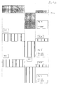
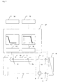
- FIG. 1 shows a structure of a system and FIG.
- a pumping time t pump is entered on the x-axis and a differential temperature T 3; 4 - T 4; 5 is entered on the y-axis, which is a temperature difference between the temperatures at the heat exchanger inlet and the heat exchanger outlet, the reference value being the Temperature T 4; 5 is selected at the heat exchanger outlet. Temperature deviations upwards and downwards are shown.
- 1b) and 1c) illustrate that it depends on the resolution of the pulse generator of the volume flow transmitter (corresponding to the distance ⁇ of the pulses symbolized by vertical black lines) and the phase position of the pulses at the start of the measurement (corresponding to the distance of the first pulse deviations ( ⁇ ) of the measured value ( ⁇ ) from the actual value (integral, ⁇ ) can occur.
- the invention has for its object a generic To create procedures that are cost effective and high Accuracy in determining the volume flow enables.
- the volume flow is as Function of the pump runtime determined via sensors that the Running time of a temperature edge within a line determine.
- the temperature of the heat transfer medium Energy source (energy collector) is one certain value increased over the temperature of the measuring section.
- the temperature edge (or its turning point) reaches the given by a temperature sensor 11 front Measuring point of the measuring section, the running time counter becomes the Conveyor set to zero and begins to count. In fixed time periods are simultaneously used to record the Heat quantity necessary parameters recorded and saved.
- the temperature edge (or its turning point) reaches the given by a temperature sensor 12 rear measuring point the measuring section, the running time of the conveyor saved.
- This runtime becomes the volume of the measuring section assigned.
- the Volume flow as a function of the pump runtime in any Intervals are shown and assigned to the recorded parameters (calibrated). The iteration with an infinite number Iteration steps result in the integral to be displayed.
- the method becomes a trained to deliver impulses Volume flow encoder used and it is the measuring section as that between two pulses of the volume flow sensor Volume shown.
- the first time counter of the conveyor is set to zero when the conveyor is switched on and begins to count. In fixed time periods the parameters necessary to record the amount of heat recorded and saved.
- the second time counter of the Conveyor is at the first pulse of the encoder of the volume encoder is also set to zero and begins counting.
- the second impulse of the generator of the The volume flow encoder holds the second time counter Conveyor.
- the running time of the pump between the first and second pulse of the pulse generator Volume flow sensor (time measurement second time counter) is the Assigned the nominal volume per pulse of the volume flow encoder.
- the measured delivery volume (dV / dt m ) is multiplied by a temperature-dependent correction factor in order to determine the real delivery volume (dV / dt e ).
- a Device for performing the method can determined amount of heat to check the function of a thermal solar system can be used by the certain energy supplied to a heat consumer the energy compared to the heat consumer due to the internal energy of the energy collector and the Connection lines, as well as the heat exchanger per Charge cycle must be fed.
- the device for performing the method is the energy source a radiation collector, a heat exchanger, heat pipes, one Waste heat source or an exogenous production process; the Energy sink a heat consumer, a heat store or an endogenous production process.
- a heat generator 1 is shown, the Connection lines 2; 3 and a measuring section located therein 10 and connecting lines 5; 6 with a Heat consumer 7; 8 is connected.
- the in the heat generator 1 heated heat transfer medium is conveyed by the conveyor 9 the connecting line 2 with the measuring section 10 contained therein and the connecting line 3 in the in the heat accumulator 7 located heat exchanger 4 promoted. There he exchanges heat and returns via the connecting lines 5 and 6 to Heat generator back, provided there is sufficient waste heat, to be warmed up again.
- Figure 1a shows the course of the temperature difference T 3; 4 - T 4; 5 as a function of the pump running time.
- the time t pump shown in the abscissa is proportional to the volume of the heat carrier in lines 3 and 2 and to the volume of the heat carrier in the heat generator 1.
- the representation of the differential temperature of the heat exchanger input minus the heat exchanger output takes place for the first approximation constant temperature T 4; 5 at the heat exchanger output as a reference.
- the integral over the edge curve corresponds to the amount of heat supplied to the heat exchanger.
- FIG. 1b shows the distribution of the pulses of a volume flow transmitter with finite resolution with the starting time t 1, shown over the same time axis t pump .
- the heat quantity is formed according to this method by forming the finite sum of products from the temperature difference and partial volume, weighted with the specific heat capacity of the transmission medium.
- FIG. 1c shows FIG. 1b with a different starting time t 2 .
- FIG. 2 shows the device for forming the volume flow as a function of the pump running time, ie for calibrating the heat meter. After reaching a temperature T 1 of the heat generator 1 which is substantially higher than the temperature of the line section 2 and the measuring device 10 contained therein; turns on the pump 9. The time counters 15 and 16 are set to zero and begin to count.
- the temperature flank of the heat transfer fluid and, in particular, its variables that characterize the course, such as, for example, the slope or the turning tangent, are pumped from the heat generator 1 into the line 2 and reach the temperature sensor 11 after an indefinite time t to the arithmetic unit. After a certain time T m , this characteristic quantity of the temperature flank reaches the temperature sensor 12.
- the time counter 16 is stopped and passes the stored time on to the arithmetic unit. This calculates the volume flow as a function of the pump running time from the measured times and the volume of the measuring section entered via a control panel. The calibration of the heat meter is now complete.
- the pump runtime When the system is operating, the pump runtime is increased by one determined another time counter and from it according to the above. method the amount of heat conveyed is calculated in the calculator and output on a display panel. According to the invention electronic iteration the pump runtime in arbitrarily small Subdivide intervals and with the measured Temperature differences and the specific heat capacity to calculate the integral heat quantity of the medium.
Landscapes
- Engineering & Computer Science (AREA)
- Chemical & Material Sciences (AREA)
- Physics & Mathematics (AREA)
- Combustion & Propulsion (AREA)
- General Physics & Mathematics (AREA)
- Sustainable Development (AREA)
- Thermal Sciences (AREA)
- Sustainable Energy (AREA)
- Mechanical Engineering (AREA)
- General Engineering & Computer Science (AREA)
- Life Sciences & Earth Sciences (AREA)
- Investigating Or Analyzing Materials Using Thermal Means (AREA)
- Measuring Temperature Or Quantity Of Heat (AREA)
- Indicating Or Recording The Presence, Absence, Or Direction Of Movement (AREA)
- Pipeline Systems (AREA)
Description
- mit geringem Kostenaufwand erfolgen kann
- ohne mechanisch bewegte Baugruppen erfolgen kann
- mit unendlich hoher Auflösung erfolgen kann.
- Fig. 1:
- eine Darstellung des Systems zur Funktionsüberwachung und Wärmemengenerfassung einer thermischen Solaranlage
- Fig. 1a
- eine inhomogene Temperaturverteilung, wie sie sich als Folge eines diskontinuierliches Betriebes ergeben kann, wobei der Verlauf einer Temperaturdifferenz T3;4 - T4;5 als Funktion einer Pumpenlaufzeit tpump dargestellt ist. Die Temperatur T4;5 ist die in erster Näherung konstante Bezugstemperatur (Abszisse).
- Fig. 1b
- eine Verteilung von Impulsen (senkrechte Striche) eines Volumenstromgebers mit endlicher Auflösung mit dem Startzeitpunkt t1
- Fig. 1 c
- eine Verteilung gemäß Figur 1 b mit einem anderen Startzeitpunkt t2.
- 1
- Energiesammler
- 2;3
- Verbindungsleitung zwischen Ausgang des Energie sammlers und den Eingang des Wärmetauschers
- 4
- Wärmetauscher
- 5;6
- Verbindungsleitung zwischen Ausgang des Wärmetauschers und Eingang des Energiesammlers
- 7
- Wärmespeicher
- 8
- Gebäude
- 9
- Fördereinrichtung
- 10
- Meßstrecke
- 11
- Temperaturfühler Ta
- 12
- Temperaturfühler Tb
- 13
- Temperaturfühler Wärmetauschereingang
- 14
- Temperaturfühler Wärmetauschereingang
- 15
- Zeitzähler 1
- 16
- Zeitzähler 2
- 17
- Rechenwerk
- 18
- Bedienfeld
- 19
- Anzeigefeld
Claims (9)
- Verfahren zur Bestimmung einer mittels eines fluiden Wärmeträgers mit Hilfe einer Fördereinrichtung durch ein Leitungssystem geförderten und/oder an einen Verbraucher abgegebenen Wärmemenge, insbesondere zur Funktionsüberwachung thermischer Solaranlagen, bei dem die Wärmemenge aus einer Funktion ermittelt wird, die das Produkt eines Volumenstromes und einer Temperaturdifferenz in dem Leitungssystem, gewichtet mit der spezifischen Wärmekapazität des Wärmeträgers, enthält, dadurch gekennzeichnet, daß zunächst für das Leitungssystem eine Eichung der Wärmemengenmessung durch Ermittlung des Volumenstromes als Funktion der Laufzeit der Fördereinrichtung durchgeführt wird und daß im Betrieb der Volumenstrom aus der Laufzeit der den Wärmeträger durch das Leitungssystem fördernden Fördereinrichtung abgeleitet wird.
- Verfahren nach Anspruch 1, dadurch gekennzeichnet, daß bei der Eichung zur Ermittlung des Volumenstroms als Funktion der Laufzeit innerhalb einer Meßstrecke zwischen zwei voneinander beabstandeten Temperaturfühlern bei eingeschalteter Fördereinrichtung eine Laufzeit einer in dem Wärmeträger vorliegenden Temperaturflanke zwischen den Temperaturfühlern bestimmt wird und daß die Laufzeit dem Volumen der Meßstrecke zugeordnet wird, wobei vorzugsweise als eine die Temperaturflanke kennzeichnende Größe deren Steigung oder deren Wendetangente verwendet wird und/oder wobei Parameter zur Ermittlung des Volumens der Meßstrecke vorgegeben werden, insbesondere über ein Bedienfeld eingegeben werden.
- Verfahren nach Anspruch 2, dadurch gekennzeichnet, daß aus einer gemessenen Laufzeit einer Temperaturflanke zwischen den Temperaturfühlern eine temperaturabhängige, eine Verschleppung der Temperaturflanke berücksichtigende theoretische Laufzeit bestimmt wird, die kleiner oder gleich der gemessenen Laufzeit ist, und daß die theoretische Laufzeit zur Ermittlung des Volumenstroms herangezogen wird.
- Verfahren nach Anspruch 2 oder 3, dadurch gekennzeichnet, daß zur Erzeugung einer Temperaturflanke die Temperatur des Wärmeträgers stromaufwärts einer die Temperaturfühler umfassenden Meßstrecke durch Abschalten der Fördereinrichtung über eine mittlere Temperatur der Meßstrecke erhöht wird.
- Verfahren nach einem der vorhergehenden Ansprüche, dadurch gekennzeichnet, daß bei der Eichung ein zur Abgabe von Impulsen ausgebildeter Volumenstromgeber verwendet wird und das zur Ermittlung des Volumenstroms als Funktion der Laufzeit ein zwischen zwei Impulsen des Volumenstromgebers gefördertes Nennvolumen mit einer zur Förderung des Nennvolumens erforderlichen Laufzeit der Fördereinrichtung korreliert wird.
- Verfahren nach Anspruch 5, dadurch gekennzeichnet, daß zur Ermittlung des Volumenstroms als Funktion der Laufzeit bei · laufender Fördereinrichtung die Zeit zwischen zwei direkt oder mit Zwischenimpulsen aufeinanderfolgenden Impulsen des Volumenstromgebers gemessen wird.
- Verfahren nach einem der vorhergehenden Ansprüche, dadurch gekennzeichnet, daß zur Bestimmung der geförderten Gesamtwärmemenge folgende Schritte durchgeführt werden:Ermittlung der absoluten Temperatur (in Kelvin) des Wärmeträgers in einem beliebigen Punkt der Verbindungsleitungen in einer Zeiteinheit;Ermittlung einer pro Zeiteinheit geförderten Wärmemenge durch Bildung eines Produktes des aus dem Volumenstrom errechneten, geförderten Volumens mit einer temperaturabhängige spezifischen Wärmekapazität und der für die Zeiteinheit ermittelten Temperatur; undBildung der Summe der für die Zeiteinheiten ermittelten Wärmemengen über die gesamte Laufzeit der Fördereinrichtung.
- Vorrichtung zur Bestimmung einer mit Hilfe einer Fördereinrichtung mittels eines fluiden Wärmeträgers durch ein Leitungssystem geförderten und/oder an einen Verbraucher abgegebenen Wärmemenge, insbesondere zur Funktionsüberwachung thermischer Solaranlagen, miteiner Fördereinrichtung (9) zur Förderung des Wärmeträgers in einem geschlossenen hydraulischen System, bestehend aus mindestens einem Wärmeerzeuger (1), einer Verbindungsleitung (2; 3) mit einer Meßstrecke (10), einem Wärmeverbraucher (4) und einer die Fördereinrichtung enthaltenden Verbindungsleitung (5; 6), sowie mit Temperaturfühlern (11, 12) für Temperaturen (Ta, Tb) in der Meßstrecke (10);mit einem ersten Zeitzähler (15) und einem zweiten Zeitzähler (16) zur Überwachung der Laufzeit der Fördereinrichtung (9);mit einer Regeleinrichtung mit Einrichtungen zum Ermitteln und Darstellen des Temperaturverlaufs, insbesondere des Wendepunkts einer Temperaturflanke am Ort des ersten Temperaturfühlers (11) der Meßstrecke (10) als Funktion der Pumpenlaufzeit und zum Ermitteln und Darstellen des Temperaturverlaufs, insbesondere des Wendepunkts einer Temperaturflanke am Ort des zweiten Temperaturfühlers (12) der Meßstrecke (10) als Funktion der Pumpenlaufzeit;mit Einrichtungen zur Bestimmung der Laufzeit der Temperaturflanke zwischen den Temperaturfühlern (11) und (12) der Meßstrecke (10);mit einer Einrichtung zur Bestimmung des Volumens (Vab) der Meßstrecke (10) zwischen den Temperaturfühlern (11) und (12) aus eingegebenen Parametern ;mit Einrichtungen zur Bestimmung des Volumenstroms aus dem Quotient eines ermittelten Volumens der Meßstrecke geteilt durch die ermittelte Laufzeit der Fördereinrichtung (9);und mit Einrichtungen zur Zuordnung des ermittelten Volumenstroms zur Laufzeit der Fördereinrichtung (9) in einem Zeitintervall durch elektronische Iteration.
- Vorrichtung nach Anspruch 8, dadurch gekennzeichnet, daß der Wärmeerzeuger (1) ein thermischer Solarkollektor ist, daß der Wärmespeicher (7) sensible, d.h. fühlbare und/oder latente Wärme speichert und daß der Wärmeträger ein Fluid, z.B. ein Wasser-Glykol-Gemisch, ist.
Applications Claiming Priority (5)
| Application Number | Priority Date | Filing Date | Title |
|---|---|---|---|
| DE1997117671 DE19717671A1 (de) | 1997-04-26 | 1997-04-26 | Wärmemengenmessung für fluide Strömungen mit Simulation des Volumenstroms |
| DE19717671 | 1997-04-26 | ||
| DE19739367 | 1997-09-09 | ||
| DE19739367A DE19739367A1 (de) | 1997-04-26 | 1997-09-09 | Verfahren zur Optimierung der Bestimmung der geförderten Wärmemengen in Fluiden mit Volumenstromgeber zur Kalibrierung-Wärmemengenmesser |
| PCT/DE1998/001133 WO1998049532A1 (de) | 1997-04-26 | 1998-04-27 | Wärmemengenmesser für fluide strömungen und vorrichtung zur überwachung der funktion thermischer solaranlagen |
Publications (2)
| Publication Number | Publication Date |
|---|---|
| EP0977976A1 EP0977976A1 (de) | 2000-02-09 |
| EP0977976B1 true EP0977976B1 (de) | 2001-07-18 |
Family
ID=26036115
Family Applications (1)
| Application Number | Title | Priority Date | Filing Date |
|---|---|---|---|
| EP98931983A Expired - Lifetime EP0977976B1 (de) | 1997-04-26 | 1998-04-27 | Wärmemengenmesser für fluide strömungen und verfahren zur bestimmung der wärmemenge |
Country Status (5)
| Country | Link |
|---|---|
| EP (1) | EP0977976B1 (de) |
| AT (1) | ATE203324T1 (de) |
| AU (1) | AU8206898A (de) |
| DE (3) | DE19739367A1 (de) |
| WO (1) | WO1998049532A1 (de) |
Families Citing this family (7)
| Publication number | Priority date | Publication date | Assignee | Title |
|---|---|---|---|---|
| DE10049038B4 (de) * | 2000-10-28 | 2004-11-11 | Steffen Kellner | Vorrichtung zur Ermittlung der Verteilung der Energiekosten bei Warmwasserversorgungsanlagen mit Solarenergieerzeugung und konventioneller Energieerzeugung |
| DE102006019281B3 (de) * | 2006-04-26 | 2007-05-16 | Kundo Systemtechnik Gmbh | Verfahren zum Bestimmen der Wärmemenge eines flüssigen Solarmediums in einer Solaranlage |
| DE102007015609A1 (de) * | 2007-03-29 | 2008-10-09 | Hydrometer Gmbh | Kälte- oder Wärmezählereinrichtung zur Ermittlung des Energieverbrauchs in einem Temperierungskreislauf |
| DK2641071T3 (en) | 2010-11-18 | 2016-01-04 | Belimo Holding Ag | Determination of the heat flow starting from a heat transporting medium |
| FR3034863B1 (fr) * | 2015-04-10 | 2018-08-31 | Carrier Corporation | Procedes de determination d'un volume de liquide a une temperature predeterminee, de calcul de quantites d'energie thermique et de determination d'un profil de consommation d'eau chaude |
| EP3584555B1 (de) | 2018-06-19 | 2020-05-27 | Siemens Aktiengesellschaft | Flusskalorimeter |
| EP3760983B1 (de) | 2019-07-02 | 2022-10-05 | Siemens Aktiengesellschaft | Regelventil und verfahren zur bestimmung von parametern einer flüssigkeit |
Family Cites Families (4)
| Publication number | Priority date | Publication date | Assignee | Title |
|---|---|---|---|---|
| DE2836930A1 (de) * | 1978-08-24 | 1980-03-06 | Bbc Brown Boveri & Cie | Messverfahren fuer solaranlagen |
| US4224825A (en) * | 1978-10-12 | 1980-09-30 | Wilgood Corporation | Heat meters |
| US4332164A (en) * | 1979-10-29 | 1982-06-01 | Schlesinger Robert J | BTU Meter |
| DE4412024A1 (de) * | 1994-04-07 | 1995-10-19 | Friedrich Mueller | Solarkollektor mit Störungsüberwachung |
-
1997
- 1997-09-09 DE DE19739367A patent/DE19739367A1/de not_active Withdrawn
-
1998
- 1998-04-27 AU AU82068/98A patent/AU8206898A/en not_active Abandoned
- 1998-04-27 EP EP98931983A patent/EP0977976B1/de not_active Expired - Lifetime
- 1998-04-27 WO PCT/DE1998/001133 patent/WO1998049532A1/de not_active Ceased
- 1998-04-27 AT AT98931983T patent/ATE203324T1/de not_active IP Right Cessation
- 1998-04-27 DE DE59801044T patent/DE59801044D1/de not_active Expired - Fee Related
- 1998-04-27 DE DE19880566T patent/DE19880566D2/de not_active Expired - Fee Related
Also Published As
| Publication number | Publication date |
|---|---|
| ATE203324T1 (de) | 2001-08-15 |
| DE59801044D1 (de) | 2001-08-23 |
| WO1998049532A1 (de) | 1998-11-05 |
| EP0977976A1 (de) | 2000-02-09 |
| DE19739367A1 (de) | 1999-07-08 |
| DE19880566D2 (de) | 2000-03-16 |
| AU8206898A (en) | 1998-11-24 |
Similar Documents
| Publication | Publication Date | Title |
|---|---|---|
| EP2208031B1 (de) | Radiometrisches zwei-draht-messgerät zur messung des füllstands | |
| DE3600679A1 (de) | Verfahren und einrichtung zur messung von stroemungsgeschwindigkeiten | |
| DE102011120899A1 (de) | Vorrichtung und Verfahren zur Bestimmung des Massenstroms eines Fluids | |
| EP1079219A2 (de) | Verfahren und Temperaturfühler zur Medientemperaturerfassung | |
| DE102004021423A1 (de) | Verfahren und Einrichtung zur Ermittlung der Leistungsfähigkeit eines Wärmetauschers | |
| WO1985000059A1 (en) | Measuring apparatus for the determination of wind speed | |
| DE3529257C2 (de) | Verfahren und Anordnung zur Ermittlung der Wärmeabgabe von Heizflächen einer Heizungsanlage | |
| WO1998049532A1 (de) | Wärmemengenmesser für fluide strömungen und vorrichtung zur überwachung der funktion thermischer solaranlagen | |
| DE1809820A1 (de) | Anordnung zur Feststellung des Fluessigkeitsstands in einem Behaelter | |
| DE102014119231A1 (de) | Thermisches Durchflussmessgerät mit Diagnosefunktion | |
| DE2504797C2 (de) | Wärmemengenmesser | |
| DE3031678A1 (de) | Verfahren zur messung von thermischen zustandsgroessen von fluiden | |
| EP0092042B1 (de) | Wärmemengenzähler | |
| EP3109603B1 (de) | Verfahren zum betreiben eines durchflussmessgeräts und durchflussmessgerät | |
| DE102007019601B3 (de) | Verfahren zum Kalibrieren eines Fluid-Durchflussmesssystems | |
| DE2734406A1 (de) | Verfahren zur elektrischen erfassung der von in raeumen angeordneten radiator- heizkoerpern abgegebenen waermeenergien | |
| DE102008011117A1 (de) | Vorrichtung zur Erkennung von Luftblasen in einer fluiddurchströmten Heizeinrichtung sowie ein Verfahren für eine solche Vorrichtung | |
| EP0530382B1 (de) | Verfahren zur Ermittlung der Heizleistung der Heizkörper einer Einrohrheizung | |
| EP0821223A1 (de) | Schaltungsanordnung zur Messung der Temperatur eines temperaturabhängigen Widerstandes | |
| CH618511A5 (en) | Calorimeter. | |
| DE9320307U1 (de) | Vorrichtung zur Prüfung von Verbrauchszählern, insbesondere Wasserzählern | |
| EP0686836B1 (de) | Wärmezähler | |
| DE3340793C1 (de) | Verfahren zum Messen der Wärmeaufnahme oder -abgabe eines Mediums über ein Objekt, insbesondere zur Wärmemessung bei Heizsystemen | |
| DE19946180B4 (de) | Schaltung zur Messung des Feuchtigkeitsgehaltes von flüssigen Erdölprodukten durch Untersuchung der Kapazität | |
| CH600307A5 (en) | Digital decadic indicator for measured values |
Legal Events
| Date | Code | Title | Description |
|---|---|---|---|
| PUAI | Public reference made under article 153(3) epc to a published international application that has entered the european phase |
Free format text: ORIGINAL CODE: 0009012 |
|
| 17P | Request for examination filed |
Effective date: 19991004 |
|
| AK | Designated contracting states |
Kind code of ref document: A1 Designated state(s): AT BE CH CY DE DK ES FI FR GB GR IE IT LI LU MC NL PT SE |
|
| GRAG | Despatch of communication of intention to grant |
Free format text: ORIGINAL CODE: EPIDOS AGRA |
|
| RTI1 | Title (correction) |
Free format text: CALORIMETER FOR FLUID FLOWS AND A METHOD FOR MONITORING THE AMOUNT OF HEAT |
|
| 17Q | First examination report despatched |
Effective date: 20000719 |
|
| GRAG | Despatch of communication of intention to grant |
Free format text: ORIGINAL CODE: EPIDOS AGRA |
|
| GRAH | Despatch of communication of intention to grant a patent |
Free format text: ORIGINAL CODE: EPIDOS IGRA |
|
| GRAH | Despatch of communication of intention to grant a patent |
Free format text: ORIGINAL CODE: EPIDOS IGRA |
|
| GRAH | Despatch of communication of intention to grant a patent |
Free format text: ORIGINAL CODE: EPIDOS IGRA |
|
| GRAA | (expected) grant |
Free format text: ORIGINAL CODE: 0009210 |
|
| AK | Designated contracting states |
Kind code of ref document: B1 Designated state(s): AT BE CH CY DE DK ES FI FR GB GR IE IT LI LU MC NL PT SE |
|
| PG25 | Lapsed in a contracting state [announced via postgrant information from national office to epo] |
Ref country code: NL Free format text: LAPSE BECAUSE OF FAILURE TO SUBMIT A TRANSLATION OF THE DESCRIPTION OR TO PAY THE FEE WITHIN THE PRESCRIBED TIME-LIMIT Effective date: 20010718 Ref country code: IT Free format text: LAPSE BECAUSE OF FAILURE TO SUBMIT A TRANSLATION OF THE DESCRIPTION OR TO PAY THE FEE WITHIN THE PRESCRIBED TIME-LIMIT;WARNING: LAPSES OF ITALIAN PATENTS WITH EFFECTIVE DATE BEFORE 2007 MAY HAVE OCCURRED AT ANY TIME BEFORE 2007. THE CORRECT EFFECTIVE DATE MAY BE DIFFERENT FROM THE ONE RECORDED. Effective date: 20010718 Ref country code: IE Free format text: LAPSE BECAUSE OF FAILURE TO SUBMIT A TRANSLATION OF THE DESCRIPTION OR TO PAY THE FEE WITHIN THE PRESCRIBED TIME-LIMIT Effective date: 20010718 Ref country code: GB Free format text: LAPSE BECAUSE OF FAILURE TO SUBMIT A TRANSLATION OF THE DESCRIPTION OR TO PAY THE FEE WITHIN THE PRESCRIBED TIME-LIMIT Effective date: 20010718 Ref country code: FR Free format text: LAPSE BECAUSE OF FAILURE TO SUBMIT A TRANSLATION OF THE DESCRIPTION OR TO PAY THE FEE WITHIN THE PRESCRIBED TIME-LIMIT Effective date: 20010718 Ref country code: FI Free format text: LAPSE BECAUSE OF FAILURE TO SUBMIT A TRANSLATION OF THE DESCRIPTION OR TO PAY THE FEE WITHIN THE PRESCRIBED TIME-LIMIT Effective date: 20010718 |
|
| REF | Corresponds to: |
Ref document number: 203324 Country of ref document: AT Date of ref document: 20010815 Kind code of ref document: T |
|
| REG | Reference to a national code |
Ref country code: CH Ref legal event code: EP |
|
| REG | Reference to a national code |
Ref country code: IE Ref legal event code: FG4D Free format text: GERMAN |
|
| REF | Corresponds to: |
Ref document number: 59801044 Country of ref document: DE Date of ref document: 20010823 |
|
| PG25 | Lapsed in a contracting state [announced via postgrant information from national office to epo] |
Ref country code: SE Free format text: LAPSE BECAUSE OF FAILURE TO SUBMIT A TRANSLATION OF THE DESCRIPTION OR TO PAY THE FEE WITHIN THE PRESCRIBED TIME-LIMIT Effective date: 20011018 Ref country code: PT Free format text: LAPSE BECAUSE OF FAILURE TO SUBMIT A TRANSLATION OF THE DESCRIPTION OR TO PAY THE FEE WITHIN THE PRESCRIBED TIME-LIMIT Effective date: 20011018 Ref country code: DK Free format text: LAPSE BECAUSE OF FAILURE TO SUBMIT A TRANSLATION OF THE DESCRIPTION OR TO PAY THE FEE WITHIN THE PRESCRIBED TIME-LIMIT Effective date: 20011018 |
|
| PG25 | Lapsed in a contracting state [announced via postgrant information from national office to epo] |
Ref country code: GR Free format text: LAPSE BECAUSE OF FAILURE TO SUBMIT A TRANSLATION OF THE DESCRIPTION OR TO PAY THE FEE WITHIN THE PRESCRIBED TIME-LIMIT Effective date: 20011019 |
|
| EN | Fr: translation not filed | ||
| NLV1 | Nl: lapsed or annulled due to failure to fulfill the requirements of art. 29p and 29m of the patents act | ||
| GBV | Gb: ep patent (uk) treated as always having been void in accordance with gb section 77(7)/1977 [no translation filed] |
Effective date: 20010718 |
|
| PGFP | Annual fee paid to national office [announced via postgrant information from national office to epo] |
Ref country code: AT Payment date: 20020423 Year of fee payment: 5 |
|
| PGFP | Annual fee paid to national office [announced via postgrant information from national office to epo] |
Ref country code: CH Payment date: 20020425 Year of fee payment: 5 |
|
| PG25 | Lapsed in a contracting state [announced via postgrant information from national office to epo] |
Ref country code: MC Free format text: LAPSE BECAUSE OF NON-PAYMENT OF DUE FEES Effective date: 20020427 Ref country code: LU Free format text: LAPSE BECAUSE OF NON-PAYMENT OF DUE FEES Effective date: 20020427 |
|
| PG25 | Lapsed in a contracting state [announced via postgrant information from national office to epo] |
Ref country code: ES Free format text: LAPSE BECAUSE OF NON-PAYMENT OF DUE FEES Effective date: 20020428 |
|
| PG25 | Lapsed in a contracting state [announced via postgrant information from national office to epo] |
Ref country code: CY Free format text: LAPSE BECAUSE OF FAILURE TO SUBMIT A TRANSLATION OF THE DESCRIPTION OR TO PAY THE FEE WITHIN THE PRESCRIBED TIME-LIMIT Effective date: 20020430 Ref country code: BE Free format text: LAPSE BECAUSE OF NON-PAYMENT OF DUE FEES Effective date: 20020430 |
|
| PLBE | No opposition filed within time limit |
Free format text: ORIGINAL CODE: 0009261 |
|
| STAA | Information on the status of an ep patent application or granted ep patent |
Free format text: STATUS: NO OPPOSITION FILED WITHIN TIME LIMIT |
|
| 26N | No opposition filed | ||
| PG25 | Lapsed in a contracting state [announced via postgrant information from national office to epo] |
Ref country code: AT Free format text: LAPSE BECAUSE OF NON-PAYMENT OF DUE FEES Effective date: 20030427 |
|
| PG25 | Lapsed in a contracting state [announced via postgrant information from national office to epo] |
Ref country code: LI Free format text: LAPSE BECAUSE OF NON-PAYMENT OF DUE FEES Effective date: 20030430 Ref country code: CH Free format text: LAPSE BECAUSE OF NON-PAYMENT OF DUE FEES Effective date: 20030430 |
|
| REG | Reference to a national code |
Ref country code: CH Ref legal event code: PL |
|
| PGFP | Annual fee paid to national office [announced via postgrant information from national office to epo] |
Ref country code: DE Payment date: 20091027 Year of fee payment: 12 |
|
| PG25 | Lapsed in a contracting state [announced via postgrant information from national office to epo] |
Ref country code: DE Free format text: LAPSE BECAUSE OF NON-PAYMENT OF DUE FEES Effective date: 20101103 |