EP0977944B1 - A fuel injection pump for internal combustion engines, in particular big, slow marine diesel engines - Google Patents
A fuel injection pump for internal combustion engines, in particular big, slow marine diesel engines Download PDFInfo
- Publication number
- EP0977944B1 EP0977944B1 EP98916865A EP98916865A EP0977944B1 EP 0977944 B1 EP0977944 B1 EP 0977944B1 EP 98916865 A EP98916865 A EP 98916865A EP 98916865 A EP98916865 A EP 98916865A EP 0977944 B1 EP0977944 B1 EP 0977944B1
- Authority
- EP
- European Patent Office
- Prior art keywords
- plunger
- holes
- fuel
- edge
- hole
- Prior art date
- Legal status (The legal status is an assumption and is not a legal conclusion. Google has not performed a legal analysis and makes no representation as to the accuracy of the status listed.)
- Expired - Lifetime
Links
- 239000000446 fuel Substances 0.000 title claims description 31
- 238000002347 injection Methods 0.000 title claims description 28
- 239000007924 injection Substances 0.000 title claims description 28
- 238000002485 combustion reaction Methods 0.000 title claims description 3
- 230000003068 static effect Effects 0.000 claims description 5
- 230000003628 erosive effect Effects 0.000 description 5
- 230000001050 lubricating effect Effects 0.000 description 3
- 230000010355 oscillation Effects 0.000 description 3
- 238000010276 construction Methods 0.000 description 2
- 230000008878 coupling Effects 0.000 description 2
- 238000010168 coupling process Methods 0.000 description 2
- 238000005859 coupling reaction Methods 0.000 description 2
- 238000010586 diagram Methods 0.000 description 2
- 230000007246 mechanism Effects 0.000 description 2
- 206010010904 Convulsion Diseases 0.000 description 1
- 239000000567 combustion gas Substances 0.000 description 1
- 230000000694 effects Effects 0.000 description 1
- 239000012530 fluid Substances 0.000 description 1
- 230000000977 initiatory effect Effects 0.000 description 1
- 239000007788 liquid Substances 0.000 description 1
- 238000012423 maintenance Methods 0.000 description 1
- 230000035515 penetration Effects 0.000 description 1
Images

Classifications
-
- F—MECHANICAL ENGINEERING; LIGHTING; HEATING; WEAPONS; BLASTING
- F02—COMBUSTION ENGINES; HOT-GAS OR COMBUSTION-PRODUCT ENGINE PLANTS
- F02M—SUPPLYING COMBUSTION ENGINES IN GENERAL WITH COMBUSTIBLE MIXTURES OR CONSTITUENTS THEREOF
- F02M59/00—Pumps specially adapted for fuel-injection and not provided for in groups F02M39/00 -F02M57/00, e.g. rotary cylinder-block type of pumps
- F02M59/20—Varying fuel delivery in quantity or timing
- F02M59/24—Varying fuel delivery in quantity or timing with constant-length-stroke pistons having variable effective portion of stroke
- F02M59/26—Varying fuel delivery in quantity or timing with constant-length-stroke pistons having variable effective portion of stroke caused by movements of pistons relative to their cylinders
- F02M59/265—Varying fuel delivery in quantity or timing with constant-length-stroke pistons having variable effective portion of stroke caused by movements of pistons relative to their cylinders characterised by the arrangement or form of spill port of spill contour on the piston
-
- F—MECHANICAL ENGINEERING; LIGHTING; HEATING; WEAPONS; BLASTING
- F02—COMBUSTION ENGINES; HOT-GAS OR COMBUSTION-PRODUCT ENGINE PLANTS
- F02M—SUPPLYING COMBUSTION ENGINES IN GENERAL WITH COMBUSTIBLE MIXTURES OR CONSTITUENTS THEREOF
- F02M59/00—Pumps specially adapted for fuel-injection and not provided for in groups F02M39/00 -F02M57/00, e.g. rotary cylinder-block type of pumps
- F02M59/44—Details, components parts, or accessories not provided for in, or of interest apart from, the apparatus of groups F02M59/02 - F02M59/42; Pumps having transducers, e.g. to measure displacement of pump rack or piston
Definitions
- the present invention relates to a fuel injection pump for internal combustion engines, in particular big, slow marine diesel engines, for supply of a variable amount of fuel to an injection nozzle positioned in the working cylinder of the engine, said injection nozzle having a spring-loaded needle in the nozzle aperture, and which pump comprises a barrel, in which a plunger with an upper edge formed between the end surface and the side surface of the plunger and at least one helically extending oblique cut-off edge, is movable, which oblique cut-off edge defines a recess in the side surface of the plunger, which recess is connected through an axial duct with the end surface of the plunger, and in which the wall of the barrel has separate sets of holes for controlling the beginning and the end of the effective pump stroke, which holes opens into a surrounding supply chamber containing the fuel under moderate pressure, said holes comprising a timing hole which at the travel of the plunger from the bottom to the top position is covered by the side surface of the plunger below the upper edge, and a relief hole being
- each oblique cut-off edge is matched by a hole through the wall of the barrel, and the plunger is designed such that this hole at the beginning of the travel of the plunger is covered by the upper edge of the plunger, and the same hole is later exposed by the oblique cut-off edge, when the set amount of fuel has been supplied to the injection nozzles.
- the problems may be erosion on the side surfaces of the plunger stemming from cavitation in the holes on account of high flow velocity.
- An increase of the cross section of the holes can, however, not be made straight away, as the holes, when uncovered by the oblique cut-off edge, are to delay the pressure relief by exerting a certain flow resistance. This delay is necessary in order to prevent cavitation in the nozzles and to prevent combustion gas from entering the injection nozzles. It is also desirable, if possible, to obtain a comparatively big bearing surface between plunger and barrel in the area at the upper edge of the plunger to reduce the risk of seizures in this area, when fuel with inferior lubricating properties is used.
- US-A-4 957 418 discloses a fuel injection pump having a plunger cooperating with cut-off holes in a barrel and in which the means to provide an increased static pressure in the cut-off holes are accommodated in one of the cut-off holes.
- the means comprise a restrictive orifice placed in the hole, the closure of which initiates the injection stroke initiating the relief at the end of the stroke.
- the object of the invention is to provide a fuel injection pump af the type defined in the opening clause of the claim and in which erosion at the top of the plunger is eliminated and which may be used for fuels with poor lubricating properties and which is of simple construction.
- This object is met according to the invention thereby that the pump is characterized in that the orifice member is placed in the set of timing holes only.
- the invention relates to fuel injection pumps, in which the beginning and the end of the effective pump stroke is controlled by means of separate sets of holes.
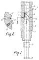
- the fuel injection pump 1, shown in axial view in Fig. 1, comprises a barrel 2, in which a plunger 3 is movable.
- the barrel 2 is adapted to be built into a pump housing of conventional design, which comprises a supply chamber surrounding the middle portion of the barrel and to which excess fuel may be diverted, and from where, during the course of the return stroke of the plunger, fuel may be supplied to the barrel.
- the plunger 3 comprises an upper edge 4 formed between the end and side surfaces of the plunger.
- the plunger moreover, comprises a recess 5, which in the direction of the end surface of the plunger is defined by an oblique cut-off edge 6 extending helically along the side surface of the plunger.
- the oblique cut-off edge 6 covers an angle of for instance 120°, and normally a plunger is provided with two oppositely positioned cut-off edges 6.
- the plunger 2 is provided with coupling means 7 for a rotating mechanism, by means of which the plunger may be rotated for adjustment of the delivery amount, and coupling means 8 for a roller guide adapted to move the plunger axially. These mechanisms are not part of the invention and may be conventionally designed.
- the plunger 3 also comprises an axial duct 9 connecting the recess 5 with the space 10 above the end surface of the plunger 4.
- the pump is adapted to deliver a variable amount of fuel to the injection nozzles in the working cylinders of a diesel engine.
- the delivery amount is adjusted by rotating of the plunger 3.
- the effective pump stroke is initiated by the fact that the edge at the end surface 4 of the plunger during its upwards movement covers a set of timing and cut-off holes 11 in the barrel 2 of the pump, and the effective pump stroke ends, when the oblique cut-off edge 6 uncovers a set of relief holes 12, whereby the pressure in the pump chamber above the end surface 4 of the plunger is relieved through the axial duct 9, the recess 5 and the cut-off holes 12 to the supply chamber surrounding the barrel 2.
- timing holes can be designed such that cavitation stemming from disruption of the flow of fuel, which is expelled at big velocity, is effectively prevented
- relief holes are designed such that a suitable dampening of the diverted fuel is obtained, until the risk of pressure oscillations, which may lead to penetration of cylinder gasoline into the injection nozzles, has been overcome, or such that cavitation in the injection nozzles is prevented.
- the bearing surface between the upper portion of the plunger and the wall of the barrel may be given a proper size by an appropriate dimensioning of the axial spacing between the holes 11 and 12.
- the timing holes are conventionally designed with bigger cross section than the relief holes 12.
- the cavitation may, however, according to the invention be most effectively prevented by placing an orifice member 13 at the outlet of the timing hole to the supply chamber, as shown in Fig. 2.
- the orifice member provides such a flow passage that the pressure in the timing hole in front of the orifice member substantially exceeds the pressure in the supply chamber immediately before the cut-off hole is covered, when the edge of the end surface 4 of the plunger passes.
- the flow resistance in the orifice member leads to such a retarded breaking down of the pressure at the side surface of the plunger that no cavitation occurs.
- the relief holes 12, which are uncovered by the oblique cut-off edge 6, are normally designed with a longitudinal profile in the shape of a diffusor and are provided with the smallest cross section at the wall of the barrel.
- the small cross section at the wall of the barrel is desirable in order to obtain a quick exposure of the hole 12 and thus a well-defined pressure relief sequence in the injection system.
- FIG. 3 shows the pressure sequence in a fuel injection pump according to the invention drawn as a function of the crank angle.
- the fully drawn curve indicates the pressure in the pump chamber 10.
- the curve shows that the pressure in the pump chamber starts to increase as soon as the plunger 3 is moved upwards, but the steep increase starts at 14, where the timing holes 11 are covered by the plunger below its upper edge 4.
- the injection nozzles are opened, and at the continued pump stroke the set amount of fuel is injected in the working cylinder of the engine.
- the cut-off holes are uncovered, following which the pressure in the pump chamber falls in a dampened course, which counteracts pressure oscillations in the injection system and thus ensures a correct closing function of the needles in the injection nozzles.
- a dotted line 17 shows the pressure sequence in the chamber between the orifice member and the side of the plunger, the chamber being provided with an appropriately dimensioned orifice member 13. It will be seen that a gradual pressure fall can be obtained, said pressure fall effectively preventing cavitation in the side hole adjacent to the plunger side.
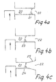
- Figs 4a, 4b and 4c show schematic embodiments of cut-off holes, viewed in longitudinal section.
- Fig. 4a thus shows an embodiment, in which the flow-limiting means in the shape of an orifice member 21 is placed in a cut-off hole 20 close to its outlet 22 into the supply chamber.
- maximum size of the chamber, which is pressurized by cut-off and relief, and consequently the biggest possible volume in the chamber between orifice member and inlet and thus the best possible pressure maintenance is obtained.
- the orifice member may be designed with several ducts or with a flow direction of the ducts under an angle relative to the axis of the cut-off hole.
- the chamber between the wall of the barrel and the orifice member may, moreover, have a non-cylindrical shape.
- the shape may for instance be conical such that the cut-off aperture in the wall of the barrel is somewhat smaller than the diameter of the chamber, in which the orifice member has been inserted. In this way the flow-controlling effect is distributed to the hole in the wall of the barrel and to the orifice member, which may be advantageous, if there are no separate timing and cut-off holes.
- Fig. 4b the orifice member 23 is positioned approximately in the middle of the hole 20, which results in a smaller chamber, but also in a bigger distance from the orifice member 23 to the opposite wall of the supply chamber, where the liquid flowing from the orifice member may cause erosion.
- Fig. 4c shows a preferred embodiment of a cut-off hole 20 provided with an orifice member.
- the orifice member 24 is positioned substantially in the middle of the cut-of hole which in the direction towards the outlet 22 to the supply chamber is designed as a diffusor 25.
- the object of the diffusor 25 is to reduce the velocity of the jet leaving the orifice member.
Landscapes
- Engineering & Computer Science (AREA)
- Chemical & Material Sciences (AREA)
- Combustion & Propulsion (AREA)
- Mechanical Engineering (AREA)
- General Engineering & Computer Science (AREA)
- Fuel-Injection Apparatus (AREA)
Applications Claiming Priority (3)
| Application Number | Priority Date | Filing Date | Title |
|---|---|---|---|
| DK44397 | 1997-04-21 | ||
| DK199700443A DK176162B1 (da) | 1997-04-21 | 1997-04-21 | Brændstofpumpe til forbrændingsmotorer, især store langsomtgående marinedieselmotorer |
| PCT/DK1998/000149 WO1998048166A1 (en) | 1997-04-21 | 1998-04-08 | A fuel injection pump for internal combustion engines, in particular big, slow marine diesel engines |
Publications (2)
| Publication Number | Publication Date |
|---|---|
| EP0977944A1 EP0977944A1 (en) | 2000-02-09 |
| EP0977944B1 true EP0977944B1 (en) | 2002-06-12 |
Family
ID=8093601
Family Applications (1)
| Application Number | Title | Priority Date | Filing Date |
|---|---|---|---|
| EP98916865A Expired - Lifetime EP0977944B1 (en) | 1997-04-21 | 1998-04-08 | A fuel injection pump for internal combustion engines, in particular big, slow marine diesel engines |
Country Status (9)
| Country | Link |
|---|---|
| EP (1) | EP0977944B1 (da) |
| JP (1) | JP3588365B2 (da) |
| KR (1) | KR100440828B1 (da) |
| CN (1) | CN1081740C (da) |
| AU (1) | AU7030298A (da) |
| DE (1) | DE69805999T2 (da) |
| DK (1) | DK176162B1 (da) |
| IT (1) | IT1299426B1 (da) |
| WO (1) | WO1998048166A1 (da) |
Families Citing this family (10)
| Publication number | Priority date | Publication date | Assignee | Title |
|---|---|---|---|---|
| JP3814245B2 (ja) * | 2002-11-21 | 2006-08-23 | ヤンマー株式会社 | 燃料噴射ポンプ |
| JP4098738B2 (ja) * | 2004-03-05 | 2008-06-11 | ボッシュ株式会社 | 内燃機関のための燃料噴射ポンプ |
| KR100895948B1 (ko) | 2004-12-27 | 2009-05-07 | 현대중공업 주식회사 | 캐비테이션 손상 방지구조를 갖는 연료분사펌프 |
| JP2008525704A (ja) * | 2004-12-27 | 2008-07-17 | ヒュンダイ ヘビー インダストリーズ カンパニー リミテッド | キャビテーション損傷防止構造を有する燃料噴射ポンプ |
| RU2407912C2 (ru) * | 2008-07-04 | 2010-12-27 | Открытое акционерное общество "Ярославский завод дизельной аппаратуры" (ОАО "ЯЗДА") | Секция топливного насоса высокого давления |
| KR100992227B1 (ko) | 2008-10-27 | 2010-11-05 | 현대중공업 주식회사 | 디젤엔진 연료분사펌프의 캐비테이션 손상방지장치 |
| DE102017202310A1 (de) * | 2017-02-14 | 2018-08-16 | Robert Bosch Gmbh | Drosselelement sowie Niederdruckkreislauf eines Kraftstoffeinspritzsystems mit einem Drosselelement |
| WO2019131049A1 (ja) * | 2017-12-26 | 2019-07-04 | 日立オートモティブシステムズ株式会社 | 燃料供給ポンプ |
| DE102019116353B4 (de) * | 2019-06-17 | 2020-12-24 | Man Energy Solutions Se | Kraftstoffpumpe |
| CN115614200A (zh) * | 2022-11-08 | 2023-01-17 | 南岳电控(衡阳)工业技术股份有限公司 | 一种船用重型单体泵防止柱塞工作表面穴蚀的结构 |
Family Cites Families (4)
| Publication number | Priority date | Publication date | Assignee | Title |
|---|---|---|---|---|
| GB1271799A (en) * | 1968-09-24 | 1972-04-26 | Cav Ltd | Fuel injection pumps |
| US4118156A (en) * | 1976-12-01 | 1978-10-03 | Sulzer Brothers Limited | Fuel injection pump having choke means in overflow line |
| DE3820707A1 (de) * | 1988-06-18 | 1989-12-21 | Bosch Gmbh Robert | Einspritzpumpe fuer brennkraftmaschinen |
| DE3820706A1 (de) * | 1988-06-18 | 1989-12-21 | Bosch Gmbh Robert | Einspritzpumpe fuer brennkraftmaschinen |
-
1997
- 1997-04-21 DK DK199700443A patent/DK176162B1/da not_active IP Right Cessation
-
1998
- 1998-04-08 EP EP98916865A patent/EP0977944B1/en not_active Expired - Lifetime
- 1998-04-08 DE DE69805999T patent/DE69805999T2/de not_active Expired - Lifetime
- 1998-04-08 CN CN988043572A patent/CN1081740C/zh not_active Expired - Fee Related
- 1998-04-08 KR KR10-1999-7009694A patent/KR100440828B1/ko not_active Expired - Lifetime
- 1998-04-08 WO PCT/DK1998/000149 patent/WO1998048166A1/en not_active Ceased
- 1998-04-08 JP JP54475598A patent/JP3588365B2/ja not_active Expired - Fee Related
- 1998-04-08 AU AU70302/98A patent/AU7030298A/en not_active Abandoned
- 1998-04-20 IT IT98RM000248A patent/IT1299426B1/it active IP Right Grant
Also Published As
| Publication number | Publication date |
|---|---|
| DE69805999D1 (de) | 2002-07-18 |
| ITRM980248A0 (it) | 1998-04-20 |
| KR100440828B1 (ko) | 2004-07-19 |
| AU7030298A (en) | 1998-11-13 |
| ITRM980248A1 (it) | 1999-10-20 |
| DK176162B1 (da) | 2006-10-23 |
| DE69805999T2 (de) | 2002-11-28 |
| IT1299426B1 (it) | 2000-03-16 |
| WO1998048166A1 (en) | 1998-10-29 |
| JP3588365B2 (ja) | 2004-11-10 |
| DK44397A (da) | 1998-10-22 |
| KR20010020139A (ko) | 2001-03-15 |
| EP0977944A1 (en) | 2000-02-09 |
| CN1252854A (zh) | 2000-05-10 |
| CN1081740C (zh) | 2002-03-27 |
| JP2001520719A (ja) | 2001-10-30 |
Similar Documents
| Publication | Publication Date | Title |
|---|---|---|
| US4648369A (en) | Pressure valve | |
| US5522550A (en) | Injection nozzle for internal combustion engines | |
| US5765755A (en) | Injection rate shaping nozzle assembly for a fuel injector | |
| GB1577092A (en) | Pumping nozzle for internal combustion engines | |
| US4036192A (en) | Engine fuel injection system | |
| EP0977944B1 (en) | A fuel injection pump for internal combustion engines, in particular big, slow marine diesel engines | |
| US6152111A (en) | Fuel injection valve for internal combustion engines | |
| US3963384A (en) | Erosion-preventing device for a lift-and-force pump | |
| CZ298185B6 (cs) | Vstrikovací zarízení pro vstrikovací systém paliva s vysokotlakým zásobníkem paliva | |
| EP0698733B1 (en) | Pressure regulation valve | |
| JP2506488B2 (ja) | 燃料噴射ポンプ | |
| US4407253A (en) | Fuel injection pump for self-igniting internal combustion engines | |
| US6105879A (en) | Fuel injection valve | |
| US4964789A (en) | Fuel injection pump for internal combustion engines | |
| EP1604104B1 (en) | Control valve arrangement | |
| GB2279706A (en) | Fuel injection pumping system | |
| US5899385A (en) | Fuel injection valve for internal combustion engines | |
| US6276335B1 (en) | Fuel injection valve | |
| DE3148214C2 (da) | ||
| EP0844383B1 (en) | Injector | |
| US4840310A (en) | Fuel injection nozzle | |
| US4711221A (en) | Fuel injection pump | |
| US4090819A (en) | Fuel injection pump with cavitation preventing steps along the fuel return flow path | |
| US5221196A (en) | Fuel injection pump for internal combustion engines | |
| GB2261477A (en) | Fuel-injection pumps for internal combustion engines |
Legal Events
| Date | Code | Title | Description |
|---|---|---|---|
| PUAI | Public reference made under article 153(3) epc to a published international application that has entered the european phase |
Free format text: ORIGINAL CODE: 0009012 |
|
| 17P | Request for examination filed |
Effective date: 19990923 |
|
| AK | Designated contracting states |
Kind code of ref document: A1 Designated state(s): DE FR GB IT NL |
|
| GRAG | Despatch of communication of intention to grant |
Free format text: ORIGINAL CODE: EPIDOS AGRA |
|
| 17Q | First examination report despatched |
Effective date: 20010615 |
|
| GRAG | Despatch of communication of intention to grant |
Free format text: ORIGINAL CODE: EPIDOS AGRA |
|
| GRAG | Despatch of communication of intention to grant |
Free format text: ORIGINAL CODE: EPIDOS AGRA |
|
| GRAH | Despatch of communication of intention to grant a patent |
Free format text: ORIGINAL CODE: EPIDOS IGRA |
|
| GRAH | Despatch of communication of intention to grant a patent |
Free format text: ORIGINAL CODE: EPIDOS IGRA |
|
| GRAA | (expected) grant |
Free format text: ORIGINAL CODE: 0009210 |
|
| AK | Designated contracting states |
Kind code of ref document: B1 Designated state(s): DE FR GB IT NL |
|
| REG | Reference to a national code |
Ref country code: GB Ref legal event code: FG4D |
|
| REF | Corresponds to: |
Ref document number: 69805999 Country of ref document: DE Date of ref document: 20020718 |
|
| ET | Fr: translation filed | ||
| PLBE | No opposition filed within time limit |
Free format text: ORIGINAL CODE: 0009261 |
|
| STAA | Information on the status of an ep patent application or granted ep patent |
Free format text: STATUS: NO OPPOSITION FILED WITHIN TIME LIMIT |
|
| 26N | No opposition filed |
Effective date: 20030313 |
|
| REG | Reference to a national code |
Ref country code: FR Ref legal event code: PLFP Year of fee payment: 18 |
|
| REG | Reference to a national code |
Ref country code: FR Ref legal event code: PLFP Year of fee payment: 19 |
|
| PGFP | Annual fee paid to national office [announced via postgrant information from national office to epo] |
Ref country code: NL Payment date: 20160420 Year of fee payment: 19 |
|
| PGFP | Annual fee paid to national office [announced via postgrant information from national office to epo] |
Ref country code: GB Payment date: 20160421 Year of fee payment: 19 Ref country code: DE Payment date: 20160421 Year of fee payment: 19 |
|
| PGFP | Annual fee paid to national office [announced via postgrant information from national office to epo] |
Ref country code: IT Payment date: 20160427 Year of fee payment: 19 Ref country code: FR Payment date: 20160421 Year of fee payment: 19 |
|
| REG | Reference to a national code |
Ref country code: DE Ref legal event code: R119 Ref document number: 69805999 Country of ref document: DE |
|
| REG | Reference to a national code |
Ref country code: NL Ref legal event code: MM Effective date: 20170501 |
|
| GBPC | Gb: european patent ceased through non-payment of renewal fee |
Effective date: 20170408 |
|
| REG | Reference to a national code |
Ref country code: FR Ref legal event code: ST Effective date: 20171229 |
|
| PG25 | Lapsed in a contracting state [announced via postgrant information from national office to epo] |
Ref country code: FR Free format text: LAPSE BECAUSE OF NON-PAYMENT OF DUE FEES Effective date: 20170502 Ref country code: DE Free format text: LAPSE BECAUSE OF NON-PAYMENT OF DUE FEES Effective date: 20171103 Ref country code: NL Free format text: LAPSE BECAUSE OF NON-PAYMENT OF DUE FEES Effective date: 20170501 |
|
| PG25 | Lapsed in a contracting state [announced via postgrant information from national office to epo] |
Ref country code: GB Free format text: LAPSE BECAUSE OF NON-PAYMENT OF DUE FEES Effective date: 20170408 |
|
| PG25 | Lapsed in a contracting state [announced via postgrant information from national office to epo] |
Ref country code: IT Free format text: LAPSE BECAUSE OF NON-PAYMENT OF DUE FEES Effective date: 20170408 |