EP0977519B1 - Verfahren und vorrichtung zur bearbeitung von werkstücken in der dentaltechnik - Google Patents
Verfahren und vorrichtung zur bearbeitung von werkstücken in der dentaltechnik Download PDFInfo
- Publication number
- EP0977519B1 EP0977519B1 EP98913681A EP98913681A EP0977519B1 EP 0977519 B1 EP0977519 B1 EP 0977519B1 EP 98913681 A EP98913681 A EP 98913681A EP 98913681 A EP98913681 A EP 98913681A EP 0977519 B1 EP0977519 B1 EP 0977519B1
- Authority
- EP
- European Patent Office
- Prior art keywords
- model
- workpiece
- digital
- dental
- control signals
- Prior art date
- Legal status (The legal status is an assumption and is not a legal conclusion. Google has not performed a legal analysis and makes no representation as to the accuracy of the status listed.)
- Expired - Lifetime
Links
- 238000000034 method Methods 0.000 title claims abstract description 27
- 238000012545 processing Methods 0.000 title abstract description 25
- 238000005516 engineering process Methods 0.000 title abstract description 4
- 230000005855 radiation Effects 0.000 claims abstract description 25
- 238000000227 grinding Methods 0.000 claims abstract description 5
- 238000005520 cutting process Methods 0.000 claims abstract 2
- 239000000463 material Substances 0.000 claims description 23
- 238000003754 machining Methods 0.000 claims description 22
- 230000005540 biological transmission Effects 0.000 claims description 16
- 238000004519 manufacturing process Methods 0.000 claims description 10
- 230000003287 optical effect Effects 0.000 claims description 6
- 239000011248 coating agent Substances 0.000 claims 2
- 238000000576 coating method Methods 0.000 claims 2
- 238000007493 shaping process Methods 0.000 claims 2
- 239000011505 plaster Substances 0.000 abstract description 5
- 238000006243 chemical reaction Methods 0.000 description 6
- 239000010970 precious metal Substances 0.000 description 6
- 238000012546 transfer Methods 0.000 description 5
- 238000005259 measurement Methods 0.000 description 4
- 238000003801 milling Methods 0.000 description 4
- 238000003860 storage Methods 0.000 description 3
- 238000004140 cleaning Methods 0.000 description 2
- 230000001427 coherent effect Effects 0.000 description 2
- 239000007769 metal material Substances 0.000 description 2
- 229920003023 plastic Polymers 0.000 description 2
- 239000004033 plastic Substances 0.000 description 2
- 238000013519 translation Methods 0.000 description 2
- 239000010953 base metal Substances 0.000 description 1
- 239000000919 ceramic Substances 0.000 description 1
- 238000005094 computer simulation Methods 0.000 description 1
- 238000004141 dimensional analysis Methods 0.000 description 1
- 238000009826 distribution Methods 0.000 description 1
- 238000005553 drilling Methods 0.000 description 1
- 230000000694 effects Effects 0.000 description 1
- 230000006870 function Effects 0.000 description 1
- 229910052602 gypsum Inorganic materials 0.000 description 1
- 239000010440 gypsum Substances 0.000 description 1
- 229910000923 precious metal alloy Inorganic materials 0.000 description 1
- 238000005070 sampling Methods 0.000 description 1
- 238000000926 separation method Methods 0.000 description 1
- 239000007858 starting material Substances 0.000 description 1
- 238000012144 step-by-step procedure Methods 0.000 description 1
- 238000011144 upstream manufacturing Methods 0.000 description 1
Images



Classifications
-
- A—HUMAN NECESSITIES
- A61—MEDICAL OR VETERINARY SCIENCE; HYGIENE
- A61C—DENTISTRY; APPARATUS OR METHODS FOR ORAL OR DENTAL HYGIENE
- A61C13/00—Dental prostheses; Making same
- A61C13/0003—Making bridge-work, inlays, implants or the like
- A61C13/0004—Computer-assisted sizing or machining of dental prostheses
Definitions
- the invention relates to a method for machining workpieces in dental technology Machining and / or grinding, the surface contour of a rotatable dental model is scanned and reflected with the aid of a concentrated radiation, the reflected Radiation by means of at least one radiation detector which can be moved parallel to the axis of rotation of the model recorded and as a three-dimensional image in a grid of digitally coded Coordinate values are converted, which are stored in at least one digital computer, the computer having control signals after creating an internal three-dimensional digital model for a machining station for machining the workpiece using a tool derives the coordinate values.
- the invention further relates to a device for performing the method, the device a measuring device with a radiation source for emitting bundled Radiation and at least two radiation detectors for determining the surface contour of one Dental model rotatably arranged by means of reflected radiation based on optical Has triangulation and the measurement device connected to a digital computer is whose output is connected to a control signal input of a processing station is.
- dental model here includes plaster models as an impression of the upper or lower jaw and wax model;
- the workpiece is the starting material for the blank to be created, from which the prosthetic denture is subsequently formed.
- EP 0 671 679 A1 discloses a method for the contactless measurement of three-dimensional objects based on optical triangulation, the bundled radiation emitted by a radiation source scanning the surface of the object and being reflected by it, the reflectance being detected by means of radiation detectors; the object is scanned in a ring-like manner, with a step-by-step, continuous scanning in the Z direction taking place after each revolution and the data obtained in this manner in a ring-like manner being stored and used for the three-dimensional reconstruction of the object by means of a data processing unit; To avoid the effects of undercuts or hidden areas, the ring-wise scanning is carried out at a predetermined Z-scanning step at different angular positions of the scanning head which can be moved together with the radiation source; if necessary, scans are repeated.
- the processing machine can have a multiplicity of tools, the processing sequence of which is selected numerically, the numerical control signals controlling the advancing or retracting of the workpiece and tool and relative moments against one another.
- a milling machine or a laser beam device can be used as the numerically controlled machine tool.
- DE 36 13 096 A1 describes a method for machining workpieces with a programmed multi-axis robot known to scan a laser beam along a three-dimensional Performs workpiece contour using a three-dimensional profile NC program
- the marking is scanned using a sensor guided by the multi-axis robot that controls the axes of the robot so that the sensor always follows the markings and the coordinates of the sensor in the NC control as program points at specified points can be entered and then the workpieces based on this NC program to be edited;
- a TV camera sensor is provided for scanning the markings the tool normal or tool height to the workpiece surface is determined, so that at least at the specified points the TV camera sensor is normal or at the set tool distance (perpendicular) to the workpiece surface.
- EP 0 490 848 B1 also describes a method for producing individually shaped three-dimensional Bodies containing at least parts of artificial dentures, dental bridges and Connections, support parts for the reconstruction of tissue structure and tools for the Manufacture of such dentures, supporting parts, bridges and connections or parts thereof are to be known, the respective model rotating simultaneously and by means of a scanning device is scanned at a certain angle with respect to the axis of rotation of the scanned model; a computer-internal representation is then transmitted via a connection in a telecommunications network with transmitting and receiving devices, the workpiece being in an angular relationship between the blank and the tool is processed and the preferred angular range is within 30 to 60 °.
- the invention is based on EP 0 671 679 or the corresponding DE 44 07 518 C2 the task of a method and an apparatus for producing individual Dentures made of metallic and non-metallic materials according to non-contact optical Specification of dental or wax models specify, both manufacturing costs manufacturing times should also be reduced. Furthermore, it should be economical and qualitative optimal use of metallic or non-metallic materials - especially when using precious metal - during production.
- the object is achieved according to the method by the method steps in the characterizing part of claim 1.
- the reflected radiation is by means of two radiation detectors movable parallel to the axis of rotation of the model; can after creating at least one further digital model in the computer, the data is sent to a digital one Receiving and collecting device are transmitted, the records with regard to the Size of the body to be created and the desired material on at least two processing stations be distributed.
- a major advantage of the specified solution is that models are different Forms and different material properties in different processing stations can be produced, whereby the transfer of the model file without modulation and demodulation via a digital transmission system (possibly bus structure) - such as, for example Optobus / SCI or ISDN network can be done.
- a digital transmission system possibly bus structure
- a holder that can be moved by six degrees of freedom a program-controlled handling system - hereinafter robot or robot holder called - the workpiece against a processing station with inserted tool; the robot holder and tool processing station can also be translated be movable against each other, so that for example several tools on the robot are guided past or the robot at several stationary tool stations is guided past in order to be able to carry out different processing operations.
- a program-controlled handling system hereinafter robot or robot holder called - the workpiece against a processing station with inserted tool
- the robot holder and tool processing station can also be translated be movable against each other, so that for example several tools on the robot are guided past or the robot at several stationary tool stations is guided past in order to be able to carry out different processing operations.
- the surface contour of a dental model is first scanned and stored; after applying wax to the dental model, the Surface contour of the wax model is scanned in a second step using a laser beam and its associated surface coordinate values are saved and in a third step the internal coordinate values of the dental model and wax model become an internal one areal three-dimensional model of the blank to be produced.
- the shape of the later blank is based on a normal wax model is specified, which by means of the usual in the dental laboratory Practice can be created.
- a dental model or to scan a coated dental model with a laser beam the associated Save coordinate values and after building the wax model this from the dental model remove and in a third step the surface of the removed Wax model to be scanned using a laser beam to get from the surface coordinate values to build an internal three-dimensional model of the blank to be produced; here the multiple scanning according to EP 0 671 679 A1 mentioned above proves to be Particularly advantageous to take into account undercuts in the model.
- a transmission method it is also advantageously possible to use model scanning and to spatially separate blank production from one another, the surface coordinate values then of the internally stored model together with identification signals for material information and customer via a digital data transmission route with high throughput - such as Optobus / SCl or ISDN - are transmitted; here it turns out to be advantageous that blanks made of different materials with optimal use of the Workpieces can be manufactured.
- the object is achieved in that a workpiece captured by workpiece measuring station as a blank with the surface contour of the dental model, a model comparator designed as a digital computer
- the processing station has at least one Machine tool and a robot which has at least one holder for receiving of the workpiece or tool, with the holder by all six degrees of freedom is movable and six drive elements controllable by the computer are provided by which each have three elements control signals for the 3 degrees of freedom of translation and each three elements receive control signals for the 3 degrees of freedom of rotation.
- the robot has a holder for positioning the Workpiece, the associated digital computer each having control signals for three degrees of freedom the translation and for three degrees of freedom of rotation of the holder; advantageously It is possible to use different robots one after the other to go through, including a serial creation of different, individual dentures is possible if there is a relative movement between the robot and the tool processing is provided. It is also possible to have a raw machining station and a separate one Provide station for fine machining.
- the holder for positioning the workpiece is preferably guided by means of a robot arm.
- digital information about at least two models from a collecting device to suitable processing stations transfer; it proves to be particularly advantageous here that pro Processing station is only a single material to be processed, so that intermediate cleaning processes when changing material from blank to blank Model scanning and receiving and collecting device - such as ISDN - spatially separated be, the connection via a digital transmission system, digital network as well as system with bus structure if necessary.
- FIG. 1a there is initially a plaster model as a dental model 1 (jaw impression) in a measuring device 3, which on the basis of optical triangulation by means of a Device 4 according to EP 0 671 679 A1 the surface coordinates X1, Y1, Z1 of the axis 5 rotating dental model 1 and this after an analog / digital conversion to analog / digital converter 6 in a digital computer 7 for creating an internal digital model of dental model 1 stores. Furthermore, a wax model is subsequently used as a dental model 2 introduced as a template for the blank to be created later in the measuring device 3 and its surface coordinate values X2, Y2, Z2 also with rotation of the dental model 2 determined and saved.
- Figure 1b The corresponding components of the device are in Figure 1b is shown schematically, wherein in Figure 1a with reference numeral 1, 2, the model creation is symbolically represented for both plaster model and wax model, while the surveying device with reference number 3, the analog / digital conversion into converter with number 6 and the storage device is shown as part of a digital computer 7.
- the gypsum model 1 (example tooth stump) is used as a measurement device 3 also the wax model 2 (corresponds to the later blank for prosthetic dentures) in each case sampled with the coordinate values X1, Y1, Z1 and X2, Y2, Z2 and after analog / digital conversion and creation of a computer-internal digital model in a digital computer Model comparator 8 fed via its input 9, comparator 8 still receiving a signal via input 10, which receives an internal digital model of the workpiece 12 for the later one To form blank.
- the workpiece 12 is input 13 of a workpiece measurement station 14 supplied, similar to the units 6 and 7, an analog / digital conversion in analog / digital converter 15 and in the memory of digital computer 16 an internal digital model of the workpiece with identification information about the workpiece properties created; however, it is also possible to determine the workpiece geometry and, if necessary, the workpiece property Enter via an on-screen keyboard or read in via optical coding allow.
- the workpiece geometry values are then via output 17 of the digital computer 16 and input 10 to the model comparator 8, the digital Dental model as a plaster model 1 and as a wax model 2 with the determined model of the workpiece 12 is compared to make optimal use of the workpiece volume. The selection of the material belonging to the respective model is taken into account.
- the model comparator 8 is connected to a collector and distributor station 20 via output 11, which different models M1, M2, M3 to be created on different processing stations B1, B2, B3 distributed, with only one station B1 in FIG. 1a for simplification is shown; a specific material is to be assigned to each processing station his;
- the exit 21 of the collector and distribution station 20 is with an entrance 22 connected to a numerical processor controller 23; multiple outputs 25 ', 25 ", 26', 26" 27 ', 27 "of the processor controller 23 are used to control the robot 28 and the machine tool 29 existing processing stations B1, B2, B3, with outputs 25 ', 26 ', 27' are the robots 28 each working in six degrees of freedom A1, A2, A3, A4, A5, A6 are controlled, while the actual machine tools 29, for milling, grinding, Drilling can be controlled via output 25 ", 26", 27 ".
- 12 blanks to be created are each designated 31, 32, 33; You should increasingly more similar during processing to the models M1, M2, M3 to be created become.
- the angle of attack between the working axis of the tool such as Drill or The milling machine and the working axis of the robot arm for holding the workpiece lie in the area of ⁇ 180 °.
- FIG. 1a This operation is shown schematically in FIG. 1a, with the axes or degrees of freedom A1, A2, A3, A4, A5, A6 of the robot are shown symbolically.
- the respective Machine tool is designated by number 29.
- Using one connected to the digital computer Screen is the placement of the digital dental model in the digital workpiece model to be observed on a screen 36, so that in the event of incorrect placement or incorrect format of the workpiece 12 (if necessary manually) and a new workpiece can be introduced.
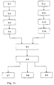
- step S1 the dental model and the wax model are measured in succession
- step S2 the determined data are converted into digital values
- step S3 the digital values of the coordinate points stored numerically, i.e. in a digital memory as File of a digital computer recorded and, if necessary, interpolated to display the area and then in step S 4 fed to a digital comparator.
- Parallel to the model scan the workpiece is measured in step S11, the values determined there being carried out in step S12 are converted into digital values and the digital values obtained in a digital memory in step S13 are fed and stored as a file in a digital computer;
- steps S11, S12 and the workpiece geometry or material property to enter a digital computer directly in step S13.
- step S14 via the workpiece to the digital model comparator and compared in step S5 in the digital comparator with the digital values of the model, with an optimal placement of the digitized dental model within the volume of the digitized workpiece with optimal use of materials.
- step S6 Machining station each of the three machining stations provided here If necessary, only process blanks made of a certain material in step S7, S8, S9 should, if possible, unnecessary intermediate cleaning of the tools when changing materials to avoid.
- steps S7, S8, S9 the workpiece is guided by a robot arm using a holder, the robot arm being movable through all six degrees of freedom; the workpiece is guided against machine tools, which via a numerical tool control can be controlled in each case.
- Figure 2 is for remote transmission of digital memory contents of the digital dental model directed, sampling, analog / digital conversion and building a digital three-dimensional Figure 1b expires, but the transmission of the digital Dental model and wax model via a digital transmission link 37 - such as Bus system, or ISDN line - is provided, which is spatially separated from the first computer 7, second computer 38 removes a new structure of the digital dental model accordingly Dental model 1, 2 made possible by means of the transmitted digital values; continues to be a Transmission of identification signal, material properties and customer or patient file performed.
- a digital transmission link 37 - such as Bus system, or ISDN line -
Landscapes
- Health & Medical Sciences (AREA)
- General Health & Medical Sciences (AREA)
- Dentistry (AREA)
- Epidemiology (AREA)
- Life Sciences & Earth Sciences (AREA)
- Animal Behavior & Ethology (AREA)
- Oral & Maxillofacial Surgery (AREA)
- Public Health (AREA)
- Veterinary Medicine (AREA)
- Dental Tools And Instruments Or Auxiliary Dental Instruments (AREA)
- Numerical Control (AREA)
- Dental Prosthetics (AREA)
- Manipulator (AREA)
- Dental Preparations (AREA)
Description
Aus der EP 0 671 679 A1 ist ein Verfahren zum berührungslosen Vermessen dreidimensionaler Objekte auf der Basis optischer Triangulation bekannt, wobei die von einer Strahlungsquelle ausgesendete, gebündelte Strahlung die Oberfläche des Objekts abtastet und von dieser reflektiert wird, wobei die Remission mittels Strahlungsdetektoren erfasst wird; das Objekt wird dabei ringweise abgetastet, wobei nach jeder Umdrehung ein schrittweises, fortlaufendes Abtasten in Z-Richtung erfolgt und die derart ringweise gewonnenen Daten abgespeichert und zur drei-dimensionalen Rekonstruktion des Objektes mittels einer Datenverarbeitungseinheit verwendet werden; zur Vermeidung der Auswirkungen von Hinterschneidungen oder verdeckten Stellen wird das ringweise Abtasten bei einem vorgegebenen Z-Abtastschritt unter unterschiedlichen Winkelstellungen des zusammen mit der Strahlungsquelle bewegbaren Abtastkopfes durchgeführt; ggf. werden Abtastungen wiederholt.
Die Bearbeitungsmaschine kann eine Vielzahl von Werkzeugen aufweisen, deren Bearbeitungsfolge numerisch ausgewählt wird, wobei die numerischen Steuersignale vorschiebend oder zurückziehend von Werkstück und Werkzeug sowie relative Momente gegeneinander steuern. Als numerisch gesteuerte Werkzeugmaschine kann beispielsweise eine Fräsmaschine oder eine Laserstrahl-Vorrichtung eingesetzt werden.
Claims (14)
- Verfahren zur Bearbeitung von Werkstücken (12) in der Dentaltechnik mittels Zerspanung und/oder Schleifen, wobei die Oberflächenkontur eines drehbaren Dentalmodells (1, 2) mit Hilfe einer gebündelten Strahlung abgetastet und reflektiert wird, wobei reflektierte Strahlung mittels wenigstens eines parallel zur Drehachse des Modells bewegbaren Strahlungsdetektors erfasst und als dreidimensionale Abbildung in ein Raster von digital codierten Koordinaten-Werten konvertiert wird (6), die in wenigstens einem ersten Digital-Rechner (7) gespeichert werden, wobei der erste Rechner (7) nach Erstellung eines internen dreidimensionalen Digital-Modells Steuersignale für eine Bearbeitungsstation (B1) zur Bearbeitung des Werkstücks (12) mittels Werkzeug aus den Koordinaten-Werten ableitet, dadurch gekennzeichnet, dass einem Modellkomparator und einer als zweiter Rechner ausgebildeten digitalen Sammler- und Verteilerstation (20) Informationen über die Geometrie des zu bearbeitenden Werkstücks (12) zugeführt werden, aus denen eine interne dreidimensionale Werkstück-Abbildung erstellt wird, diese mit einer internen dreidimensionalen Abbildung wenigstens eines Modells (1, 2) verglichen wird und Steuersignale (21) zur optimalen Ausnutzung des Volumens des Werkstücks (12) bei Bildung wenigstens eines Rohlings ausgegeben werden, wobei vom zweiten Rechner jeweils wenigstens drei Steuersignale für eine relative Translations-Bewegung und jeweils wenigstens drei Steuersignale für eine relative Rotations-Bewegung zwischen Werkzeug und Werkstück (12) zur Herstellung wenigstens eines Rohlings aus dem Werkstück (12) ausgegeben werden.
- Verfahren nach Anspruch 1, dadurch gekennzeichnet, dass die reflektierte Strahlung mittels zweier parallel zur Drehachse (5) des Modells (1, 2) bewegbarer Strahlungsdetektoren erfasst wird.
- Verfahren nach Anspruch 1 oder 2, dadurch gekennzeichnet, dass nach Erstellung wenigstens eines weiteren Digital-Modells im ersten Rechner die Daten an die digitale Sammler- und Verteilerstation (20) übertragen werden, die Datensätze hinsichtlich der Größe der zur erstellenden Körper und des gewünschten Werkstoffs auf wenigstens zwei Bearbeitungsstationen verteilt.
- Verfahren nach einem der Ansprüche 1 bis 3, dadurch gekennzeichnet, dass die Daten mittels einer Bus-Übertragungsstrecke oder digitale Übertragungsstrecke an die digitale Sammler- und Verteilerstation (20) übertragen werden.
- Verfahren nach einem der Ansprüche 1 bis 4, dadurch gekennzeichnet, dass wenigstens zwei interne dreidimensionale Modelle zur Bildung von wenigstens zwei Rohlingen aus einem einzigen Werkstück (12) mit dessen interner dreidimensionaler Abbildung verglichen werden.
- Verfahren nach einem der Ansprüche 1 bis 5, dadurch gekennzeichnet, dass die Steuersignale einer als Roboter (28) dienenden Bearbeitungsstation zur Bewegungssteuerung wenigstens einer Halterung in allen sechs Freiheitsgraden zugeführt werden, wobei in der Halterung das Werkstück und/oder das Werkzeug geführt wird.
- Verfahren nach einem der Ansprüche 1 bis 6, dadurch gekennzeichnet, dass in einem ersten Schritt wenigstens die Oberflächenkontur eines Dentalmodells (1, 2) oder eines mit einer Beschichtung versehenen Dentalmodells mittels Laserstrahl abgetastet und die zugehörigen Oberflächen-Koordinaten-Werte gespeichert werden, dass nach Aufbringung von Wachs auf das Dentalmodell (1, 2) ein Wachsmodell entsteht, dessen Oberflächenkontur in einem zweiten Schritt mittels Laserstrahl abgetastet wird, wobei dessen zugehörige Oberflächen-Koordinatenwerte gespeichert werden und dass in einem dritten Schritt aus den Oberflächen-Koordinatenwerten von Dentalmodell (1, 2) und Wachsmodell ein internes dreidimensionales Modell des herzustellenden Rohlings erstellt wird.
- Verfahren nach einem der Ansprüche 1 bis 6, dadurch gekennzeichnet, dass in einem ersten Schritt wenigstens die Oberflächenkontur eines Dentalmodells (1, 2) oder eines mit einer Beschichtung versehenen Dentalmodells mittels Laserstrahl abgetastet und die zugehörigen Oberflächen-Koordinaten-Werte gespeichert werden, dass nach Aufbringung von Wachs auf das Dentalmodell (1, 2) ein Wachsmodell entsteht, das in einem zweiten Schritt wieder vom Dentalmodell (1, 2) abgenommen wird und dass in einem dritten Schritt die Oberfläche des abgenommenen Wachsmodells mittels Laserstrahl abgetastet und aus den Oberflächen-Koordinaten-Werten ein internes dreidimensionales Modell des herzustellenden Rohlings erstellt wird.
- Verfahren nach einem der Ansprüche 1 bis 8, dadurch gekennzeichnet, dass die Oberflächen-Koordinaten-Werte des intern gespeicherten Modells des Rohlings als Steuersignale mittels digitalem Übertragungssystem zur Bearbeitung des Werkstücks weitergeleitet werden.
- Verfahren nach Anspruch 9, dadurch gekennzeichnet, dass die Steuersignale zusammen mit Identifikationssignalen für Werkstoffangaben und Auftraggeber weitergeleitet werden.
- Vorrichtung zur Ausführung des Verfahrens nach Anspruch 1, wobei die Vorrichtung eine Vermessungseinrichtung (3) mit einer Strahlungsquelle zur Abgabe gebündelter Strahlung und wenigstens zwei Strahlungsdetektoren zur Ermittlung der Oberflächenkontur eines drehbar angeordneten Dentalmodells (1, 2) mittels reflektierter Strahlung auf der Basis optischer Triangulation aufweist und die Vermessungseinrichtung (3) mit einem ersten Digital-Rechner (7) verbunden ist, dessen Ausgang an einen Steuer-Signal-Eingang einer Bearbeitungsstation (B1, B2, B3) angeschlossen ist, dadurch gekennzeichnet, dass zum Vergleich der Geometrie eines mittels einer Werkstückvermessungsstation (14) erfassten Werkstücks (12) als Rohling mit der Oberflächenkontur des Dentalmodells (1, 2) und zur optimalen Ausnutzung des Werkstücks ein Modellkomparator (8) einer als zweiter Digital-Rechner ausgebildeten Sammler- und Verteilerstation (20) vorgeschaltet ist, dass die Bearbeitungsstation wenigstens eine Werkzeugmaschine (29) und einen Roboter (28) aufweist, der wenigstens eine Halterung zur Aufnahme des Werkstücks (12) oder des Werkzeugs enthält, wobei die Halterung (30) um alle sechs Freiheitsgrade bewegbar ist und sechs vom zweiten Rechner ansteuerbare Antriebselemente vorgesehen sind, von denen jeweils drei Elemente Steuersignale für die 3 Freiheitsgrade der Translation und jeweils drei Elemente Steuersignale für die 3 Freiheitsgrade der Rotation empfangen.
- Vorrichtung nach Anspruch 11, dadurch gekennzeichnet, dass die Halterung (30) zur Positionierung des Werkstücks (12) vorgesehen ist.
- Vorrichtung nach Anspruch 11 oder 12, dadurch gekennzeichnet, dass die digital Sammler- und Verteilerstation (20) zur Verteilung von wenigstens zwei Datensätzen an wenigstens zwei Bearbeitungsstationen vorgesehen ist, wobei jeweils digitale Informationen von der Empfangs- und Sammeleinrichtung an die Bearbeitungsstation übertragen werden.
- Vorrichtung nach Anspruch 13, dadurch gekennzeichnet, dass zwischen den ersten Digital-Rechner (7) und der Sammler - und Verteilerstation (20) ein digitales Übertragungssystem geschaltet ist.
Applications Claiming Priority (3)
| Application Number | Priority Date | Filing Date | Title |
|---|---|---|---|
| DE19710273A DE19710273C1 (de) | 1997-03-13 | 1997-03-13 | Verfahren und Vorrichtung zur Bearbeitung von Werkstücken in der Dentaltechnik |
| DE19710273 | 1997-03-13 | ||
| PCT/EP1998/001333 WO1998040031A1 (de) | 1997-03-13 | 1998-03-06 | Verfahren und vorrichtung zur bearbeitung von werkstücken in der dentaltechnik |
Publications (2)
| Publication Number | Publication Date |
|---|---|
| EP0977519A1 EP0977519A1 (de) | 2000-02-09 |
| EP0977519B1 true EP0977519B1 (de) | 2003-09-17 |
Family
ID=7823156
Family Applications (1)
| Application Number | Title | Priority Date | Filing Date |
|---|---|---|---|
| EP98913681A Expired - Lifetime EP0977519B1 (de) | 1997-03-13 | 1998-03-06 | Verfahren und vorrichtung zur bearbeitung von werkstücken in der dentaltechnik |
Country Status (5)
| Country | Link |
|---|---|
| EP (1) | EP0977519B1 (de) |
| AT (1) | ATE249791T1 (de) |
| DE (2) | DE19710273C1 (de) |
| ES (1) | ES2203940T3 (de) |
| WO (1) | WO1998040031A1 (de) |
Families Citing this family (13)
| Publication number | Priority date | Publication date | Assignee | Title |
|---|---|---|---|---|
| DE19922279A1 (de) * | 1999-05-11 | 2000-11-16 | Friedrich Schiller Uni Jena Bu | Verfahren zur Generierung patientenspezifischer Implantate |
| DE10194867D2 (de) | 2000-11-08 | 2003-11-20 | Willytec Gmbh Technologiezentr | (Dentale) Oberflächenerfassung und Erzeugung |
| DE20104583U1 (de) | 2001-03-14 | 2001-09-06 | Steinhauser, Matthias, 88250 Weingarten | Zahntechnisches Modellierwachs zur Abtastung mit optischen Systemen |
| DE10133568A1 (de) * | 2001-07-13 | 2003-01-30 | Degussa Dental Gmbh & Co Kg | Verfahren und Vorrichtung zur dreidimensionalen Vermessung und Digitalisierung eines Körpers |
| DE10214968B4 (de) * | 2002-04-04 | 2004-07-01 | Griesbeck, Anton, Dr.med.dent. | Verfahren und Vorrichtung zur Rekonstruktion okklusaler Strukturen |
| ES2297241T3 (es) | 2002-10-18 | 2008-05-01 | Aepsilon Rechteverwaltungs Gmbh | Dispositivos y procedimientos para el registro de superficies y para la fabricacion de elementos de protesis dental. |
| EP1574817A1 (de) | 2004-03-10 | 2005-09-14 | Diener&AG&Precision&Machining | Verfahren und Abtastanordnung zum berührungslosen Abtasten dreidimensionaler Objekte und Haltevorrichtung für Objekte |
| ES2436273T3 (es) * | 2004-06-10 | 2013-12-30 | Institut Straumann Ag | Procedimiento y dispositivo para la producción de una prótesis dental |
| WO2007028260A1 (de) * | 2005-09-07 | 2007-03-15 | Lukas Kamer | Verfahren zur herstellung eines führungsorgans zum führen eines chirurgischen instrumentes sowie nach diesem verfahren hergestelltes führungsorgan |
| ES2328430B1 (es) * | 2006-04-06 | 2010-09-16 | Moises Mora Garcia | Maquina de fabricacion de protesis dentales y maxilofaciales a partir de un modelo digital tridimensional mediante aplicacion directa de laser y sinterizacion, y procedimiento de operacion de dicha maquina. |
| DE102012221793B4 (de) * | 2012-11-28 | 2017-11-02 | Westcam Technologies Gmbh | Automatisches Verfahren zum Positionieren eines Prothesenzahnes |
| DE102013204146A1 (de) * | 2013-03-11 | 2014-09-25 | Eos Gmbh Electro Optical Systems | Verfahren zur verzugsfreien Herstellung von Objekten mittels eines generativen Schichtbauverfahrens und solchermaßen hergestelltes Dentalmodell |
| IT201600128948A1 (it) * | 2016-12-20 | 2018-06-20 | Nivol S R L | Apparecchiatura e processo di fabbricazione di dispositivi dentali ortodontici e/o protesici |
Family Cites Families (11)
| Publication number | Priority date | Publication date | Assignee | Title |
|---|---|---|---|---|
| US3861044A (en) * | 1972-05-04 | 1975-01-21 | Jr William E Swinson | Dental fitting process |
| JPS5469896A (en) * | 1977-11-15 | 1979-06-05 | Koyo Seiko Co Ltd | Method of machining work outer surface with laser beam |
| DE2936847A1 (de) * | 1979-09-12 | 1981-03-19 | Paul Dr. 6054 Rodgau Heitlinger | Verfahren zur herstellung von zahnersatz und vorrichtung zur durchfuehrung des verfahrens |
| FR2525103B1 (fr) * | 1982-04-14 | 1985-09-27 | Duret Francois | Dispositif de prise d'empreinte par des moyens optiques, notamment en vue de la realisation automatique de protheses |
| US4663720A (en) * | 1984-02-21 | 1987-05-05 | Francois Duret | Method of and apparatus for making a prosthesis, especially a dental prosthesis |
| DE3613096A1 (de) * | 1986-04-18 | 1987-10-29 | Messer Griesheim Gmbh | Verfahren zum bearbeiten von werkstuecken |
| DE3910855A1 (de) * | 1989-04-04 | 1990-10-11 | Klaus Muehlberger | Vorrichtung und verfahren zum vermessen dreidimensionaler objekte |
| DE59008902D1 (de) * | 1990-05-09 | 1995-05-18 | Siemens Ag | Verfahren und Vorrichtung zur Erstellung von medizinischen, insbesondere zahnmedizinischen Prothetik- Passkörpern. |
| SE468198B (sv) * | 1990-12-12 | 1992-11-23 | Nobelpharma Ab | Foerfarande och anordning foer framstaellning av individuellt utformade tredimensionella kroppar anvaendbara som tandersaettningar, proteser, etc |
| DE4407518C2 (de) * | 1994-03-07 | 1996-01-18 | Intecu Ges Fuer Innovation Tec | Verfahren zum berührungslosen Vermessen dreidimensionaler Objekte auf der Basis optischer Triangulation |
| ATE189321T1 (de) * | 1994-03-07 | 2000-02-15 | Intecu Ges Fuer Innovation Tec | Vorrichtung und verfahren zum berührungslosen vermessen dreidimensionaler objekte auf der basis optischer triangulation |
-
1997
- 1997-03-13 DE DE19710273A patent/DE19710273C1/de not_active Expired - Fee Related
-
1998
- 1998-03-06 ES ES98913681T patent/ES2203940T3/es not_active Expired - Lifetime
- 1998-03-06 AT AT98913681T patent/ATE249791T1/de not_active IP Right Cessation
- 1998-03-06 DE DE59809652T patent/DE59809652D1/de not_active Expired - Fee Related
- 1998-03-06 EP EP98913681A patent/EP0977519B1/de not_active Expired - Lifetime
- 1998-03-06 WO PCT/EP1998/001333 patent/WO1998040031A1/de not_active Ceased
Also Published As
| Publication number | Publication date |
|---|---|
| ES2203940T3 (es) | 2004-04-16 |
| DE59809652D1 (de) | 2003-10-23 |
| ATE249791T1 (de) | 2003-10-15 |
| WO1998040031A1 (de) | 1998-09-17 |
| DE19710273C1 (de) | 1998-08-20 |
| EP0977519A1 (de) | 2000-02-09 |
Similar Documents
| Publication | Publication Date | Title |
|---|---|---|
| EP1246581B8 (de) | Werkzeugmaschine zur herstellung von grundgerüsten für zahnersatz | |
| DE19710273C1 (de) | Verfahren und Vorrichtung zur Bearbeitung von Werkstücken in der Dentaltechnik | |
| DE69413852T2 (de) | Verfahren zur Herstellung einer Prothese die auf im Kieferknochen eines Patienten fixierten Implantaten befestigt wird, und Vorrichtung zur Herstellung derartigen Prothesen | |
| AU713223B2 (en) | Method and device for a product intended to be introduced into the human body, and scanning device for a model of the product | |
| US5452219A (en) | Method of making a tooth mold | |
| EP1406555B1 (de) | Verfahren und vorrichtung zur dreidimensionalen vermessung und digitalisierung eines dentalmodells | |
| EP3487443B1 (de) | Verfahren zur vermessung einer implantat-implantat-situation | |
| DE602005004716T2 (de) | Verfahren zur Erzeugung von dreidimensionalen Formdaten einer Zahnprothese | |
| EP1105067A1 (de) | Verfahren zur rechnergesteuerten herstellung von zahnersatz | |
| EP1245332A1 (de) | Fräs-/Schleifmaschine zur Herstellung von zahnmedizinischen Werkstücken | |
| DE3003435A1 (de) | Verfahren und vorrichtung zur herstellung eines kronenteiles | |
| CH682990A5 (de) | Verfahren zur Herstellung eines Formkörpers, insbesondere zur Herstellung von Inlays, Onlays und Kronen in der Zahnmedizin sowie Gerät zur Durchführung des Verfahrens. | |
| EP0913130A2 (de) | Verfahren und Vorrichtung zur Herstellung eines Zahnersatzteiles | |
| EP2303177A1 (de) | Bearbeitungsvorrichtung zum anfertigen einer bohrschablone für zahnimplantate | |
| WO2005030437A1 (de) | Schleifmaschine mit rundlaufkorrektur | |
| EP3794311B1 (de) | Verfahren, vorrichtung sowie computerprogrammprodukt zum erzeugen eines prüfplans für die prüfung eines messobjekts, verfahren und vorrichtung zum prüfen eines messobjekts | |
| EP0455855B1 (de) | Verfahren und Vorrichtung zur Erstellung von medizinischen, insbesondere zahnmedizinischen Prothetik- Passkörpern | |
| DE4223483A1 (de) | Verfahren zur Bestimmung der Form- und Lageabweichungen von Fertigungsteilen | |
| DE102021125542A1 (de) | Verfahren zum Steuern einer Messvorrichtung und Messvorrichtung | |
| DE3604531A1 (de) | Verfahren zur herstellung von zahnersatzteilen und vorrichtung zur durchfuehrung dieses verfahrens | |
| DE19740044A1 (de) | Verfahren und Vorrichtung zur Bearbeitung von Werkstücken bei der Herstellung von Schmuck oder Designer-Ware | |
| DE102007044000A1 (de) | Verfahren zur Bestimmung einer Raumform eines Werkstücks | |
| EP1471401B1 (de) | Verfahren zur Einmessung des Koordinatensystems einer Kamera eines Roboters gegenüber dem Koordinatensystem des Roboters oder umgekehrt | |
| DE69526654T2 (de) | Verfahren zur Herstellung einer Zahnabgussform | |
| EP2299928A1 (de) | Verfahren zur ermittlung von 3d-daten von zumindest einem präparierten kieferbereich |
Legal Events
| Date | Code | Title | Description |
|---|---|---|---|
| PUAI | Public reference made under article 153(3) epc to a published international application that has entered the european phase |
Free format text: ORIGINAL CODE: 0009012 |
|
| 17P | Request for examination filed |
Effective date: 19990816 |
|
| AK | Designated contracting states |
Kind code of ref document: A1 Designated state(s): AT BE CH DE DK ES FI FR GB GR IE IT LI LU MC NL PT SE |
|
| RAP1 | Party data changed (applicant data changed or rights of an application transferred) |
Owner name: HERAEUS KULZER GMBH & CO.KG |
|
| 17Q | First examination report despatched |
Effective date: 20020711 |
|
| GRAH | Despatch of communication of intention to grant a patent |
Free format text: ORIGINAL CODE: EPIDOS IGRA |
|
| GRAH | Despatch of communication of intention to grant a patent |
Free format text: ORIGINAL CODE: EPIDOS IGRA |
|
| GRAA | (expected) grant |
Free format text: ORIGINAL CODE: 0009210 |
|
| AK | Designated contracting states |
Kind code of ref document: B1 Designated state(s): AT CH DE ES FR GB IT LI NL SE |
|
| RBV | Designated contracting states (corrected) |
Designated state(s): AT CH DE ES FR GB IT LI NL SE |
|
| REG | Reference to a national code |
Ref country code: GB Ref legal event code: FG4D Free format text: NOT ENGLISH |
|
| REG | Reference to a national code |
Ref country code: CH Ref legal event code: NV Representative=s name: KIRKER & CIE SA Ref country code: CH Ref legal event code: EP |
|
| REF | Corresponds to: |
Ref document number: 59809652 Country of ref document: DE Date of ref document: 20031023 Kind code of ref document: P |
|
| REG | Reference to a national code |
Ref country code: IE Ref legal event code: FG4D Free format text: GERMAN |
|
| GBT | Gb: translation of ep patent filed (gb section 77(6)(a)/1977) |
Effective date: 20031217 |
|
| REG | Reference to a national code |
Ref country code: SE Ref legal event code: TRGR |
|
| PGFP | Annual fee paid to national office [announced via postgrant information from national office to epo] |
Ref country code: NL Payment date: 20040227 Year of fee payment: 7 |
|
| PGFP | Annual fee paid to national office [announced via postgrant information from national office to epo] |
Ref country code: CH Payment date: 20040302 Year of fee payment: 7 Ref country code: SE Payment date: 20040302 Year of fee payment: 7 |
|
| PGFP | Annual fee paid to national office [announced via postgrant information from national office to epo] |
Ref country code: AT Payment date: 20040303 Year of fee payment: 7 Ref country code: GB Payment date: 20040303 Year of fee payment: 7 |
|
| PGFP | Annual fee paid to national office [announced via postgrant information from national office to epo] |
Ref country code: DE Payment date: 20040305 Year of fee payment: 7 |
|
| PGFP | Annual fee paid to national office [announced via postgrant information from national office to epo] |
Ref country code: FR Payment date: 20040310 Year of fee payment: 7 |
|
| PGFP | Annual fee paid to national office [announced via postgrant information from national office to epo] |
Ref country code: ES Payment date: 20040322 Year of fee payment: 7 |
|
| REG | Reference to a national code |
Ref country code: ES Ref legal event code: FG2A Ref document number: 2203940 Country of ref document: ES Kind code of ref document: T3 |
|
| REG | Reference to a national code |
Ref country code: IE Ref legal event code: FD4D |
|
| ET | Fr: translation filed | ||
| PLBE | No opposition filed within time limit |
Free format text: ORIGINAL CODE: 0009261 |
|
| STAA | Information on the status of an ep patent application or granted ep patent |
Free format text: STATUS: NO OPPOSITION FILED WITHIN TIME LIMIT |
|
| 26N | No opposition filed |
Effective date: 20040618 |
|
| PG25 | Lapsed in a contracting state [announced via postgrant information from national office to epo] |
Ref country code: IT Free format text: LAPSE BECAUSE OF NON-PAYMENT OF DUE FEES Effective date: 20050306 Ref country code: AT Free format text: LAPSE BECAUSE OF NON-PAYMENT OF DUE FEES Effective date: 20050306 |
|
| PG25 | Lapsed in a contracting state [announced via postgrant information from national office to epo] |
Ref country code: SE Free format text: LAPSE BECAUSE OF NON-PAYMENT OF DUE FEES Effective date: 20050307 Ref country code: ES Free format text: LAPSE BECAUSE OF NON-PAYMENT OF DUE FEES Effective date: 20050307 |
|
| PG25 | Lapsed in a contracting state [announced via postgrant information from national office to epo] |
Ref country code: LI Free format text: LAPSE BECAUSE OF NON-PAYMENT OF DUE FEES Effective date: 20050331 Ref country code: CH Free format text: LAPSE BECAUSE OF NON-PAYMENT OF DUE FEES Effective date: 20050331 |
|
| PG25 | Lapsed in a contracting state [announced via postgrant information from national office to epo] |
Ref country code: NL Free format text: LAPSE BECAUSE OF NON-PAYMENT OF DUE FEES Effective date: 20051001 Ref country code: DE Free format text: LAPSE BECAUSE OF NON-PAYMENT OF DUE FEES Effective date: 20051001 |
|
| EUG | Se: european patent has lapsed | ||
| REG | Reference to a national code |
Ref country code: CH Ref legal event code: PL |
|
| GBPC | Gb: european patent ceased through non-payment of renewal fee |
Effective date: 20050306 |
|
| PG25 | Lapsed in a contracting state [announced via postgrant information from national office to epo] |
Ref country code: FR Free format text: LAPSE BECAUSE OF NON-PAYMENT OF DUE FEES Effective date: 20051130 |
|
| NLV4 | Nl: lapsed or anulled due to non-payment of the annual fee |
Effective date: 20051001 |
|
| REG | Reference to a national code |
Ref country code: FR Ref legal event code: ST Effective date: 20051130 |
|
| REG | Reference to a national code |
Ref country code: ES Ref legal event code: FD2A Effective date: 20050307 |