EP0977285A1 - Charge de pression pour actuateur piezoélectrique - Google Patents
Charge de pression pour actuateur piezoélectrique Download PDFInfo
- Publication number
- EP0977285A1 EP0977285A1 EP99114544A EP99114544A EP0977285A1 EP 0977285 A1 EP0977285 A1 EP 0977285A1 EP 99114544 A EP99114544 A EP 99114544A EP 99114544 A EP99114544 A EP 99114544A EP 0977285 A1 EP0977285 A1 EP 0977285A1
- Authority
- EP
- European Patent Office
- Prior art keywords
- actuator
- hollow
- piezoelectric actuator
- spring means
- piezoelectric
- Prior art date
- Legal status (The legal status is an assumption and is not a legal conclusion. Google has not performed a legal analysis and makes no representation as to the accuracy of the status listed.)
- Granted
Links
- 230000006835 compression Effects 0.000 claims description 15
- 238000007906 compression Methods 0.000 claims description 15
- 238000000576 coating method Methods 0.000 claims 1
- 238000010409 ironing Methods 0.000 claims 1
- 230000002093 peripheral effect Effects 0.000 description 14
- 238000002347 injection Methods 0.000 description 7
- 239000007924 injection Substances 0.000 description 7
- 239000000463 material Substances 0.000 description 7
- 238000002485 combustion reaction Methods 0.000 description 6
- 238000004519 manufacturing process Methods 0.000 description 4
- 238000012423 maintenance Methods 0.000 description 3
- 238000009434 installation Methods 0.000 description 2
- 229910000639 Spring steel Inorganic materials 0.000 description 1
- 230000007547 defect Effects 0.000 description 1
- 230000001419 dependent effect Effects 0.000 description 1
- 238000006073 displacement reaction Methods 0.000 description 1
- 230000000694 effects Effects 0.000 description 1
- 238000005538 encapsulation Methods 0.000 description 1
- 230000005284 excitation Effects 0.000 description 1
- 230000002349 favourable effect Effects 0.000 description 1
- 239000000446 fuel Substances 0.000 description 1
- 230000008719 thickening Effects 0.000 description 1
Images


Classifications
-
- H—ELECTRICITY
- H10—SEMICONDUCTOR DEVICES; ELECTRIC SOLID-STATE DEVICES NOT OTHERWISE PROVIDED FOR
- H10N—ELECTRIC SOLID-STATE DEVICES NOT OTHERWISE PROVIDED FOR
- H10N30/00—Piezoelectric or electrostrictive devices
- H10N30/80—Constructional details
- H10N30/88—Mounts; Supports; Enclosures; Casings
- H10N30/886—Additional mechanical prestressing means, e.g. springs
-
- H—ELECTRICITY
- H10—SEMICONDUCTOR DEVICES; ELECTRIC SOLID-STATE DEVICES NOT OTHERWISE PROVIDED FOR
- H10N—ELECTRIC SOLID-STATE DEVICES NOT OTHERWISE PROVIDED FOR
- H10N30/00—Piezoelectric or electrostrictive devices
- H10N30/50—Piezoelectric or electrostrictive devices having a stacked or multilayer structure
-
- F—MECHANICAL ENGINEERING; LIGHTING; HEATING; WEAPONS; BLASTING
- F02—COMBUSTION ENGINES; HOT-GAS OR COMBUSTION-PRODUCT ENGINE PLANTS
- F02M—SUPPLYING COMBUSTION ENGINES IN GENERAL WITH COMBUSTIBLE MIXTURES OR CONSTITUENTS THEREOF
- F02M2200/00—Details of fuel-injection apparatus, not otherwise provided for
- F02M2200/21—Fuel-injection apparatus with piezoelectric or magnetostrictive elements
Definitions
- the invention relates to an actuator unit with a prestressed piezoelectric actuator according to the preamble of Claim 1.
- Such actuator units are u.a. in vehicle technology for controlling injection valves of an internal combustion engine used.
- DE 38 44 134 C2 is an actuator known for an injection valve of an internal combustion engine, at a piezoelectric actuator is arranged in a Bourdon tube is and of this against the housing of the injection valve below Tension is biased.
- This structure of the actuator unit however, requires a lot of assembly and maintenance, because with every installation and removal the tensile load of the Bourdon tube with which the piezoelectric actuator is preloaded is to be reset.
- the tensile load on the Bourdon tube also leads to a very high material stress on the circumferential wall of the Bourdon tube, which is particularly amplified by the vibrations of the Bourdon tube which result from excitation of the piezoelectric actuator. If, for example, defects or damage to the wall material have occurred during the manufacture of the Bourdon tube wall, these can lead to cracks in the Bourdon tube, which greatly shorten the service life of the component. This applies in particular to the case in which the circumferential wall of the tube spring is provided with cutouts, as shown in DE 38 44 134, in order to make the tube spring sufficiently elastic to carry out the longitudinal expansion caused by the piezoelectric actuator.
- the object of the present invention is an actuator unit with a pre-stressed piezoelectric actuator To provide, in particular, for controlling an injection valve an internal combustion engine and is suitable a low installation and maintenance effort as well as a high one Excels lifespan.
- a piezoelectric actuator in an actuator unit from a biasing device encapsulated which a compression spring means in Form of a tube spring, which is the piezoelectric actuator loaded against its direction of expansion. Doing so the Bourdon tube is under pressure.
- the use of a pressure load Bourdon tube for preloading the piezoelectric actuator ensures a substantial reduction in material stress in the biasing device compared to one version subject to tensile stress, since none due to the compressive stress Cracks appear in the Bourdon tube.
- the Encapsulation of the piezoelectric actuator in the pretensioning device the transport, assembly and maintenance of the actuator unit it is particularly advantageous that the bias of the piezoelectric actuator during manufacture the unit is permanently determined.
- the pretensioning device two with their open ends pushed together cup-shaped hollow shapes, each shape and / or non-positive with one end of the piezoelectric Actuator are connected, the compression spring means between the two hollow molds is arranged under pressure.
- This Design allows one particularly in terms of its length compact structure of the actuator unit, with the exception of which sets a favorable and material-friendly pressure distribution.
- the piezoelectric actuator and the pressure spring means in a cup-shaped Hollow shape included, the ring-shaped trained pressure spring means against the piezoelectric actuator an inwardly projecting peripheral edge area supports the hollow form under pressure.
- This embodiment allows a particularly narrow design of the actuator unit and continues to be characterized by high fatigue strength and easy manufacture from.
- Fig. 1 shows a longitudinal section of a piezoelectric actuator 1, which consists of several stacked piezoelectric Individual elements can be constructed.
- the piezoelectric Actuator 1 is encapsulated in a pretensioner that from an inner cup-shaped hollow mold 2, an outer cup-shaped hollow mold 3 and one between the two hollow molds arranged compression spring means 4 exists.
- the inner one Hollow mold 2 has a base plate 21, which with one End face of the piezoelectric actuator 1 force and / or is positively connected.
- On the bottom plate 21 of the inner Hollow shape is followed by a peripheral wall 22 which almost the entire length of the piezoelectric actuator 1 extends and from an outwardly projecting circumferential Edge area 23 is completed.
- the outer hollow shape 3 also has a base plate 31 which is force and / or form-fitting with the other end face of the piezoelectric Actuator 1 is connected, the end face is centered on the base plate.
- a peripheral wall 32 is connected, the also essentially over the entire length of the Piezoelectric actuator 1 extends and the peripheral wall 22 of the inner hollow mold 2 to close to the bottom plate 21 thereof includes.
- the peripheral wall 32 of the outer hollow mold 3 is closed off by a peripheral widened edge region 33, the inward from the peripheral wall protrudes on the peripheral wall 22 of the inner hollow mold 2.
- the compression spring means 4 is between the projecting edge areas 23, 33 of the hollow molds 2, 3 arranged and is thereby in each case from the stop faces oriented towards the base plate the edge regions 23, 33 held, the Compression spring means 4 is under pressure to the inner and outer hollow mold 2, 3 the piezoelectric actuator with a force of preferably 800 N to 1000 N.
- the cup-shaped inner and outer hollow shapes 2, 3 are preferably cylindrical in cross-section with flat base plates 21, 22 and annular edge regions 23, 33.
- the hollow shapes can also be used as a rectangular tubular profile be formed, the cross section of the hollow molds preferably to the cross section of the piezoelectric Actuator is adjusted.
- a compression spring means 4 is preferred an annular, between the peripheral walls 22, 32 of the Hollow molds 2, 3 encircling Bourdon tube used.
- the cross sections the peripheral walls 22, 32 and the edge regions 23, 33, the inner and outer molds 2, 3 and the width of the pressure spring means 4 are designed so that between opposite Adequate clearance remains to land with possible deformations, e.g. due to temperature or other stress effects an increased friction between these Avoid areas.
- the opposite ones Surfaces of the hollow molds also coated with materials be characterized by a low coefficient of friction award.
- a special shape of the pressure spring e.g. through a thickening on the pressure spring means, for that to ensure that the two hollow forms even when occurring Do not rub deformations against each other.
- the base plates can and the sleeve-shaped peripheral walls with the flanged Edge areas through non-positive and / or positive connections be put together.
- one the hollow molds can be formed in one piece. Can continue the base plates of the hollow molds firmly with the end faces of the Piezoelectric actuator can be connected.
- the piezoelectric actuator 1 is connected via contact pins, which are not shown in Fig. 1 and preferably arranged in the base plate 31 of the outer hollow mold 3 Bushings protrude from the actuator unit, controlled, whereby a longitudinal expansion in the piezoelectric actuator is generated with the z.
- an injection valve be operated in an internal combustion engine can.
- the actuator unit is preferably installed in such a way that the longitudinal expansion of the piezoelectric actuator 1 the cup-shaped inner mold 2 against the pressure load of the Compression spring 4 moves.
- a pressure-loaded pressure spring 4 for biasing the piezoelectric actuator 1 against its longitudinal expansion becomes the material load on the two Hollow molds compared to a tensile stress on these hollow molds, as it is done in the prior art, significantly reduced.
- the encapsulated version of the pretensioner with two nested hollow molds that are under pressure are spaced apart from the compression spring means 4, in particular in terms of component length, a compact embodiment.
- the wall thicknesses of the peripheral walls the hollow shapes, especially when using spring steel, which is characterized by high material strength be chosen very small because the hollow shapes only the biasing forces of preferably 800 N to 1000 N on the need to transmit piezoelectric actuator and at the same time can be made very rigid. This enables one inexpensive manufacture.
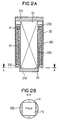
- the piezoelectric actuator 10 has a rectangular one Cross section on, with two opposite Long sides of the piezoelectric actuator 10 each have a contact pin 11 is arranged, which is conductive with the actuator Connection is established.
- the peripheral wall of the inner hollow form a closed Cross-section are in the embodiment 2A and 2B two opposing brackets 220 attached to the bottom plate 210 of the inner hollow mold 20, between which the piezoelectric actuator 10 with its two free long sides is inserted.
- the brackets 220 are preferably in the form of a segment of a circle in cross section molded and form with the piezoelectric Actuator 10 has a cylindrical design.
- the two brackets 220 are at their top end via a closed ring 230 connected to each other, which serves as a berth for the as Bourdon tube designed compression spring means 40 is used.
- a closed ring 230 connected to each other, which serves as a berth for the as Bourdon tube designed compression spring means 40 is used.
- the ring region 220 is provided with a spring bearing 41 into which one end of the compression spring means 40 is inserted.
- the outer hollow mold 30 with the base plate 310 and the peripheral wall 320 and the edge area 330 essentially corresponds the embodiment shown in Fig. 1, wherein the outer Hollow shape is preferably circular cylindrical.
- 2A and 2B is characterized by a particularly compact design, especially with regard to the actuator width so that the actuator unit with a minimal Required space e.g. when installed as an actuator for an injection valve gets along in a combustion chamber.
- FIG. 3 shows a further embodiment of the actuator unit, which is particularly narrow and e.g. can easily be inserted into a fuel injector.
- a single cup-shaped one Hollow mold 5, the piezoelectric actuator 100 and the pressure spring means 400 which is designed as a tubular spring.
- the hollow shape 5, the cross section of the cross section of the piezoelectric Actuator 100 is adapted, has on one end face a bottom plate 51 on which the piezoelectric Actuator 100 is present.
- This border area 53 is preferably annular, so that creates a circular opening in the middle.
- the compression spring means 400 On the inside surface of the edge region 53 is the compression spring means 400 with its one end supported, the edge region preferably with a spring bearing 410 is provided for securing the position.
- the Compression spring means 400 is at its other end against the supported piezoelectric actuator 100, being between piezoelectric Actuator and pressure spring means also a spring stop 420 is provided.
- the length of the hollow mold 5 is so designed that the pressure spring means 400 under pressure stands and the piezoelectric actuator 100 preferably with with a force of 800 N to 1000 N.
- the actuator When the piezoelectric actuator 100 has contact pins (not shown) is controlled, the actuator expands against the holding force of the pressure spring means 400 and moves the spring stop 420 in the direction of the edge region 53 of the Hollow shape 5.
- This longitudinal expansion of the piezoelectric actuator 100 can e.g. for placing an injection valve in a Internal combustion engine can be used by means of a Rod (not shown) by the one provided in the edge region 53 Opening and the compression spring means designed as a ring spring 410 to the spring stop 420 is sufficient, the expansion the actuator to open or close the valve becomes.
- the longitudinal expansion of the piezoelectric the actuator can also be transferred hydraulically.
- the actuator unit is designed that the piezoelectric actuator against by a pressure spring means its direction of expansion is prestressed under pressure.
- the Bourdon tube 400 is loaded under pressure so that a Reduction of material stress on the pretensioning device in particular the tubular spring 400 takes place and thus a long one Component life is guaranteed.
- the actuator is encapsulated in a pretensioner so that the bias on the piezoelectric actuator is preset can be, which simplifies transportation and assembly.
Landscapes
- Fuel-Injection Apparatus (AREA)
Applications Claiming Priority (2)
| Application Number | Priority Date | Filing Date | Title |
|---|---|---|---|
| DE19834424 | 1998-07-30 | ||
| DE19834424 | 1998-07-30 |
Publications (2)
| Publication Number | Publication Date |
|---|---|
| EP0977285A1 true EP0977285A1 (fr) | 2000-02-02 |
| EP0977285B1 EP0977285B1 (fr) | 2004-06-09 |
Family
ID=7875887
Family Applications (1)
| Application Number | Title | Priority Date | Filing Date |
|---|---|---|---|
| EP99114544A Expired - Lifetime EP0977285B1 (fr) | 1998-07-30 | 1999-07-23 | Charge de pression pour actuateur piezoélectrique |
Country Status (2)
| Country | Link |
|---|---|
| EP (1) | EP0977285B1 (fr) |
| DE (1) | DE59909675D1 (fr) |
Cited By (4)
| Publication number | Priority date | Publication date | Assignee | Title |
|---|---|---|---|---|
| US7145282B2 (en) | 2004-07-15 | 2006-12-05 | Delphi Technologies, Inc. | Actuator |
| WO2007107595A1 (fr) * | 2006-03-23 | 2007-09-27 | Siemens Aktiengesellschaft | Unité d'actionnement pour soupape d'injection haute pression |
| JP2009117834A (ja) * | 2007-11-08 | 2009-05-28 | Robert Bosch Gmbh | 保護層システムを備えたピエゾアクチエータ及びピエゾアクチエータモジュール |
| US7946669B2 (en) | 2004-08-19 | 2011-05-24 | Samsung Electronics Co., Ltd. | Aligning apparatus |
Citations (1)
| Publication number | Priority date | Publication date | Assignee | Title |
|---|---|---|---|---|
| US5004945A (en) * | 1988-09-26 | 1991-04-02 | Nippondenso Co., Ltd. | Piezoelectric type actuator |
-
1999
- 1999-07-23 EP EP99114544A patent/EP0977285B1/fr not_active Expired - Lifetime
- 1999-07-23 DE DE59909675T patent/DE59909675D1/de not_active Expired - Lifetime
Patent Citations (1)
| Publication number | Priority date | Publication date | Assignee | Title |
|---|---|---|---|---|
| US5004945A (en) * | 1988-09-26 | 1991-04-02 | Nippondenso Co., Ltd. | Piezoelectric type actuator |
Cited By (5)
| Publication number | Priority date | Publication date | Assignee | Title |
|---|---|---|---|---|
| US7145282B2 (en) | 2004-07-15 | 2006-12-05 | Delphi Technologies, Inc. | Actuator |
| US7946669B2 (en) | 2004-08-19 | 2011-05-24 | Samsung Electronics Co., Ltd. | Aligning apparatus |
| WO2007107595A1 (fr) * | 2006-03-23 | 2007-09-27 | Siemens Aktiengesellschaft | Unité d'actionnement pour soupape d'injection haute pression |
| JP2009117834A (ja) * | 2007-11-08 | 2009-05-28 | Robert Bosch Gmbh | 保護層システムを備えたピエゾアクチエータ及びピエゾアクチエータモジュール |
| EP2058873A3 (fr) * | 2007-11-08 | 2013-01-09 | Robert Bosch Gmbh | Piézoactionneur et module de piézoactionneur doté d'un système de couche de protection |
Also Published As
| Publication number | Publication date |
|---|---|
| EP0977285B1 (fr) | 2004-06-09 |
| DE59909675D1 (de) | 2004-07-15 |
Similar Documents
| Publication | Publication Date | Title |
|---|---|---|
| EP1292994B1 (fr) | Actionneur piezo-electrique | |
| EP1704323B1 (fr) | Actionneur piezoelectrique comportant des moyens pour compenser un changement de longueur thermique, et soupape d'injection de carburant comportant cet actionneur piezoelectrique | |
| EP2683961A1 (fr) | Coussinet pouvant être précontraint par refoulement de matériau et palier équipé de ce coussinet | |
| WO2003081023A1 (fr) | Soupape d'injection de carburant | |
| EP2440769B1 (fr) | Soupape d'injection avec un ensemble de transmission | |
| WO2006010182A1 (fr) | Raccord de conduites pour milieux sous haute pression | |
| DE10046323A1 (de) | Geschlossenes Hydrauliksystem | |
| EP1456527A1 (fr) | Dispositif pour translater une deviation d'un actionneur, notamment pour une soupape d'injection | |
| DE19948359A1 (de) | Aktoreinheit mit Keramikelement zur Temperaturkompensation | |
| EP0977285B1 (fr) | Charge de pression pour actuateur piezoélectrique | |
| DE19906467A1 (de) | Injektor mit einem Piezo-Mehrlagenaktor | |
| EP2440770A1 (fr) | Soupape d'injection dotée d'une unité de transmission | |
| EP1388360B1 (fr) | Elément filtrant annulaire pour filtre à fluides | |
| DE10321163B4 (de) | Verfahren zum Anbringen eines metallischen Dichtelements an einem Grundkörper eines Brennstoffeinspritzventils, sowie Brennstoffeinspritzventil | |
| DE10016247B4 (de) | Einspritzventil mit einer Dichtmembran | |
| DE202021105982U1 (de) | Druckbehälter | |
| DE10132756B4 (de) | Stellglied für Schaltelemente von Kraftstoff-Einspritzvorrichtungen | |
| DE102008030787A1 (de) | Zylinderkopfdichtung | |
| DE102005046178B3 (de) | Zylinderfeder | |
| EP1734253A1 (fr) | Soupape d'injection avec manchon et méthode de sa production | |
| DE102012218732B4 (de) | Verfahren zur Herstellung eines Einspritzventils | |
| EP1571366B1 (fr) | Support élastique | |
| DE102005029471B4 (de) | Verfahren zur Herstellung einer hohlzylindrischen Feder | |
| DE4141006A1 (de) | Dichtungsanordnung fuer einen kugelhahn | |
| DE102017203975A1 (de) | Anordnung einer Zylinderkopfhaube an einem Element einer Brennkraftmaschine |
Legal Events
| Date | Code | Title | Description |
|---|---|---|---|
| PUAI | Public reference made under article 153(3) epc to a published international application that has entered the european phase |
Free format text: ORIGINAL CODE: 0009012 |
|
| AK | Designated contracting states |
Kind code of ref document: A1 Designated state(s): DE FR IT |
|
| AX | Request for extension of the european patent |
Free format text: AL;LT;LV;MK;RO;SI |
|
| 17P | Request for examination filed |
Effective date: 20000801 |
|
| AKX | Designation fees paid |
Free format text: DE FR IT |
|
| 17Q | First examination report despatched |
Effective date: 20030908 |
|
| GRAP | Despatch of communication of intention to grant a patent |
Free format text: ORIGINAL CODE: EPIDOSNIGR1 |
|
| GRAS | Grant fee paid |
Free format text: ORIGINAL CODE: EPIDOSNIGR3 |
|
| GRAA | (expected) grant |
Free format text: ORIGINAL CODE: 0009210 |
|
| AK | Designated contracting states |
Kind code of ref document: B1 Designated state(s): DE FR IT |
|
| REF | Corresponds to: |
Ref document number: 59909675 Country of ref document: DE Date of ref document: 20040715 Kind code of ref document: P |
|
| RIN2 | Information on inventor provided after grant (corrected) |
Inventor name: LEWENTZ, GUENTER, DIPL.-ING. Inventor name: FRANK, WILHELM, DIPL.-ING. Inventor name: VOIGT, ANDREAS, DR.-ING. |
|
| ET | Fr: translation filed | ||
| PLBE | No opposition filed within time limit |
Free format text: ORIGINAL CODE: 0009261 |
|
| 26N | No opposition filed |
Effective date: 20050310 |
|
| REG | Reference to a national code |
Ref country code: FR Ref legal event code: TP |
|
| PLAA | Information modified related to event that no opposition was filed |
Free format text: ORIGINAL CODE: 0009299DELT |
|
| PLBE | No opposition filed within time limit |
Free format text: ORIGINAL CODE: 0009261 |
|
| STAA | Information on the status of an ep patent application or granted ep patent |
Free format text: STATUS: NO OPPOSITION FILED WITHIN TIME LIMIT |
|
| D26N | No opposition filed (deleted) | ||
| RIN2 | Information on inventor provided after grant (corrected) |
Inventor name: LEWENTZ, GUENTER, DIPL.-ING. Inventor name: FRANK, WILHELM, DIPL.-ING. Inventor name: VOIGT, ANDREAS, DR.-ING. |
|
| 26N | No opposition filed |
Effective date: 20050310 |
|
| REG | Reference to a national code |
Ref country code: DE Ref legal event code: R083 Ref document number: 59909675 Country of ref document: DE |
|
| PGFP | Annual fee paid to national office [announced via postgrant information from national office to epo] |
Ref country code: IT Payment date: 20140730 Year of fee payment: 16 |
|
| REG | Reference to a national code |
Ref country code: FR Ref legal event code: PLFP Year of fee payment: 17 |
|
| REG | Reference to a national code |
Ref country code: DE Ref legal event code: R084 Ref document number: 59909675 Country of ref document: DE |
|
| PGFP | Annual fee paid to national office [announced via postgrant information from national office to epo] |
Ref country code: FR Payment date: 20150626 Year of fee payment: 17 |
|
| PG25 | Lapsed in a contracting state [announced via postgrant information from national office to epo] |
Ref country code: IT Free format text: LAPSE BECAUSE OF NON-PAYMENT OF DUE FEES Effective date: 20150723 |
|
| PG25 | Lapsed in a contracting state [announced via postgrant information from national office to epo] |
Ref country code: FR Free format text: LAPSE BECAUSE OF NON-PAYMENT OF DUE FEES Effective date: 20160801 |
|
| REG | Reference to a national code |
Ref country code: FR Ref legal event code: ST Effective date: 20170331 |
|
| PGFP | Annual fee paid to national office [announced via postgrant information from national office to epo] |
Ref country code: DE Payment date: 20180731 Year of fee payment: 20 |
|
| REG | Reference to a national code |
Ref country code: DE Ref legal event code: R071 Ref document number: 59909675 Country of ref document: DE |