EP0977285A1 - Pressure loading for piezoelectric actuator - Google Patents
Pressure loading for piezoelectric actuator Download PDFInfo
- Publication number
- EP0977285A1 EP0977285A1 EP99114544A EP99114544A EP0977285A1 EP 0977285 A1 EP0977285 A1 EP 0977285A1 EP 99114544 A EP99114544 A EP 99114544A EP 99114544 A EP99114544 A EP 99114544A EP 0977285 A1 EP0977285 A1 EP 0977285A1
- Authority
- EP
- European Patent Office
- Prior art keywords
- actuator
- hollow
- piezoelectric actuator
- spring means
- piezoelectric
- Prior art date
- Legal status (The legal status is an assumption and is not a legal conclusion. Google has not performed a legal analysis and makes no representation as to the accuracy of the status listed.)
- Granted
Links
- 230000006835 compression Effects 0.000 claims description 15
- 238000007906 compression Methods 0.000 claims description 15
- 238000000576 coating method Methods 0.000 claims 1
- 238000010409 ironing Methods 0.000 claims 1
- 230000002093 peripheral effect Effects 0.000 description 14
- 238000002347 injection Methods 0.000 description 7
- 239000007924 injection Substances 0.000 description 7
- 239000000463 material Substances 0.000 description 7
- 238000002485 combustion reaction Methods 0.000 description 6
- 238000004519 manufacturing process Methods 0.000 description 4
- 238000012423 maintenance Methods 0.000 description 3
- 238000009434 installation Methods 0.000 description 2
- 229910000639 Spring steel Inorganic materials 0.000 description 1
- 230000007547 defect Effects 0.000 description 1
- 230000001419 dependent effect Effects 0.000 description 1
- 238000006073 displacement reaction Methods 0.000 description 1
- 230000000694 effects Effects 0.000 description 1
- 238000005538 encapsulation Methods 0.000 description 1
- 230000005284 excitation Effects 0.000 description 1
- 230000002349 favourable effect Effects 0.000 description 1
- 239000000446 fuel Substances 0.000 description 1
- 230000008719 thickening Effects 0.000 description 1
Images


Classifications
-
- H—ELECTRICITY
- H10—SEMICONDUCTOR DEVICES; ELECTRIC SOLID-STATE DEVICES NOT OTHERWISE PROVIDED FOR
- H10N—ELECTRIC SOLID-STATE DEVICES NOT OTHERWISE PROVIDED FOR
- H10N30/00—Piezoelectric or electrostrictive devices
- H10N30/80—Constructional details
- H10N30/88—Mounts; Supports; Enclosures; Casings
- H10N30/886—Additional mechanical prestressing means, e.g. springs
-
- H—ELECTRICITY
- H10—SEMICONDUCTOR DEVICES; ELECTRIC SOLID-STATE DEVICES NOT OTHERWISE PROVIDED FOR
- H10N—ELECTRIC SOLID-STATE DEVICES NOT OTHERWISE PROVIDED FOR
- H10N30/00—Piezoelectric or electrostrictive devices
- H10N30/50—Piezoelectric or electrostrictive devices having a stacked or multilayer structure
-
- F—MECHANICAL ENGINEERING; LIGHTING; HEATING; WEAPONS; BLASTING
- F02—COMBUSTION ENGINES; HOT-GAS OR COMBUSTION-PRODUCT ENGINE PLANTS
- F02M—SUPPLYING COMBUSTION ENGINES IN GENERAL WITH COMBUSTIBLE MIXTURES OR CONSTITUENTS THEREOF
- F02M2200/00—Details of fuel-injection apparatus, not otherwise provided for
- F02M2200/21—Fuel-injection apparatus with piezoelectric or magnetostrictive elements
Definitions
- the invention relates to an actuator unit with a prestressed piezoelectric actuator according to the preamble of Claim 1.
- Such actuator units are u.a. in vehicle technology for controlling injection valves of an internal combustion engine used.
- DE 38 44 134 C2 is an actuator known for an injection valve of an internal combustion engine, at a piezoelectric actuator is arranged in a Bourdon tube is and of this against the housing of the injection valve below Tension is biased.
- This structure of the actuator unit however, requires a lot of assembly and maintenance, because with every installation and removal the tensile load of the Bourdon tube with which the piezoelectric actuator is preloaded is to be reset.
- the tensile load on the Bourdon tube also leads to a very high material stress on the circumferential wall of the Bourdon tube, which is particularly amplified by the vibrations of the Bourdon tube which result from excitation of the piezoelectric actuator. If, for example, defects or damage to the wall material have occurred during the manufacture of the Bourdon tube wall, these can lead to cracks in the Bourdon tube, which greatly shorten the service life of the component. This applies in particular to the case in which the circumferential wall of the tube spring is provided with cutouts, as shown in DE 38 44 134, in order to make the tube spring sufficiently elastic to carry out the longitudinal expansion caused by the piezoelectric actuator.
- the object of the present invention is an actuator unit with a pre-stressed piezoelectric actuator To provide, in particular, for controlling an injection valve an internal combustion engine and is suitable a low installation and maintenance effort as well as a high one Excels lifespan.
- a piezoelectric actuator in an actuator unit from a biasing device encapsulated which a compression spring means in Form of a tube spring, which is the piezoelectric actuator loaded against its direction of expansion. Doing so the Bourdon tube is under pressure.
- the use of a pressure load Bourdon tube for preloading the piezoelectric actuator ensures a substantial reduction in material stress in the biasing device compared to one version subject to tensile stress, since none due to the compressive stress Cracks appear in the Bourdon tube.
- the Encapsulation of the piezoelectric actuator in the pretensioning device the transport, assembly and maintenance of the actuator unit it is particularly advantageous that the bias of the piezoelectric actuator during manufacture the unit is permanently determined.
- the pretensioning device two with their open ends pushed together cup-shaped hollow shapes, each shape and / or non-positive with one end of the piezoelectric Actuator are connected, the compression spring means between the two hollow molds is arranged under pressure.
- This Design allows one particularly in terms of its length compact structure of the actuator unit, with the exception of which sets a favorable and material-friendly pressure distribution.
- the piezoelectric actuator and the pressure spring means in a cup-shaped Hollow shape included, the ring-shaped trained pressure spring means against the piezoelectric actuator an inwardly projecting peripheral edge area supports the hollow form under pressure.
- This embodiment allows a particularly narrow design of the actuator unit and continues to be characterized by high fatigue strength and easy manufacture from.
- Fig. 1 shows a longitudinal section of a piezoelectric actuator 1, which consists of several stacked piezoelectric Individual elements can be constructed.
- the piezoelectric Actuator 1 is encapsulated in a pretensioner that from an inner cup-shaped hollow mold 2, an outer cup-shaped hollow mold 3 and one between the two hollow molds arranged compression spring means 4 exists.
- the inner one Hollow mold 2 has a base plate 21, which with one End face of the piezoelectric actuator 1 force and / or is positively connected.
- On the bottom plate 21 of the inner Hollow shape is followed by a peripheral wall 22 which almost the entire length of the piezoelectric actuator 1 extends and from an outwardly projecting circumferential Edge area 23 is completed.
- the outer hollow shape 3 also has a base plate 31 which is force and / or form-fitting with the other end face of the piezoelectric Actuator 1 is connected, the end face is centered on the base plate.
- a peripheral wall 32 is connected, the also essentially over the entire length of the Piezoelectric actuator 1 extends and the peripheral wall 22 of the inner hollow mold 2 to close to the bottom plate 21 thereof includes.
- the peripheral wall 32 of the outer hollow mold 3 is closed off by a peripheral widened edge region 33, the inward from the peripheral wall protrudes on the peripheral wall 22 of the inner hollow mold 2.
- the compression spring means 4 is between the projecting edge areas 23, 33 of the hollow molds 2, 3 arranged and is thereby in each case from the stop faces oriented towards the base plate the edge regions 23, 33 held, the Compression spring means 4 is under pressure to the inner and outer hollow mold 2, 3 the piezoelectric actuator with a force of preferably 800 N to 1000 N.
- the cup-shaped inner and outer hollow shapes 2, 3 are preferably cylindrical in cross-section with flat base plates 21, 22 and annular edge regions 23, 33.
- the hollow shapes can also be used as a rectangular tubular profile be formed, the cross section of the hollow molds preferably to the cross section of the piezoelectric Actuator is adjusted.
- a compression spring means 4 is preferred an annular, between the peripheral walls 22, 32 of the Hollow molds 2, 3 encircling Bourdon tube used.
- the cross sections the peripheral walls 22, 32 and the edge regions 23, 33, the inner and outer molds 2, 3 and the width of the pressure spring means 4 are designed so that between opposite Adequate clearance remains to land with possible deformations, e.g. due to temperature or other stress effects an increased friction between these Avoid areas.
- the opposite ones Surfaces of the hollow molds also coated with materials be characterized by a low coefficient of friction award.
- a special shape of the pressure spring e.g. through a thickening on the pressure spring means, for that to ensure that the two hollow forms even when occurring Do not rub deformations against each other.
- the base plates can and the sleeve-shaped peripheral walls with the flanged Edge areas through non-positive and / or positive connections be put together.
- one the hollow molds can be formed in one piece. Can continue the base plates of the hollow molds firmly with the end faces of the Piezoelectric actuator can be connected.
- the piezoelectric actuator 1 is connected via contact pins, which are not shown in Fig. 1 and preferably arranged in the base plate 31 of the outer hollow mold 3 Bushings protrude from the actuator unit, controlled, whereby a longitudinal expansion in the piezoelectric actuator is generated with the z.
- an injection valve be operated in an internal combustion engine can.
- the actuator unit is preferably installed in such a way that the longitudinal expansion of the piezoelectric actuator 1 the cup-shaped inner mold 2 against the pressure load of the Compression spring 4 moves.
- a pressure-loaded pressure spring 4 for biasing the piezoelectric actuator 1 against its longitudinal expansion becomes the material load on the two Hollow molds compared to a tensile stress on these hollow molds, as it is done in the prior art, significantly reduced.
- the encapsulated version of the pretensioner with two nested hollow molds that are under pressure are spaced apart from the compression spring means 4, in particular in terms of component length, a compact embodiment.
- the wall thicknesses of the peripheral walls the hollow shapes, especially when using spring steel, which is characterized by high material strength be chosen very small because the hollow shapes only the biasing forces of preferably 800 N to 1000 N on the need to transmit piezoelectric actuator and at the same time can be made very rigid. This enables one inexpensive manufacture.
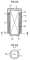
- the piezoelectric actuator 10 has a rectangular one Cross section on, with two opposite Long sides of the piezoelectric actuator 10 each have a contact pin 11 is arranged, which is conductive with the actuator Connection is established.
- the peripheral wall of the inner hollow form a closed Cross-section are in the embodiment 2A and 2B two opposing brackets 220 attached to the bottom plate 210 of the inner hollow mold 20, between which the piezoelectric actuator 10 with its two free long sides is inserted.
- the brackets 220 are preferably in the form of a segment of a circle in cross section molded and form with the piezoelectric Actuator 10 has a cylindrical design.
- the two brackets 220 are at their top end via a closed ring 230 connected to each other, which serves as a berth for the as Bourdon tube designed compression spring means 40 is used.
- a closed ring 230 connected to each other, which serves as a berth for the as Bourdon tube designed compression spring means 40 is used.
- the ring region 220 is provided with a spring bearing 41 into which one end of the compression spring means 40 is inserted.
- the outer hollow mold 30 with the base plate 310 and the peripheral wall 320 and the edge area 330 essentially corresponds the embodiment shown in Fig. 1, wherein the outer Hollow shape is preferably circular cylindrical.
- 2A and 2B is characterized by a particularly compact design, especially with regard to the actuator width so that the actuator unit with a minimal Required space e.g. when installed as an actuator for an injection valve gets along in a combustion chamber.
- FIG. 3 shows a further embodiment of the actuator unit, which is particularly narrow and e.g. can easily be inserted into a fuel injector.
- a single cup-shaped one Hollow mold 5, the piezoelectric actuator 100 and the pressure spring means 400 which is designed as a tubular spring.
- the hollow shape 5, the cross section of the cross section of the piezoelectric Actuator 100 is adapted, has on one end face a bottom plate 51 on which the piezoelectric Actuator 100 is present.
- This border area 53 is preferably annular, so that creates a circular opening in the middle.
- the compression spring means 400 On the inside surface of the edge region 53 is the compression spring means 400 with its one end supported, the edge region preferably with a spring bearing 410 is provided for securing the position.
- the Compression spring means 400 is at its other end against the supported piezoelectric actuator 100, being between piezoelectric Actuator and pressure spring means also a spring stop 420 is provided.
- the length of the hollow mold 5 is so designed that the pressure spring means 400 under pressure stands and the piezoelectric actuator 100 preferably with with a force of 800 N to 1000 N.
- the actuator When the piezoelectric actuator 100 has contact pins (not shown) is controlled, the actuator expands against the holding force of the pressure spring means 400 and moves the spring stop 420 in the direction of the edge region 53 of the Hollow shape 5.
- This longitudinal expansion of the piezoelectric actuator 100 can e.g. for placing an injection valve in a Internal combustion engine can be used by means of a Rod (not shown) by the one provided in the edge region 53 Opening and the compression spring means designed as a ring spring 410 to the spring stop 420 is sufficient, the expansion the actuator to open or close the valve becomes.
- the longitudinal expansion of the piezoelectric the actuator can also be transferred hydraulically.
- the actuator unit is designed that the piezoelectric actuator against by a pressure spring means its direction of expansion is prestressed under pressure.
- the Bourdon tube 400 is loaded under pressure so that a Reduction of material stress on the pretensioning device in particular the tubular spring 400 takes place and thus a long one Component life is guaranteed.
- the actuator is encapsulated in a pretensioner so that the bias on the piezoelectric actuator is preset can be, which simplifies transportation and assembly.
Landscapes
- Fuel-Injection Apparatus (AREA)
Abstract
Description
Die Erfindung betrifft eine Aktoreinheit mit einem vorgespannten piezoelektrischen Aktor gemäß dem Oberbegriff des Anspruchs 1.The invention relates to an actuator unit with a prestressed piezoelectric actuator according to the preamble of Claim 1.
Solche Aktoreinheiten werden u.a. in der Fahrzeugtechnik zum Steuern von Einspritzventilen einer Brennkraftmaschine eingesetzt. So ist aus der DE 38 44 134 C2 ein Stellantrieb für ein Einspritzventil einer Brennkraftmaschine bekannt, bei dem ein piezoelektrischer Aktor in einer Rohrfeder angeordnet ist und von dieser gegen das Gehäuse des Einspritzventils unter Zugbelastung vorgespannt wird. Dieser Aufbau der Aktoreinheit erfordert jedoch einen hohen Montage- und Wartungsaufwand, da bei jedem Ein- und Ausbau die Zugbelastung der Rohrfeder, mit der der piezoelektrische Aktor vorgespannt ist, neu eingestellt werden muß.Such actuator units are u.a. in vehicle technology for controlling injection valves of an internal combustion engine used. DE 38 44 134 C2 is an actuator known for an injection valve of an internal combustion engine, at a piezoelectric actuator is arranged in a Bourdon tube is and of this against the housing of the injection valve below Tension is biased. This structure of the actuator unit however, requires a lot of assembly and maintenance, because with every installation and removal the tensile load of the Bourdon tube with which the piezoelectric actuator is preloaded is to be reset.
Weiterhin führt die Zugbelastung auf die Rohrfeder auch
zu einer sehr hohen Materialbeanspruchung der Umfangswandung
der Rohrfeder, die insbesondere noch durch die Schwingungen
der Rohrfeder, die aus einer Erregung des piezoelektrischen
Aktors resultieren, verstärkt wird. Wenn bei der Herstellung
der Rohrfederwandung dann zum Beispiel Fehler oder Beschädigung
am Wandungsmaterial aufgetreten sind, können diese zu
Rissen in der Rohrfeder führen, die die Lebensdauer des Bauteils
stark verkürzen. Dies gilt insbesondere für den Fall,
daß die Umfangswandung der Rohrfeder mit Aussparungen, wie in
der DE 38 44 134 dargestellt, versehen ist, um die Rohrfeder
ausreichend elastisch zum Ausführen der vom piezoelektrischen
Aktor hervorgerufenen Längsdehnung zu machen. Bei der Fertigung
solcher Aussparungen in der Rohrfederwandung können
leicht feine Anrisse entstehen, die dann durch die Zugbelastung
der Rohrfeder anwachsen und damit zu einem Versagen des
Bauteils führen.
Verschiedene Formen von Rohrfedern zum Vorspannen des piezolektrischen
Aktors sind aus WO 99/08330 bekannt.
Aus DE 196 53 555 A1 ist ein piezoelektrischer Aktor bekannt,
der über eine Rohrfeder gegen seine Ausdehnungsrichtung auf
Druck belastet ist. Die Rohrfeder ist dabei auf Zug belastet.Furthermore, the tensile load on the Bourdon tube also leads to a very high material stress on the circumferential wall of the Bourdon tube, which is particularly amplified by the vibrations of the Bourdon tube which result from excitation of the piezoelectric actuator. If, for example, defects or damage to the wall material have occurred during the manufacture of the Bourdon tube wall, these can lead to cracks in the Bourdon tube, which greatly shorten the service life of the component. This applies in particular to the case in which the circumferential wall of the tube spring is provided with cutouts, as shown in DE 38 44 134, in order to make the tube spring sufficiently elastic to carry out the longitudinal expansion caused by the piezoelectric actuator. When producing such recesses in the Bourdon tube wall, fine cracks can easily occur, which then grow due to the tensile load on the Bourdon tube and thus lead to a failure of the component.
Various forms of tube springs for pretensioning the piezolectric actuator are known from WO 99/08330.
From DE 196 53 555 A1 a piezoelectric actuator is known which is loaded against its direction of expansion by means of a tubular spring against pressure. The Bourdon tube is loaded under tension.
Aufgabe der vorliegenden Erfindung ist es, eine Aktoreinheit mit einem vorgespannten piezoelektrischen Aktor bereitzustellen, die sich insbesondere zum Steuern eines Einspritzventils einer Brennkraftmaschine eignet und sich durch einen geringen Montage- und Wartungsaufwand sowie eine hohe Lebensdauer auszeichnet.The object of the present invention is an actuator unit with a pre-stressed piezoelectric actuator To provide, in particular, for controlling an injection valve an internal combustion engine and is suitable a low installation and maintenance effort as well as a high one Excels lifespan.
Diese Aufgabe wird bei einer Aktoreinheit durch die Merkmale des Anspruchs 1 gelöst. Gemäß der Erfindung wird ein piezoelektrischer Aktor in einer Aktoreinheit von einer Vorspanneinrichtung eingekapselt, die ein Druckfedermittel in Form einer Rohrfeder aufweist, das den piezoelektrischen Aktor gegen dessen Dehnungsrichtung druckbelastet. Dabei wird die Rohrfeder auf Druck belastet. Der Einsatz einer druckbelasteten Rohrfeder zum Vorspannen des piezoelektrischen Aktors sorgt für eine wesentliche Reduzierung der Materialbeanspruchung bei der Vorspanneinrichtung im Vergleich zu einer zugbelasteten Ausführung, da durch die Druckspannung keine Risse in der Rohrfeder entstehen. Weiterhin erleichtert die Verkapselung des piezoelektrischen Aktors in der Vorspanneinrichtung den Transport, die Montage sowie die Wartung der Aktoreinheit, wobei insbesondere vorteilhaft ist, daß die Vorspannung des piezoelektrischen Aktors bereits bei der Herstellung der Baueinheit auf Dauer festgelegt wird.With an actuator unit, this task is performed by Features of claim 1 solved. According to the invention, a piezoelectric actuator in an actuator unit from a biasing device encapsulated which a compression spring means in Form of a tube spring, which is the piezoelectric actuator loaded against its direction of expansion. Doing so the Bourdon tube is under pressure. The use of a pressure load Bourdon tube for preloading the piezoelectric actuator ensures a substantial reduction in material stress in the biasing device compared to one version subject to tensile stress, since none due to the compressive stress Cracks appear in the Bourdon tube. Furthermore, the Encapsulation of the piezoelectric actuator in the pretensioning device the transport, assembly and maintenance of the actuator unit, it is particularly advantageous that the bias of the piezoelectric actuator during manufacture the unit is permanently determined.
Gemäß einer bevorzugten Ausführungsform weist die Vorspanneinrichtung zwei mit ihren offenen Enden ineinander geschobene becherförmige Hohlformen auf, die jeweils form- und/oder kraftschlüssig mit einem Ende des piezoelektrischen Aktors verbunden sind, wobei das Druckfedermittel zwischen den beiden Hohlformen druckbelastet angeordnet ist. Diese Ausgestaltung ermöglicht einen in bezug auf seine Länge besonders kompakten Aufbau der Aktoreinheit, wobei sich außer dem eine günstige und materialschonende Druckverteilung einstellt.According to a preferred embodiment, the pretensioning device two with their open ends pushed together cup-shaped hollow shapes, each shape and / or non-positive with one end of the piezoelectric Actuator are connected, the compression spring means between the two hollow molds is arranged under pressure. This Design allows one particularly in terms of its length compact structure of the actuator unit, with the exception of which sets a favorable and material-friendly pressure distribution.
Gemäß einer weiteren bevorzugten Ausführungsform ist der piezoelektrische Aktor und das Drucktedermittel in einer becherförmigen Hohlform eingeschlossen, wobei das ringförmig ausgebildete Drucktedermittel den piezoelektrischen Aktor gegen einen nach innen vorspringenden umlaufenden Randbereich der Hohlform druckbelastet abstützt. Diese Ausführungsform läßt eine besonders schmale Ausgestaltung der Aktoreinheit zu und zeichnet sich weiterhin durch eine hohe Dauerfestigkeit und einfache Herstellung aus.According to a further preferred embodiment, the piezoelectric actuator and the pressure spring means in a cup-shaped Hollow shape included, the ring-shaped trained pressure spring means against the piezoelectric actuator an inwardly projecting peripheral edge area supports the hollow form under pressure. This embodiment allows a particularly narrow design of the actuator unit and continues to be characterized by high fatigue strength and easy manufacture from.
Weitere vorteilhafte Ausgestaltungen der Aktoreinheit sind in den abhängigen Ansprüchen offenbart.Further advantageous configurations of the actuator unit are disclosed in the dependent claims.
Die Erfindung wird anhand der Zeichnung näher erläutert.
Es zeigen:
Fig. 1 zeigt im Längsschnitt einen piezoelektrischen Aktor
1, der aus mehreren übereinandergestapelten piezoelektrischen
Einzelelementen aufgebaut sein kann. Der piezoelektrische
Aktor 1 ist in einer Vorspanneinrichtung verkapselt, die
aus einer inneren becherförmigen Hohlform 2, einer äußeren
becherförmigen Hohlform 3 und einem zwischen den beiden Hohlformen
angeordnetes Druckfedermittel 4 besteht. Die innere
Hohlform 2 weist eine Bodenplatte 21 auf, die mit der einen
Stirnfläche des piezoelektrischen Aktors 1 kraft- und/oder
formschlüssig verbunden ist. An die Bodenplatte 21 der inneren
Hohlform schließt sich eine Umfangswandung 22 an, die
sich nahezu über die gesamte Länge des piezoelektrischen Aktors
1 erstreckt und von einem nach außen vorspringenden umlaufenden
Randbereich 23 abgeschlossen ist. Die äußere Hohlform
3 weist ebenfalls eine Bodenplatte 31 auf, die kraft-und/oder
formschlüssig mit der anderen Stirnfläche des piezoelektrischen
Aktors 1 verbunden ist, wobei die Stirnfläche
mittig an der Bodenplatte anliegt. Mit der Bodenplatte 31 der
äußeren Hohlform 3 ist eine Umfangswandung 32 verbunden, die
sich ebenfalls im wesentlichen über die gesamte Länge des
piezoelektrischen Aktors 1 erstreckt und die Umfangswandung
22 der inneren Hohlform 2 bis nahe an deren Bodenplatte 21
mit umfaßt. Die Umfangswandung 32 der äußeren Hohlform 3 wird
von einem umlaufenden verbreiterten Randbereich 33 abgeschlossen,
der von der Umfangswandung nach innen in Richtung
auf die Umfangswandung 22 der inneren Hohlform 2 vorsteht.
Das Druckfedermittel 4 ist zwischen den vorspringenden Randbereichen
23, 33 der Hohlformen 2, 3 angeordnet und wird dabei
jeweils von den zur Bodenplatte hin orientierten Anschlagflächen
der Randbereiche 23, 33 gehalten, wobei das
Druckfedermittel 4 unter Druckbelastung steht, um über die
innere und äußere Hohlform 2, 3 den piezoelektrischen Aktor
mit einer Kraft von vorzugsweise 800 N bis 1000 N vorzuspannen.Fig. 1 shows a longitudinal section of a piezoelectric actuator
1, which consists of several stacked piezoelectric
Individual elements can be constructed. The piezoelectric
Actuator 1 is encapsulated in a pretensioner that
from an inner cup-shaped hollow mold 2, an outer
cup-shaped hollow mold 3 and one between the two hollow molds
arranged compression spring means 4 exists. The inner one
Hollow mold 2 has a
Die becherförmige innere und äußere Hohlform 2, 3 sind
im Querschnitt vorzugsweise zylinderförmig mit planen Bodenplatten
21, 22 und ringförmigen Randbereichen 23, 33 ausgebildet.
Die Hohlformen können jedoch auch als Rechteck-Rohrprofil
ausgeformt sein, wobei der Querschnitt der Hohlformen
vorzugsweise an den Querschnitt des piezoelektrischen
Aktors angepaßt ist. Als Druckfedermittel 4 wird vorzugsweise
eine ringförmig, zwischen den Umfangswandungen 22, 32 der
Hohlformen 2, 3 umlaufende Rohrfeder eingesetzt. Die Querschnitte
der Umfangswandungen 22, 32 und der Randbereiche 23,
33, der inneren und äußeren Hohlformen 2, 3 sowie die Breite
des Druckfedermittels 4 sind so ausgelegt, daß zwischen gegenüberliegenden
Flächen ein ausreichendes Spiel bleibt, um
bei möglichen Verformungen, z.B. aufgrund von Temperatur oder
anderen Belastungseffekten eine erhöhte Reibung zwischen diesen
Flächen zu vermeiden. Alternativ können die sich gegenüberliegenden
Flächen der Hohlformen auch mit Materialien beschichtet
werden, die sich durch einen niedrigen Reibungskoeffizienten
auszeichnen. Weiterhin besteht auch die Möglichkeit,
durch eine spezielle Formgebung des Druckfedermittels,
z.B. durch eine Verdickung am Druckfedermittel, dafür
zu sorgen, daß die beiden Hohlformen auch bei auftretenden
Verformungen nicht gegeneinander reiben.The cup-shaped inner and outer hollow shapes 2, 3 are
preferably cylindrical in cross-section with
Bei den beiden Hohlformen 2, 3 können die Bodenplatten und die hülsenförmigen Umfangswandungen mit den umgebördelten Randbereichen durch kraft- und/oder formschlüssige Steckverbindungen zusammengefügt werden. Alternativ kann auch eine der Hohlformen einstückig ausgebildet sein. Weiterhin können die Bodenplatten der Hohlformen fest mit den Stirnflächen des piezoelektrischen Aktors verbunden werden.With the two hollow molds 2, 3, the base plates can and the sleeve-shaped peripheral walls with the flanged Edge areas through non-positive and / or positive connections be put together. Alternatively, one the hollow molds can be formed in one piece. Can continue the base plates of the hollow molds firmly with the end faces of the Piezoelectric actuator can be connected.
Im Betrieb wird der piezoelektrische Aktor 1 über Kontaktstifte,
die in Fig. 1 nicht gezeigt sind und vorzugsweise
über in der Bodenplatte 31 der äußeren Hohlform 3 angeordnete
Durchführungen aus der Aktoreinheit herausstehen, angesteuert,
wobei durch Anlegen einer Spannung eine Längsdehnung im
piezoelektrischen Aktor erzeugt wird, mit der z. B. ein Einspritzventil
in einer Brennkraftmaschine betätigt werden
kann. Die Aktoreinheit ist dabei vorzugsweise so eingebaut,
daß die Längsdehnung des piezoelektrischen Aktors 1 die becherförmige
innere Hohlform 2 gegen die Druckbelastung des
Druckfedermittels 4 verschiebt.In operation, the piezoelectric actuator 1 is connected via contact pins,
which are not shown in Fig. 1 and preferably
arranged in the
Durch die Anordnung eines druckbelasteten Druckfedermittels
4 zum Vorspannen des piezoelektrischen Aktors 1 gegen
dessen Längsdehnung wird die Materialbelastung auf die beiden
Hohlformen im Vergleich zu einer Zugspannung auf diese Hohlformen,
wie sie im Stand der Technik erfolgt, wesentlich reduziert.
Die verkapselte Ausführung der Vorspanneinrichtung
mit zwei ineinander gesteckten Hohlformen, die druckbelastet
vom Druckfedermittel 4 beabstandet werden, ermöglicht insbesondere
in bezug auf die Bauteillänge eine kompakte Ausführungsform.
Weiterhin können die Wandstärken der Umfangswandungen
der Hohlformen insbesondere bei der Verwendung von Federstahl,
der sich durch eine hohe Materialfestigkeit auszeichnet,
sehr klein gewählt werden, da die Hohlformen nur
die Vorspannkräfte von vorzugsweise 800 N bis 1000 N auf den
piezoelektrischen Aktor übertragen müssen und gleichzeitig
sehr steif ausgebildet werden können. Dies ermöglicht eine
kostengünstige Herstellung.Due to the arrangement of a pressure-loaded
Bei der in Fig. 2A und 2B dargestellten weiteren Ausführungsform
weist der piezoelektrische Aktor 10 einen rechtekkigen
Querschnitt auf, wobei an zwei gegenüberliegenden
Längsseiten des piezoelektrischen Aktors 10 jeweils ein Kontaktstift
11 angeordnet ist, der mit dem Aktor leitend in
Verbindung steht. Im Gegensatz zur Ausführungsform gemäß Fig.
1, bei der die Umfangswandung der inneren Hohlform einen geschlossenen
Querschnitt aufweist, sind bei der Ausführungsform
gemäß Fig. 2A und 2B zwei sich gegenüberstehende Bügel
220 an der Bodenplatte 210 der inneren Hohlform 20 angebracht,
zwischen denen der piezoelektrische Aktor 10 mit seinen
beiden freien Längsseiten eingesetzt ist. Wie Fig. 2B
zeigt, sind die Bügel 220 im Querschnitt vorzugsweise kreissegmentförmig
ausgeformt und bilden mit dem piezoelektrischen
Aktor 10 eine zylindrische Bauform. Die beiden Bügel
220 sind an ihrem oberen Ende über einen geschlossenen Ring
230 miteinander verbunden, der als Anliegebereich für das als
Rohrfeder ausgebildete Druckfedermittel 40 dient. Um die Position
des Druckfedermittels 40 gegen Verschiebungen, z.B.
aufgrund von Belastungen der Aktoreinheit, zu sichern, ist
der Ringbereich 220 mit einem Federlager 41 versehen, in das
das eine Ende des Druckfedermittels 40 eingesetzt ist. Die
äußere Hohlform 30 mit der Bodenplatte 310 und der Umfangswandung
320 sowie dem Randbereich 330 entspricht im wesentlichen
der in Fig. 1 gezeigten Ausführungsform, wobei die äußere
Hohlform vorzugsweise kreiszylindrisch ausgebildet ist.
Die Ausführungsform gemäß Fig. 2A und 2B zeichnet sich durch
eine besonders kompakte Bauform, insbesondere in bezug auf
die Aktorbreite aus, so daß die Aktoreinheit mit einem minimalen
Raumbedarf z.B. beim Einbau als Stellglied für ein Einspritzventil
in einem Brennraum auskommt.In the further embodiment shown in FIGS. 2A and 2B
the
Fig. 3 zeigt eine weitere Ausführungsform der Aktoreinheit,
die besonders schmal ausgebildet ist und sich so z.B.
leicht in einem Schafft eines Einspritzventils einsetzen läßt.
Bei dieser Ausführungsform enthält eine einzelne becherförmige
Hohlform 5 den piezoelektrischen Aktor 100 und das Druckfedermittel
400 das als Rohrfeder ausgebildet ist. Die Hohlform
5, die mit ihrem Querschnitt an den Querschnitt des piezoelektrischen
Aktors 100 angepaßt ist, weist an einer Stirnseite
eine Bodenplatte 51 auf, an der der piezoelektrische
Aktor 100 anliegt. An die Bodenplatte 51 schließt sich eine
Umfangswandung 52 an, die von einem nach innen ragenden umlaufenden
Randbereich 53 abgeschlossen wird. Dieser Randbereich
53 ist vorzugsweise ringförmig ausgebildet, so daß sich
mittig eine kreisförmige Öffnung ergibt. An der Innenfläche
des Randbereiches 53 ist das Druckfedermittel 400 mit seinem
einen Ende abgestützt, wobei der Randbereich vorzugsweise mit
einem Federlager 410 zur Positionssicherung versehen ist. Das
Druckfedermittel 400 ist mit seinem anderen Ende gegen den
piezoelektrischen Aktor 100 abgestützt, wobei zwischen piezoelektrischen
Aktor und Druckfedermittel zusätzlich ein Federanschlag
420 vorgesehen ist. Die Länge der Hohlform 5 ist so
ausgelegt, daß das Druckfedermittel 400 unter Druckbelastung
steht und den piezoelektrischen Aktor 100 vorzugsweise mit
einer Kraft von 800 N bis 1000 N vorspannt.3 shows a further embodiment of the actuator unit,
which is particularly narrow and e.g.
can easily be inserted into a fuel injector.
In this embodiment, a single cup-shaped one
Wenn der piezoelektrische Aktor 100 über Kontaktstifte
(nicht gezeigt) angesteuert wird, so dehnt sich der Aktor gegen
die Haltekraft des Druckfedermittels 400 aus und bewegt
den Federanschlag 420 in Richtung auf den Randbereich 53 der
Hohlform 5. Diese Längsdehnung des piezoelektrischen Aktors
100 kann z.B. zum Stellen eines Einspritzventils in einer
Brennkraftmaschine eingesetzt werden, indem mittels einer
Stange (nicht gezeigt), die durch die im Randbereich 53 vorgesehene
Öffnung und das als Ringfeder ausgebildete Druckfedermittel
410 zum Federanschlag 420 reicht, die Ausdehnung
des Aktors zum Öffnen oder Schließen des Ventils genutzt
wird. Alternativ kann die Längsdehnung des piezoelektrischen
Aktors jedoch auch hydraulisch übertragen werden.When the
Gemäß der Erfindung ist die Aktoreinheit so ausgelegt,
daß der piezoelektrische Aktor durch ein Druckfedermittel gegen
seine Dehnungsrichtung druckbelastet vorgespannt ist. Dabei
wird die Rohrfeder 400 auf Druck belastet, so daß eine
Reduzierung der Materialbelastung auf die Vorspanneinrichtung
insbesondere die Rohrfeder 400 erfolgt und somit eine lange
Lebensdauer des Bauteils gewährleistet wird. Weiterhin ist
der Aktor in einer Vorspanneinrichtung eingekapselt, so daß
die Vorspannung auf dem piezoelektrischen Aktor fest voreingestellt
werden kann, wodurch sich Transport und Montage vereinfachen.According to the invention, the actuator unit is designed
that the piezoelectric actuator against by a pressure spring means
its direction of expansion is prestressed under pressure. Here
the
Claims (7)
wobei
die Vorspanneinrichtung den piezoelektrischen Aktor umfaßt und ein Drucktedermittel (4, 40; 400) aufweist, das den piezoelektrischen Aktor gegen seine Ausdehnungsrichtung druckbelastet, dadurch gekennzeichnet, daß das Druckfedermittel (4, 40, 400) als Rohrfeder ausgebildet ist, die auf Druck belastet ist.Actuator unit with a piezoelectric actuator (1; 10; 100) and an elastic pretensioning device (2, 3, 4; 20, 30, 40; 5, 400) that pretensions the piezoelectric actuator,
in which
the pretensioning device comprises the piezoelectric actuator and has a pressure spring means (4, 40; 400) which pressurizes the piezoelectric actuator against its direction of expansion, characterized in that the pressure spring means (4, 40, 400) is designed as a tubular spring which is loaded under pressure .
Applications Claiming Priority (2)
| Application Number | Priority Date | Filing Date | Title |
|---|---|---|---|
| DE19834424 | 1998-07-30 | ||
| DE19834424 | 1998-07-30 |
Publications (2)
| Publication Number | Publication Date |
|---|---|
| EP0977285A1 true EP0977285A1 (en) | 2000-02-02 |
| EP0977285B1 EP0977285B1 (en) | 2004-06-09 |
Family
ID=7875887
Family Applications (1)
| Application Number | Title | Priority Date | Filing Date |
|---|---|---|---|
| EP99114544A Expired - Lifetime EP0977285B1 (en) | 1998-07-30 | 1999-07-23 | Pressure loading for piezoelectric actuator |
Country Status (2)
| Country | Link |
|---|---|
| EP (1) | EP0977285B1 (en) |
| DE (1) | DE59909675D1 (en) |
Cited By (4)
| Publication number | Priority date | Publication date | Assignee | Title |
|---|---|---|---|---|
| US7145282B2 (en) | 2004-07-15 | 2006-12-05 | Delphi Technologies, Inc. | Actuator |
| WO2007107595A1 (en) * | 2006-03-23 | 2007-09-27 | Siemens Aktiengesellschaft | Actuator unit for a high-pressure injection valve |
| JP2009117834A (en) * | 2007-11-08 | 2009-05-28 | Robert Bosch Gmbh | Piezoactuator with protecting layer system, and piezoactuator module |
| US7946669B2 (en) | 2004-08-19 | 2011-05-24 | Samsung Electronics Co., Ltd. | Aligning apparatus |
Citations (1)
| Publication number | Priority date | Publication date | Assignee | Title |
|---|---|---|---|---|
| US5004945A (en) * | 1988-09-26 | 1991-04-02 | Nippondenso Co., Ltd. | Piezoelectric type actuator |
-
1999
- 1999-07-23 EP EP99114544A patent/EP0977285B1/en not_active Expired - Lifetime
- 1999-07-23 DE DE59909675T patent/DE59909675D1/en not_active Expired - Lifetime
Patent Citations (1)
| Publication number | Priority date | Publication date | Assignee | Title |
|---|---|---|---|---|
| US5004945A (en) * | 1988-09-26 | 1991-04-02 | Nippondenso Co., Ltd. | Piezoelectric type actuator |
Cited By (5)
| Publication number | Priority date | Publication date | Assignee | Title |
|---|---|---|---|---|
| US7145282B2 (en) | 2004-07-15 | 2006-12-05 | Delphi Technologies, Inc. | Actuator |
| US7946669B2 (en) | 2004-08-19 | 2011-05-24 | Samsung Electronics Co., Ltd. | Aligning apparatus |
| WO2007107595A1 (en) * | 2006-03-23 | 2007-09-27 | Siemens Aktiengesellschaft | Actuator unit for a high-pressure injection valve |
| JP2009117834A (en) * | 2007-11-08 | 2009-05-28 | Robert Bosch Gmbh | Piezoactuator with protecting layer system, and piezoactuator module |
| EP2058873A3 (en) * | 2007-11-08 | 2013-01-09 | Robert Bosch Gmbh | Piezo actuator and piezo actuator module with a protective coating system |
Also Published As
| Publication number | Publication date |
|---|---|
| EP0977285B1 (en) | 2004-06-09 |
| DE59909675D1 (en) | 2004-07-15 |
Similar Documents
| Publication | Publication Date | Title |
|---|---|---|
| EP1292994B1 (en) | Piezo actuator | |
| EP1704323B1 (en) | Piezo actuator comprising means for compensating thermal length modifications and fuel-injection valve comprising a piezo actuator | |
| EP2683961A1 (en) | Bushing which can be pretensioned by material displacement and bearing equipped with said bushing | |
| WO2003081023A1 (en) | Fuel injection valve | |
| EP2440769B1 (en) | Injection valve with a transmission assembly | |
| WO2006010182A1 (en) | Connection for high-pressure media conduits | |
| DE10046323A1 (en) | Closed hydraulic system | |
| EP1456527A1 (en) | Device for the translation of a displacement of an actuator, in particular for an injection valve | |
| DE19948359A1 (en) | Piezoelectric actuator unit e.g. for controlling motor vehicle combustion engine fuel injection valves | |
| EP0977285B1 (en) | Pressure loading for piezoelectric actuator | |
| DE19906467A1 (en) | Injector with piezo multilayer actuator in particular for common rail diesel injection system | |
| EP2440770A1 (en) | Injection valve comprising a transmission unit | |
| EP1388360B1 (en) | Ring filter insert for a fluid filter | |
| DE10321163B4 (en) | Method for attaching a metallic sealing element to a base body of a fuel injection valve, and fuel injection valve | |
| DE10016247B4 (en) | Injection valve with a sealing membrane | |
| DE202021105982U1 (en) | pressure vessel | |
| DE10132756B4 (en) | Actuator for switching elements of fuel injectors | |
| DE102008030787A1 (en) | Cylinder head gasket | |
| DE102005046178B3 (en) | Cylinder spring for piezoelectric-multilayer actuator, has middle pipe fastened between ends of inner and outer pipes, such that spring is formed with convolution in longitudinal section and closed against external gaseous or liquid media | |
| EP1734253A1 (en) | Injection valve with housing and method for producing said housing | |
| DE102012218732B4 (en) | Method for producing an injection valve | |
| EP1571366B1 (en) | Elastic support | |
| DE102005029471B4 (en) | Method for producing a hollow cylindrical spring | |
| DE4141006A1 (en) | Sealing assembly for ball valve with ball engageable secondary seal - which is in forced flow between two relatively movable piston elements with pressure faces. | |
| DE102017203975A1 (en) | Arrangement of a cylinder head cover on an element of an internal combustion engine |
Legal Events
| Date | Code | Title | Description |
|---|---|---|---|
| PUAI | Public reference made under article 153(3) epc to a published international application that has entered the european phase |
Free format text: ORIGINAL CODE: 0009012 |
|
| AK | Designated contracting states |
Kind code of ref document: A1 Designated state(s): DE FR IT |
|
| AX | Request for extension of the european patent |
Free format text: AL;LT;LV;MK;RO;SI |
|
| 17P | Request for examination filed |
Effective date: 20000801 |
|
| AKX | Designation fees paid |
Free format text: DE FR IT |
|
| 17Q | First examination report despatched |
Effective date: 20030908 |
|
| GRAP | Despatch of communication of intention to grant a patent |
Free format text: ORIGINAL CODE: EPIDOSNIGR1 |
|
| GRAS | Grant fee paid |
Free format text: ORIGINAL CODE: EPIDOSNIGR3 |
|
| GRAA | (expected) grant |
Free format text: ORIGINAL CODE: 0009210 |
|
| AK | Designated contracting states |
Kind code of ref document: B1 Designated state(s): DE FR IT |
|
| REF | Corresponds to: |
Ref document number: 59909675 Country of ref document: DE Date of ref document: 20040715 Kind code of ref document: P |
|
| RIN2 | Information on inventor provided after grant (corrected) |
Inventor name: LEWENTZ, GUENTER, DIPL.-ING. Inventor name: FRANK, WILHELM, DIPL.-ING. Inventor name: VOIGT, ANDREAS, DR.-ING. |
|
| ET | Fr: translation filed | ||
| PLBE | No opposition filed within time limit |
Free format text: ORIGINAL CODE: 0009261 |
|
| 26N | No opposition filed |
Effective date: 20050310 |
|
| REG | Reference to a national code |
Ref country code: FR Ref legal event code: TP |
|
| PLAA | Information modified related to event that no opposition was filed |
Free format text: ORIGINAL CODE: 0009299DELT |
|
| PLBE | No opposition filed within time limit |
Free format text: ORIGINAL CODE: 0009261 |
|
| STAA | Information on the status of an ep patent application or granted ep patent |
Free format text: STATUS: NO OPPOSITION FILED WITHIN TIME LIMIT |
|
| D26N | No opposition filed (deleted) | ||
| RIN2 | Information on inventor provided after grant (corrected) |
Inventor name: LEWENTZ, GUENTER, DIPL.-ING. Inventor name: FRANK, WILHELM, DIPL.-ING. Inventor name: VOIGT, ANDREAS, DR.-ING. |
|
| 26N | No opposition filed |
Effective date: 20050310 |
|
| REG | Reference to a national code |
Ref country code: DE Ref legal event code: R083 Ref document number: 59909675 Country of ref document: DE |
|
| PGFP | Annual fee paid to national office [announced via postgrant information from national office to epo] |
Ref country code: IT Payment date: 20140730 Year of fee payment: 16 |
|
| REG | Reference to a national code |
Ref country code: FR Ref legal event code: PLFP Year of fee payment: 17 |
|
| REG | Reference to a national code |
Ref country code: DE Ref legal event code: R084 Ref document number: 59909675 Country of ref document: DE |
|
| PGFP | Annual fee paid to national office [announced via postgrant information from national office to epo] |
Ref country code: FR Payment date: 20150626 Year of fee payment: 17 |
|
| PG25 | Lapsed in a contracting state [announced via postgrant information from national office to epo] |
Ref country code: IT Free format text: LAPSE BECAUSE OF NON-PAYMENT OF DUE FEES Effective date: 20150723 |
|
| PG25 | Lapsed in a contracting state [announced via postgrant information from national office to epo] |
Ref country code: FR Free format text: LAPSE BECAUSE OF NON-PAYMENT OF DUE FEES Effective date: 20160801 |
|
| REG | Reference to a national code |
Ref country code: FR Ref legal event code: ST Effective date: 20170331 |
|
| PGFP | Annual fee paid to national office [announced via postgrant information from national office to epo] |
Ref country code: DE Payment date: 20180731 Year of fee payment: 20 |
|
| REG | Reference to a national code |
Ref country code: DE Ref legal event code: R071 Ref document number: 59909675 Country of ref document: DE |