EP2440769B1 - Injection valve with a transmission assembly - Google Patents
Injection valve with a transmission assembly Download PDFInfo
- Publication number
- EP2440769B1 EP2440769B1 EP10721180.7A EP10721180A EP2440769B1 EP 2440769 B1 EP2440769 B1 EP 2440769B1 EP 10721180 A EP10721180 A EP 10721180A EP 2440769 B1 EP2440769 B1 EP 2440769B1
- Authority
- EP
- European Patent Office
- Prior art keywords
- pot
- piston
- injection valve
- nozzle needle
- chamber
- Prior art date
- Legal status (The legal status is an assumption and is not a legal conclusion. Google has not performed a legal analysis and makes no representation as to the accuracy of the status listed.)
- Not-in-force
Links
- 238000002347 injection Methods 0.000 title claims description 29
- 239000007924 injection Substances 0.000 title claims description 29
- 230000005540 biological transmission Effects 0.000 title claims description 17
- 238000007789 sealing Methods 0.000 claims description 23
- 239000000446 fuel Substances 0.000 claims description 17
- 238000002485 combustion reaction Methods 0.000 claims 1
- 230000007423 decrease Effects 0.000 description 2
- 230000002093 peripheral effect Effects 0.000 description 2
- 230000015572 biosynthetic process Effects 0.000 description 1
Images
Classifications
-
- F—MECHANICAL ENGINEERING; LIGHTING; HEATING; WEAPONS; BLASTING
- F02—COMBUSTION ENGINES; HOT-GAS OR COMBUSTION-PRODUCT ENGINE PLANTS
- F02M—SUPPLYING COMBUSTION ENGINES IN GENERAL WITH COMBUSTIBLE MIXTURES OR CONSTITUENTS THEREOF
- F02M51/00—Fuel-injection apparatus characterised by being operated electrically
- F02M51/06—Injectors peculiar thereto with means directly operating the valve needle
- F02M51/0603—Injectors peculiar thereto with means directly operating the valve needle using piezoelectric or magnetostrictive operating means
-
- F—MECHANICAL ENGINEERING; LIGHTING; HEATING; WEAPONS; BLASTING
- F02—COMBUSTION ENGINES; HOT-GAS OR COMBUSTION-PRODUCT ENGINE PLANTS
- F02M—SUPPLYING COMBUSTION ENGINES IN GENERAL WITH COMBUSTIBLE MIXTURES OR CONSTITUENTS THEREOF
- F02M47/00—Fuel-injection apparatus operated cyclically with fuel-injection valves actuated by fluid pressure
- F02M47/02—Fuel-injection apparatus operated cyclically with fuel-injection valves actuated by fluid pressure of accumulator-injector type, i.e. having fuel pressure of accumulator tending to open, and fuel pressure in other chamber tending to close, injection valves and having means for periodically releasing that closing pressure
- F02M47/027—Electrically actuated valves draining the chamber to release the closing pressure
-
- F—MECHANICAL ENGINEERING; LIGHTING; HEATING; WEAPONS; BLASTING
- F02—COMBUSTION ENGINES; HOT-GAS OR COMBUSTION-PRODUCT ENGINE PLANTS
- F02M—SUPPLYING COMBUSTION ENGINES IN GENERAL WITH COMBUSTIBLE MIXTURES OR CONSTITUENTS THEREOF
- F02M2200/00—Details of fuel-injection apparatus, not otherwise provided for
- F02M2200/70—Linkage between actuator and actuated element, e.g. between piezoelectric actuator and needle valve or pump plunger
- F02M2200/703—Linkage between actuator and actuated element, e.g. between piezoelectric actuator and needle valve or pump plunger hydraulic
- F02M2200/704—Linkage between actuator and actuated element, e.g. between piezoelectric actuator and needle valve or pump plunger hydraulic with actuator and actuated element moving in different directions, e.g. in opposite directions
Description
Die Erfindung betrifft ein Einspritzventil mit einer Übertragungseinheit gemäß Patentanspruch 1.The invention relates to an injection valve with a transmission unit according to claim 1.
Im Stand der Technik sind beispielsweise aus
In dem bekannten Stand der Technik wird die Auslenkung des Aktors in eine entsprechende Auslenkung der Düsennadel übertragen.In the known state of the art, the deflection of the actuator is transferred to a corresponding deflection of the nozzle needle.
Die Aufgabe der Erfindung besteht darin, eine verbesserte Übertragungseinheit für ein Einspritzventil bereitzustellen.The object of the invention is to provide an improved transmission unit for an injection valve.
Die Aufgabe der Erfindung wird durch das Einspritzventil gemäß Patentanspruch 1 gelöst. Das beschriebene Einspritzventil weist den Vorteil auf, dass die Übertragungseinheit einen verbesserten Aufbau aufweist.The object of the invention is achieved by the injection valve according to claim 1. The injection valve described has the advantage that the transmission unit has an improved structure.
Dazu weist die Übertragungseinheit zwei bewegliche Kolben auf, wobei zwischen den zwei Kolben ein beweglicher Topf angeordnet ist, wobei der bewegliche Topf in einem weiteren feststehenden Topf geführt ist, wobei der erste Kolben durch eine Öffnung des Bodens des weiteren Topfes mit einem dritten Dichtspalt geführt ist, wobei der zweite Kolben in einen hülsenförmigen Abschnitt des Topfes mit einem fünften Dichtspalt geführt ist, wobei zwischen dem weiteren Topf und dem Topf eine erste Kammer ausgebildet ist, wobei zwischen dem Topf und dem zweiten Kolben eine zweite Kammer ausgebildet ist, wobei die zwei Kammern über wenigstens einen Kanal miteinander verbunden sind und wobei ein Kolben mit der Düsennadel und der andere Kolben mit dem Aktor in Wirkverbindung steht. Mit Hilfe dieser Ausführungsform wird eine Übertragungseinheit bereitgestellt,
die zuverlässig eine Übertragung der Auslenkung des Aktors auf die Düsennadel ermöglicht.For this purpose, the transfer unit has two movable pistons, wherein a movable pot is arranged between the two pistons, wherein the movable pot is guided in a further fixed pot, wherein the first piston is guided through an opening in the bottom of the further pot with a third sealing gap wherein the second piston is guided in a sleeve-shaped portion of the pot with a fifth sealing gap, wherein between the further pot and the pot, a first chamber is formed, wherein between the pot and the second piston, a second chamber is formed, wherein the two chambers are connected to each other via at least one channel and wherein a piston with the nozzle needle and the other piston is in operative connection with the actuator. With the aid of this embodiment, a transmission unit is provided,
which reliably enables a transmission of the deflection of the actuator on the nozzle needle.
In einer Ausführungsform ist zwischen der Düsennadel und dem beweglichen Topf ein Federelement eingespannt, das den beweglichen Topf in Richtung auf den ersten Kolben vorspannt. Damit wird eine Vorspannung der Düsennadel in Richtung auf einen Dichtsitz ermöglicht.In one embodiment, a spring element is clamped between the nozzle needle and the movable pot, which biases the movable pot in the direction of the first piston. This allows a bias of the nozzle needle in the direction of a sealing seat.
In einer weiteren Ausführungsform liegt der erste Kolben auf einer Außenseite des Bodens des beweglichen Topfes auf. Damit wird ein Leerhub präzise eingestellt.In a further embodiment, the first piston rests on an outer side of the bottom of the movable pot. This will set an idle stroke precisely.
In einer weiteren Ausführungsform sind zwei Kanäle vorgesehen, die die zwei Kammern miteinander verbinden, wobei die zwei Kanäle in dem Boden des beweglichen Topfes eingebracht sind. Durch die Ausbildung von zwei Kanälen ist ein schneller Druckausgleich zwischen den zwei Kammern möglich.In a further embodiment, two channels are provided, which connect the two chambers with each other, wherein the two channels are inserted in the bottom of the movable pot. Due to the formation of two channels, a quick pressure equalization between the two chambers is possible.
In einer weiteren Ausführungsform begrenzt der zweite Kolben in einer zweiten Stirnfläche die zweite Kammer, wobei der weitere Topf mit einer zweiten Ringfläche, die den ersten Kolben umgibt, die erste Kammer begrenzt. Die zweite Stirnfläche des zweiten Kolbens ist dabei vorzugsweise kleiner ausgebildet als die zweite Ringfläche des weiteren Topfes. Auf diese Weise wird eine Übersetzung der Auslenkung des Aktors in eine größere Auslenkung der Düsennadel ermöglicht. Somit können kleine Auslenkungen, beispielsweise eines piezoelektrischen Aktors, in größere Auslenkungen der Düsennadel umgesetzt werden.In a further embodiment, the second piston limits the second chamber in a second end face, wherein the further pot with a second annular surface which surrounds the first piston delimits the first chamber. The second end face of the second piston is preferably formed smaller than the second annular surface of the other pot. In this way, a translation of the deflection of the actuator is made possible in a larger deflection of the nozzle needle. Thus, small deflections, such as a piezoelectric actuator, can be converted into larger deflections of the nozzle needle.
Die Erfindung wird im Folgenden anhand der Figuren näher erläutert. Es zeigen:
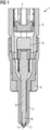
- Figur 1
- einen schematischen Aufbau eines Einspritzventils;
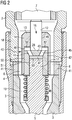
Figur 2- die Übertragungseinheit;
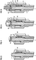
Figur 3- einen Düsenkörper mit Düsennadel;
Figur 4- eine Düsennadel mit zweitem Topf;
Figur 5- eine Düsennadel mit feststehendem Topf; und
Figur 6- eine Düsennadel mit Übertragungskolben.
- FIG. 1
- a schematic structure of an injection valve;
- FIG. 2
- the transmission unit;
- FIG. 3
- a nozzle body with nozzle needle;
- FIG. 4
- a nozzle needle with a second pot;
- FIG. 5
- a nozzle needle with a fixed pot; and
- FIG. 6
- a nozzle needle with transmission piston.
Der Aktor 7 kann beispielsweise als piezoelektrischer Aktor oder als magnetischer Aktor ausgebildet sein. Durch eine elektrische Bestromung des Aktors 7 verlängert sich der Aktor 7 und wirkt damit auf die Übertragungseinheit 40 ein. Die Übertragungseinheit 40 ist in der Weise ausgebildet, dass die Auslenkung des Aktors 7 auf die Düsennadel 5 übertragen wird. Vorzugsweise wird die Auslenkung des Aktors 7 in Richtung auf die Düsennadel 5 in eine entgegen gesetzte Bewegung der Düsennadel 5 in Richtung auf den Aktor 7 mit Hilfe der Übertragungseinheit 40 umgesetzt.The
Der erste Topf 14 begrenzt mit einer zweiten Ringfläche 52, die auf einer Innenseite des Bodens 13 ausgebildet ist, die erste Kammer 46. Das Endstück 17 begrenzt mit einer zweiten Stirnfläche 53 die zweite Kammer 47. Vorzugsweise ist die zweite Stirnfläche 53 kleiner als die zweite Ringfläche 52. Insbesondere ist die zweite Stirnfläche 53 halb so groß, wie die zweite Ringfläche. Das Flächenverhältnis zwischen der zweiten Stirnfläche 53 und der zweiten Ringfläche legt eine Übersetzung zwischen der Auslenkung des Aktors und der Auslenkung der Düsennadel fest. Zwischen dem zweiten Topf 42 und der Düsennadel 5 ist ein drittes Federelement 48 gespannt. Der erste und der zweite Kanal 44, 45 verbinden die erste und die zweite Kammer 46, 47. Der erste Kolben 12 ist über einen dritten Dichtspalt 49 im Boden 13 dichtend geführt.The
Der zweite Topf 42 ist über einen vierten Dichtspalt 50 in einem hülsenförmigen Abschnitt des feststehenden Topfes 14 dichtend geführt. Das Endstück 17 ist über einen fünften Dichtspalt 51 in dem hülsenförmigen Abschnitt des zweiten Topfes 42 dichtend geführt. Der dritte, vierte und fünfte Dichtspalt 49, 50, 51 können vorzugsweise eine Breite von 2 bis 20 µm, insbesondere im Bereich von 8 µm, aufweisen. Der dritte, vierte und fünfte Dichtspalt 49, 50, 51 sind in der Weise bemessen, dass die erste und zweite Kammer, die mit Kraftstoff gefüllt sind, gegenüber dem Innenraum des Einspritzventils bei einer kurzzeitigen Druckbeaufschlagung, die bei Einspritzvorgängen auftritt, abgedichtet sind. Der dritte, vierte und fünfte Dichtspalt 49, 50, 51 sorgen dafür, dass die erste und zweite Kammer 46, 47 immer mit Kraftstoff gefüllt ist und sich Druckunterschiede, die über längere Zeiträume, d.h. länger als Einspritzvorgänge vorhanden sind, ausgleichen.The
Die Übertragungseinheit 40 funktioniert wie folgt: im nicht angesteuerten Zustand des Aktors 7 sitzt die Düsennadel 5 mit der Dichtfläche 11 auf dem Dichtsitz 10 auf, so dass keine Verbindung zwischen dem Kraftstoffraum 8 und den Einspritzlöchern 9 vorliegt. Somit wird kein Kraftstoff eingespritzt. Dabei liegt der Aktor 7 an dem ersten Kolben 12 an. Der erste Kolben 12 liegt an dem zweiten Boden 43 des zweiten beweglichen Topfes 42 an und drückt somit über das dritte Federelement 48 die Düsennadel 5 in den Dichtsitz. Die erste und die zweite Kammer 46, 47 sind vollständig mit Kraftstoff gefüllt, wobei auch das Gehäuse 2 im Bereich der Übertragungseinheit 40 mit Kraftstoff gefüllt ist.The
Wird nun eine Einspritzung durchgeführt, so wird der Aktor 7 bestromt, so dass sich der Aktor nach unten in Richtung auf die Übertragungseinheit 40 bewegt. Dazu ist der Aktor 7 im oberen Bereich gegen das Gehäuse 2 des Einspritzventils abgestützt. Durch die Bewegung des Aktors 7 wird der erste Kolben 12 nach unten geschoben. Der erste Kolben 12 schiebt den zweiten Topf 42 nach unten. Damit wird der Druck in der zweiten Kammer 47 erhöht, so dass Kraftstoff aus der zweiten Kammer 47 über den ersten und den zweiten Kanal 44, 45 in die erste Kammer 46 strömt. Als Folge davon sinkt der Druck in der zweiten Kammer 47, so dass sich die Düsennadel 5 nach oben bewegt und vom Dichtsitz 10 abhebt. Folglich beginnt die Einspritzung.If an injection is now carried out, then the
Soll die Einspritzung beendet werden, so wird der Aktor 7 in der Weise angesteuert, dass er sich verkürzt. Als Folge davon sinkt die Kraft auf den ersten Kolben 12 und damit auch auf den zweiten Topf 42. Folglich sinkt der Druck in der zweiten Kammer 47. Zudem bewirkt das dritte Federelement 48, dass die Düsennadel 5 aus der zweiten Hülse 42 herausgezogen wird. Folglich fließt Kraftstoff von der ersten Kammer in die zweite Kammer zurück und die Düsennadel 5 wird nach unten auf den Dichtsitz gedrückt.If the injection is to be ended, the
Claims (6)
- Injection valve (1) for injecting fuel into an internal combustion engine, comprising an actuator (7), comprising a nozzle needle (5) which is assigned to a sealing seat (10), wherein a transmission unit (40) is provided which establishes an operative connection between the actuator (7) and the nozzle needle (5), characterized in that the transmission unit (40) has two movable pistons (12, 17), wherein a movable pot (42) is arranged between the two pistons (12, 17), wherein the movable pot (42) is guided via a fourth sealing gap (50) in a sleeve-shaped section of a further, fixed pot (14), wherein the first piston (12) is guided through an opening (15) in the bottom (13) of the further pot (14) with a third sealing gap (49), wherein the second piston (17) projects into a sleeve-shaped section of the pot (42) with a fifth sealing gap (51), wherein a first chamber (46) is formed between the further pot (42) and the pot (14), wherein a second chamber (47) is formed between the pot (42) and the second piston (17), wherein the two chambers (46, 47) are connected to one another via at least one duct (44, 45), wherein the sealing gaps (49, 50, 51) of the first and second chambers (46, 47) have a width of 2 to 20 µm, in particular a width of 8 µm, with the result that the first and second chambers (46, 47) are sealed with respect to an internal space of the injection valve for brief applications of pressure and equalize pressure differences over relatively long time periods, and wherein one piston (12, 17) is operatively connected to the nozzle needle (5), and the other piston (12, 17) is operatively connected to the actuator (7).
- Injection valve according to Claim 1, wherein a spring element (48), which prestresses the movable pot (42) in the direction of the first piston (12), is clamped in between the nozzle needle (5) and the movable pot (42).
- Injection valve according to one of Claims 1 and 2, wherein the first piston (12) rests on an upper side of a bottom (43) of the movable pot (42).
- Injection valve according to one of Claims 1 to 3, wherein two ducts (44, 45) are provided which connect the two chambers (46, 47), wherein the two ducts (44, 45) are formed in a bottom (43) of the movable pot (42).
- Injection valve according to one of Claims 1 to 4, wherein the second piston (17) bounds the second chamber (47) with a second end face (53), wherein the further pot (14) bounds the first chamber (46) with a second annular face (52) which surrounds the first piston (12), and wherein the second end face (53) is smaller than the second annular face (52).
- Injection valve according to one of Claims 1 to 5, wherein the fixed pot (14) is connected to the housing (2) via a disk-shaped edge region (41), wherein a drilled hole (6) is formed in the edge region (41), which drilled hole (6) connects an upper interior space of the injection valve to a lower interior space of the injection valve.
Applications Claiming Priority (2)
| Application Number | Priority Date | Filing Date | Title |
|---|---|---|---|
| DE102009024596A DE102009024596A1 (en) | 2009-06-10 | 2009-06-10 | Injection valve with transmission unit |
| PCT/EP2010/058158 WO2010142767A1 (en) | 2009-06-10 | 2010-06-10 | Injection valve comprising a transmission unit |
Publications (2)
| Publication Number | Publication Date |
|---|---|
| EP2440769A1 EP2440769A1 (en) | 2012-04-18 |
| EP2440769B1 true EP2440769B1 (en) | 2018-02-28 |
Family
ID=42301841
Family Applications (1)
| Application Number | Title | Priority Date | Filing Date |
|---|---|---|---|
| EP10721180.7A Not-in-force EP2440769B1 (en) | 2009-06-10 | 2010-06-10 | Injection valve with a transmission assembly |
Country Status (4)
| Country | Link |
|---|---|
| US (1) | US9222451B2 (en) |
| EP (1) | EP2440769B1 (en) |
| DE (1) | DE102009024596A1 (en) |
| WO (1) | WO2010142767A1 (en) |
Families Citing this family (7)
| Publication number | Priority date | Publication date | Assignee | Title |
|---|---|---|---|---|
| EP2674608B1 (en) * | 2012-06-13 | 2015-08-12 | Delphi International Operations Luxembourg S.à r.l. | Fuel injector |
| DE102012212266B4 (en) * | 2012-07-13 | 2015-01-22 | Continental Automotive Gmbh | fluid injector |
| DE102012212264B4 (en) | 2012-07-13 | 2014-02-13 | Continental Automotive Gmbh | Method for producing a solid state actuator |
| DE102014210101A1 (en) * | 2014-05-27 | 2015-12-03 | Robert Bosch Gmbh | fuel injector |
| DE102014226673A1 (en) * | 2014-12-19 | 2016-06-23 | Robert Bosch Gmbh | Hydraulic coupler unit for controlling a valve |
| DE102016109073B4 (en) * | 2015-06-05 | 2022-02-17 | Denso Corporation | Fuel injector and fuel injector controller |
| DE102015223043A1 (en) * | 2015-11-23 | 2017-05-24 | Robert Bosch Gmbh | Fuel injector |
Family Cites Families (35)
| Publication number | Priority date | Publication date | Assignee | Title |
|---|---|---|---|---|
| US5033442A (en) * | 1989-01-19 | 1991-07-23 | Cummins Engine Company, Inc. | Fuel injector with multiple variable timing |
| DE19918976A1 (en) | 1999-04-27 | 2000-11-02 | Bosch Gmbh Robert | Fuel injector and method for actuating it |
| US6575138B2 (en) | 1999-10-15 | 2003-06-10 | Westport Research Inc. | Directly actuated injection valve |
| US6298829B1 (en) | 1999-10-15 | 2001-10-09 | Westport Research Inc. | Directly actuated injection valve |
| DE19950760A1 (en) * | 1999-10-21 | 2001-04-26 | Bosch Gmbh Robert | Fuel injection valve esp. for fuel injection systems of IC engines with piezo-electric or magneto-strictive actuator and valve closing body operable by valve needle working with valve |
| GB9925753D0 (en) * | 1999-10-29 | 1999-12-29 | Lucas Industries Ltd | Fuel injector |
| JP2002202022A (en) * | 2000-10-30 | 2002-07-19 | Denso Corp | Valve driving device and fuel injection valve |
| FR2819021B1 (en) * | 2000-12-28 | 2005-03-04 | Denso Corp | HYDRAULIC CONTROL VALVE AND FUEL INJECTOR USING SUCH A VALVE |
| DE10250720A1 (en) | 2002-10-31 | 2004-05-13 | Robert Bosch Gmbh | Injector |
| DE10250917B3 (en) | 2002-10-31 | 2004-06-03 | Siemens Ag | Method for operating an injection valve with a piezoelectric actuator and control device |
| DE10326914A1 (en) * | 2003-06-16 | 2005-01-05 | Robert Bosch Gmbh | Controlling internal combustion engine fuel injection valve involves controlling valve for closing movement during further injection so valve needle adopts stroke position different from null position |
| DE10333696A1 (en) * | 2003-07-24 | 2005-02-24 | Robert Bosch Gmbh | Fuel injector |
| DE10333695A1 (en) | 2003-07-24 | 2005-03-03 | Robert Bosch Gmbh | Fuel injector |
| DE10353045A1 (en) * | 2003-11-13 | 2005-06-23 | Siemens Ag | Fuel injection valve |
| DE102004002299A1 (en) | 2004-01-16 | 2005-08-04 | Robert Bosch Gmbh | Fuel injector with directly controlled injection valve member |
| DE102004005456A1 (en) * | 2004-02-04 | 2005-08-25 | Robert Bosch Gmbh | Fuel injector with direct-acting injection valve member |
| DE102004028522A1 (en) * | 2004-06-11 | 2005-12-29 | Robert Bosch Gmbh | Fuel injector with variable Aktorhubübersetzung |
| DE102004035313A1 (en) * | 2004-07-21 | 2006-02-16 | Robert Bosch Gmbh | Fuel injector with two-stage translator |
| ITTO20040512A1 (en) | 2004-07-23 | 2004-10-23 | Magneti Marelli Powertrain Spa | FUEL INJECTOR PROVIDED WITH HIGH FLEXIBILITY NEEDLE |
| DE102004062006A1 (en) * | 2004-12-23 | 2006-07-13 | Robert Bosch Gmbh | Fuel injector with directly controlled injection valve member |
| DE102005004738A1 (en) | 2005-02-02 | 2006-08-10 | Robert Bosch Gmbh | Fuel injector with direct needle control for an internal combustion engine |
| DE102005015731A1 (en) | 2005-04-06 | 2006-10-12 | Robert Bosch Gmbh | Fuel injector with piezo actuator |
| DE102005025953A1 (en) * | 2005-06-06 | 2006-12-07 | Siemens Ag | Compensator e.g. for injection valve, has pot shaped body with pot base and recess with piston provided at axially extending guide of piston having clearance fit of recess |
| DE102005036444A1 (en) * | 2005-08-03 | 2007-02-08 | Robert Bosch Gmbh | injection |
| DE102005042786B4 (en) | 2005-09-08 | 2009-04-16 | Siemens Ag | Fuel injector with hermetically sealed hydraulic system |
| DE102006027327B4 (en) | 2006-06-13 | 2018-08-02 | Robert Bosch Gmbh | Fuel injector with direct needle control |
| DE102006031567A1 (en) * | 2006-07-07 | 2008-01-10 | Siemens Ag | Injection system and method for manufacturing an injection system |
| DE102007003216A1 (en) | 2007-01-22 | 2008-07-24 | Robert Bosch Gmbh | Injector for fuel injection system of internal combustion engine in motor vehicle, has actuator piston with two actuator piston surfaces that are hydraulically coupled with respective needle piston surfaces of needle piston |
| JP4270294B2 (en) * | 2007-03-05 | 2009-05-27 | 株式会社デンソー | Fuel injection valve |
| JP4270293B2 (en) * | 2007-03-05 | 2009-05-27 | 株式会社デンソー | Fuel injection valve |
| JP4270292B2 (en) * | 2007-03-05 | 2009-05-27 | 株式会社デンソー | Fuel injection valve |
| JP4333757B2 (en) * | 2007-03-13 | 2009-09-16 | 株式会社デンソー | Fuel injection valve |
| JP4386928B2 (en) | 2007-04-04 | 2009-12-16 | 株式会社デンソー | Injector |
| DE102007023384A1 (en) * | 2007-05-18 | 2008-11-20 | Robert Bosch Gmbh | Injector for a fuel injection system |
| JP4491474B2 (en) * | 2007-05-31 | 2010-06-30 | 日立オートモティブシステムズ株式会社 | Fuel injection valve and its stroke adjusting method |
-
2009
- 2009-06-10 DE DE102009024596A patent/DE102009024596A1/en not_active Ceased
-
2010
- 2010-06-10 WO PCT/EP2010/058158 patent/WO2010142767A1/en active Application Filing
- 2010-06-10 US US13/377,240 patent/US9222451B2/en not_active Expired - Fee Related
- 2010-06-10 EP EP10721180.7A patent/EP2440769B1/en not_active Not-in-force
Also Published As
| Publication number | Publication date |
|---|---|
| US20120160214A1 (en) | 2012-06-28 |
| WO2010142767A1 (en) | 2010-12-16 |
| US9222451B2 (en) | 2015-12-29 |
| DE102009024596A1 (en) | 2011-04-07 |
| EP2440769A1 (en) | 2012-04-18 |
Similar Documents
| Publication | Publication Date | Title |
|---|---|---|
| EP2440769B1 (en) | Injection valve with a transmission assembly | |
| EP1989436B1 (en) | Fuel injection device for an internal combustion engine | |
| WO2006067015A1 (en) | Injector for a fuel-injection system in an internal combustion engine | |
| EP1307651B1 (en) | Metering valve with a hydraulic transmission element | |
| DE10320592A1 (en) | Feed pump, in particular high-pressure fuel pump for an internal combustion engine | |
| DE10333696A1 (en) | Fuel injector | |
| EP3822475B1 (en) | Valve for metering a fluid | |
| EP2440770B1 (en) | Injection valve with transmission unit | |
| EP2310662B1 (en) | Fuel injector | |
| EP1872008B1 (en) | Fuel-injector with two-stage opening | |
| DE10217594A1 (en) | Fuel injection valve for IC engines has throttle gap formed by Laser/erosion drilling, and positioned separate from guide gaps, for cheaper fabrication of gaps | |
| DE19940300A1 (en) | Control valve for an injector | |
| EP1664525B1 (en) | Metering device | |
| DE102009026564A1 (en) | Fuel injector for injecting fuel into combustion chamber of internal-combustion engine, has control valve element that is formed and arranged such that small resulting hydraulic force is applied on control valve element | |
| EP1961953A1 (en) | Multiway valve | |
| DE102014226003A1 (en) | Fuel injector | |
| DE102004042190A1 (en) | Fuel injector with two separately controlled by a servo valve control chambers | |
| DE10050599B4 (en) | Injection valve with a pump piston | |
| DE19946842C2 (en) | high pressure pump | |
| DE102005029471B4 (en) | Method for producing a hollow cylindrical spring | |
| DE102006036782B4 (en) | injector | |
| WO2007054828A2 (en) | Injection valve featuring improved cooling | |
| EP1256708A2 (en) | Fuel injection device for an internal-combustion engine | |
| DE102005025138B4 (en) | metering valve | |
| DE102014225999A1 (en) | Fuel injector |
Legal Events
| Date | Code | Title | Description |
|---|---|---|---|
| PUAI | Public reference made under article 153(3) epc to a published international application that has entered the european phase |
Free format text: ORIGINAL CODE: 0009012 |
|
| 17P | Request for examination filed |
Effective date: 20120110 |
|
| AK | Designated contracting states |
Kind code of ref document: A1 Designated state(s): AL AT BE BG CH CY CZ DE DK EE ES FI FR GB GR HR HU IE IS IT LI LT LU LV MC MK MT NL NO PL PT RO SE SI SK SM TR |
|
| DAX | Request for extension of the european patent (deleted) | ||
| 17Q | First examination report despatched |
Effective date: 20161031 |
|
| REG | Reference to a national code |
Ref country code: DE Ref legal event code: R079 Ref document number: 502010014704 Country of ref document: DE Free format text: PREVIOUS MAIN CLASS: F02M0051060000 Ipc: F02M0047020000 |
|
| RIC1 | Information provided on ipc code assigned before grant |
Ipc: F02M 51/06 20060101ALI20170712BHEP Ipc: F02M 47/02 20060101AFI20170712BHEP |
|
| GRAP | Despatch of communication of intention to grant a patent |
Free format text: ORIGINAL CODE: EPIDOSNIGR1 |
|
| INTG | Intention to grant announced |
Effective date: 20170918 |
|
| GRAS | Grant fee paid |
Free format text: ORIGINAL CODE: EPIDOSNIGR3 |
|
| GRAA | (expected) grant |
Free format text: ORIGINAL CODE: 0009210 |
|
| AK | Designated contracting states |
Kind code of ref document: B1 Designated state(s): AL AT BE BG CH CY CZ DE DK EE ES FI FR GB GR HR HU IE IS IT LI LT LU LV MC MK MT NL NO PL PT RO SE SI SK SM TR |
|
| REG | Reference to a national code |
Ref country code: GB Ref legal event code: FG4D Free format text: NOT ENGLISH Ref country code: CH Ref legal event code: EP |
|
| REG | Reference to a national code |
Ref country code: AT Ref legal event code: REF Ref document number: 974430 Country of ref document: AT Kind code of ref document: T Effective date: 20180315 |
|
| REG | Reference to a national code |
Ref country code: IE Ref legal event code: FG4D Free format text: LANGUAGE OF EP DOCUMENT: GERMAN |
|
| REG | Reference to a national code |
Ref country code: DE Ref legal event code: R096 Ref document number: 502010014704 Country of ref document: DE |
|
| REG | Reference to a national code |
Ref country code: FR Ref legal event code: PLFP Year of fee payment: 9 |
|
| REG | Reference to a national code |
Ref country code: NL Ref legal event code: MP Effective date: 20180228 |
|
| REG | Reference to a national code |
Ref country code: LT Ref legal event code: MG4D |
|
| PG25 | Lapsed in a contracting state [announced via postgrant information from national office to epo] |
Ref country code: FI Free format text: LAPSE BECAUSE OF FAILURE TO SUBMIT A TRANSLATION OF THE DESCRIPTION OR TO PAY THE FEE WITHIN THE PRESCRIBED TIME-LIMIT Effective date: 20180228 Ref country code: NO Free format text: LAPSE BECAUSE OF FAILURE TO SUBMIT A TRANSLATION OF THE DESCRIPTION OR TO PAY THE FEE WITHIN THE PRESCRIBED TIME-LIMIT Effective date: 20180528 Ref country code: LT Free format text: LAPSE BECAUSE OF FAILURE TO SUBMIT A TRANSLATION OF THE DESCRIPTION OR TO PAY THE FEE WITHIN THE PRESCRIBED TIME-LIMIT Effective date: 20180228 Ref country code: HR Free format text: LAPSE BECAUSE OF FAILURE TO SUBMIT A TRANSLATION OF THE DESCRIPTION OR TO PAY THE FEE WITHIN THE PRESCRIBED TIME-LIMIT Effective date: 20180228 Ref country code: ES Free format text: LAPSE BECAUSE OF FAILURE TO SUBMIT A TRANSLATION OF THE DESCRIPTION OR TO PAY THE FEE WITHIN THE PRESCRIBED TIME-LIMIT Effective date: 20180228 Ref country code: NL Free format text: LAPSE BECAUSE OF FAILURE TO SUBMIT A TRANSLATION OF THE DESCRIPTION OR TO PAY THE FEE WITHIN THE PRESCRIBED TIME-LIMIT Effective date: 20180228 Ref country code: CY Free format text: LAPSE BECAUSE OF FAILURE TO SUBMIT A TRANSLATION OF THE DESCRIPTION OR TO PAY THE FEE WITHIN THE PRESCRIBED TIME-LIMIT Effective date: 20180228 |
|
| PGFP | Annual fee paid to national office [announced via postgrant information from national office to epo] |
Ref country code: DE Payment date: 20180630 Year of fee payment: 9 |
|
| PG25 | Lapsed in a contracting state [announced via postgrant information from national office to epo] |
Ref country code: BG Free format text: LAPSE BECAUSE OF FAILURE TO SUBMIT A TRANSLATION OF THE DESCRIPTION OR TO PAY THE FEE WITHIN THE PRESCRIBED TIME-LIMIT Effective date: 20180528 Ref country code: SE Free format text: LAPSE BECAUSE OF FAILURE TO SUBMIT A TRANSLATION OF THE DESCRIPTION OR TO PAY THE FEE WITHIN THE PRESCRIBED TIME-LIMIT Effective date: 20180228 Ref country code: LV Free format text: LAPSE BECAUSE OF FAILURE TO SUBMIT A TRANSLATION OF THE DESCRIPTION OR TO PAY THE FEE WITHIN THE PRESCRIBED TIME-LIMIT Effective date: 20180228 Ref country code: GR Free format text: LAPSE BECAUSE OF FAILURE TO SUBMIT A TRANSLATION OF THE DESCRIPTION OR TO PAY THE FEE WITHIN THE PRESCRIBED TIME-LIMIT Effective date: 20180529 |
|
| PGFP | Annual fee paid to national office [announced via postgrant information from national office to epo] |
Ref country code: FR Payment date: 20180620 Year of fee payment: 9 |
|
| PG25 | Lapsed in a contracting state [announced via postgrant information from national office to epo] |
Ref country code: MT Free format text: LAPSE BECAUSE OF FAILURE TO SUBMIT A TRANSLATION OF THE DESCRIPTION OR TO PAY THE FEE WITHIN THE PRESCRIBED TIME-LIMIT Effective date: 20180228 |
|
| PG25 | Lapsed in a contracting state [announced via postgrant information from national office to epo] |
Ref country code: EE Free format text: LAPSE BECAUSE OF FAILURE TO SUBMIT A TRANSLATION OF THE DESCRIPTION OR TO PAY THE FEE WITHIN THE PRESCRIBED TIME-LIMIT Effective date: 20180228 Ref country code: AL Free format text: LAPSE BECAUSE OF FAILURE TO SUBMIT A TRANSLATION OF THE DESCRIPTION OR TO PAY THE FEE WITHIN THE PRESCRIBED TIME-LIMIT Effective date: 20180228 Ref country code: RO Free format text: LAPSE BECAUSE OF FAILURE TO SUBMIT A TRANSLATION OF THE DESCRIPTION OR TO PAY THE FEE WITHIN THE PRESCRIBED TIME-LIMIT Effective date: 20180228 Ref country code: IT Free format text: LAPSE BECAUSE OF FAILURE TO SUBMIT A TRANSLATION OF THE DESCRIPTION OR TO PAY THE FEE WITHIN THE PRESCRIBED TIME-LIMIT Effective date: 20180228 Ref country code: PL Free format text: LAPSE BECAUSE OF FAILURE TO SUBMIT A TRANSLATION OF THE DESCRIPTION OR TO PAY THE FEE WITHIN THE PRESCRIBED TIME-LIMIT Effective date: 20180228 |
|
| REG | Reference to a national code |
Ref country code: DE Ref legal event code: R097 Ref document number: 502010014704 Country of ref document: DE |
|
| PG25 | Lapsed in a contracting state [announced via postgrant information from national office to epo] |
Ref country code: CZ Free format text: LAPSE BECAUSE OF FAILURE TO SUBMIT A TRANSLATION OF THE DESCRIPTION OR TO PAY THE FEE WITHIN THE PRESCRIBED TIME-LIMIT Effective date: 20180228 Ref country code: SK Free format text: LAPSE BECAUSE OF FAILURE TO SUBMIT A TRANSLATION OF THE DESCRIPTION OR TO PAY THE FEE WITHIN THE PRESCRIBED TIME-LIMIT Effective date: 20180228 Ref country code: SM Free format text: LAPSE BECAUSE OF FAILURE TO SUBMIT A TRANSLATION OF THE DESCRIPTION OR TO PAY THE FEE WITHIN THE PRESCRIBED TIME-LIMIT Effective date: 20180228 Ref country code: DK Free format text: LAPSE BECAUSE OF FAILURE TO SUBMIT A TRANSLATION OF THE DESCRIPTION OR TO PAY THE FEE WITHIN THE PRESCRIBED TIME-LIMIT Effective date: 20180228 |
|
| PLBE | No opposition filed within time limit |
Free format text: ORIGINAL CODE: 0009261 |
|
| STAA | Information on the status of an ep patent application or granted ep patent |
Free format text: STATUS: NO OPPOSITION FILED WITHIN TIME LIMIT |
|
| REG | Reference to a national code |
Ref country code: CH Ref legal event code: PL |
|
| 26N | No opposition filed |
Effective date: 20181129 |
|
| GBPC | Gb: european patent ceased through non-payment of renewal fee |
Effective date: 20180610 |
|
| PG25 | Lapsed in a contracting state [announced via postgrant information from national office to epo] |
Ref country code: SI Free format text: LAPSE BECAUSE OF FAILURE TO SUBMIT A TRANSLATION OF THE DESCRIPTION OR TO PAY THE FEE WITHIN THE PRESCRIBED TIME-LIMIT Effective date: 20180228 |
|
| REG | Reference to a national code |
Ref country code: BE Ref legal event code: MM Effective date: 20180630 |
|
| REG | Reference to a national code |
Ref country code: IE Ref legal event code: MM4A |
|
| PG25 | Lapsed in a contracting state [announced via postgrant information from national office to epo] |
Ref country code: LU Free format text: LAPSE BECAUSE OF NON-PAYMENT OF DUE FEES Effective date: 20180610 Ref country code: MC Free format text: LAPSE BECAUSE OF FAILURE TO SUBMIT A TRANSLATION OF THE DESCRIPTION OR TO PAY THE FEE WITHIN THE PRESCRIBED TIME-LIMIT Effective date: 20180228 |
|
| PG25 | Lapsed in a contracting state [announced via postgrant information from national office to epo] |
Ref country code: GB Free format text: LAPSE BECAUSE OF NON-PAYMENT OF DUE FEES Effective date: 20180610 Ref country code: IE Free format text: LAPSE BECAUSE OF NON-PAYMENT OF DUE FEES Effective date: 20180610 Ref country code: LI Free format text: LAPSE BECAUSE OF NON-PAYMENT OF DUE FEES Effective date: 20180630 Ref country code: CH Free format text: LAPSE BECAUSE OF NON-PAYMENT OF DUE FEES Effective date: 20180630 |
|
| PG25 | Lapsed in a contracting state [announced via postgrant information from national office to epo] |
Ref country code: BE Free format text: LAPSE BECAUSE OF NON-PAYMENT OF DUE FEES Effective date: 20180630 |
|
| REG | Reference to a national code |
Ref country code: AT Ref legal event code: MM01 Ref document number: 974430 Country of ref document: AT Kind code of ref document: T Effective date: 20180610 |
|
| PG25 | Lapsed in a contracting state [announced via postgrant information from national office to epo] |
Ref country code: AT Free format text: LAPSE BECAUSE OF NON-PAYMENT OF DUE FEES Effective date: 20180610 |
|
| REG | Reference to a national code |
Ref country code: DE Ref legal event code: R119 Ref document number: 502010014704 Country of ref document: DE |
|
| PG25 | Lapsed in a contracting state [announced via postgrant information from national office to epo] |
Ref country code: TR Free format text: LAPSE BECAUSE OF FAILURE TO SUBMIT A TRANSLATION OF THE DESCRIPTION OR TO PAY THE FEE WITHIN THE PRESCRIBED TIME-LIMIT Effective date: 20180228 |
|
| PG25 | Lapsed in a contracting state [announced via postgrant information from national office to epo] |
Ref country code: DE Free format text: LAPSE BECAUSE OF NON-PAYMENT OF DUE FEES Effective date: 20200101 |
|
| PG25 | Lapsed in a contracting state [announced via postgrant information from national office to epo] |
Ref country code: HU Free format text: LAPSE BECAUSE OF FAILURE TO SUBMIT A TRANSLATION OF THE DESCRIPTION OR TO PAY THE FEE WITHIN THE PRESCRIBED TIME-LIMIT; INVALID AB INITIO Effective date: 20100610 Ref country code: PT Free format text: LAPSE BECAUSE OF FAILURE TO SUBMIT A TRANSLATION OF THE DESCRIPTION OR TO PAY THE FEE WITHIN THE PRESCRIBED TIME-LIMIT Effective date: 20180228 |
|
| REG | Reference to a national code |
Ref country code: DE Ref legal event code: R081 Ref document number: 502010014704 Country of ref document: DE Owner name: VITESCO TECHNOLOGIES GMBH, DE Free format text: FORMER OWNER: CONTINENTAL AUTOMOTIVE GMBH, 30165 HANNOVER, DE |
|
| PG25 | Lapsed in a contracting state [announced via postgrant information from national office to epo] |
Ref country code: FR Free format text: LAPSE BECAUSE OF NON-PAYMENT OF DUE FEES Effective date: 20190630 Ref country code: MK Free format text: LAPSE BECAUSE OF NON-PAYMENT OF DUE FEES Effective date: 20180228 |
|
| PG25 | Lapsed in a contracting state [announced via postgrant information from national office to epo] |
Ref country code: IS Free format text: LAPSE BECAUSE OF FAILURE TO SUBMIT A TRANSLATION OF THE DESCRIPTION OR TO PAY THE FEE WITHIN THE PRESCRIBED TIME-LIMIT Effective date: 20180628 |